| Project Proposal | Project Planning | Project Documentation | Final Project Presenation |
|---|
Design consideration
I want the circuit to be cheap , simple and easy to fabricate. I plan to run this as a workshop and cost is a factor for me. My target audience are students with little electronics background. I will not use smt components as the students are from different disciplines and do not have soldering background. I have considered using IR transmitter and receiver. It will be done in version 2. I must source for the correct laser that is not too high powered. Eventually I only found a red 5mW laser that is suitable. A warning sign will be placed near to the game to remind player not to shine the laser gun on thier own or others eyes .
Initial Experiment with ATTiny 85
I tried with Attiny 85, the servo movement was jerky when I tried to control to specific degree of movement. I tried different servo libraries and was not successful. I gave up the idea and decided to fabricate an ATmega328 instead.Process - 3d Print
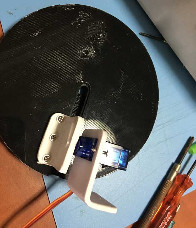
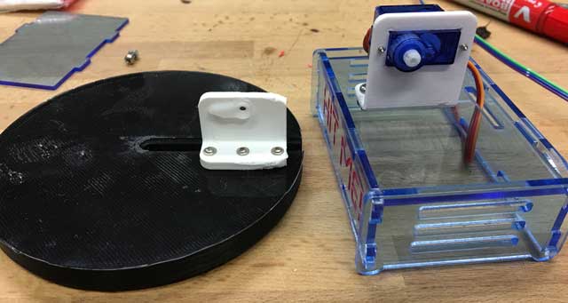
I start by designing my target first . I used Inventor to design it.
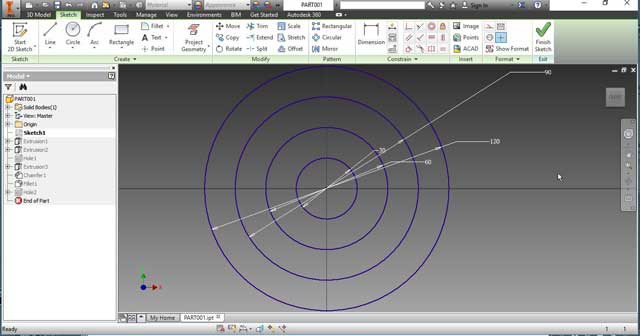
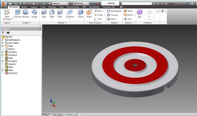
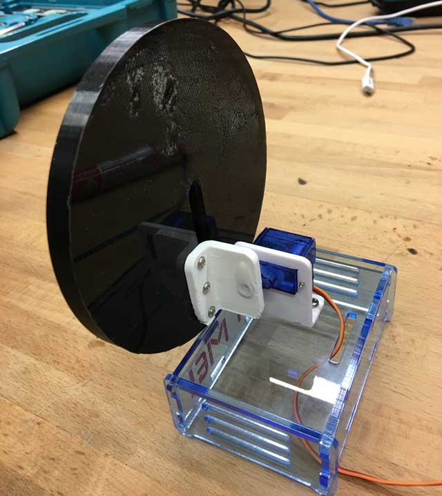
I designed my bracket. I decided to 3d print it because I need something that is light. I am using a very small servo motor. If the bracket is too heavy, the servo motor might not be able to turn.
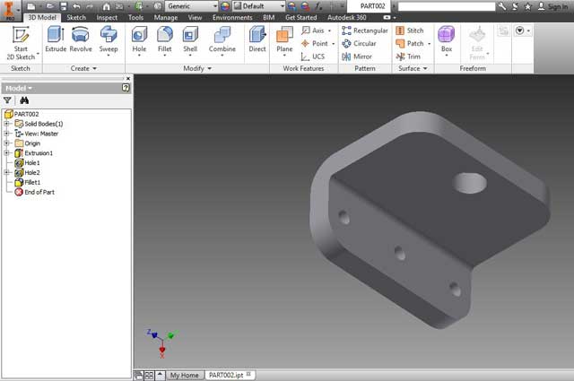
and mount for servo motor using inventor. This will prevent the servo from moving when the target falls.
Download the target
Download the servo mount
Download bracket
There are some problems with the 3d print. some parts of first layer wasn't sticking to the platform. Since this is just the back, I decide to continue with this prototype. I have printed a white target as the final one.
The deadline is 22 June
According to my schedule, I have completed the following tasks :-
1. 29 May - test circuit using Arduino
2. 30 May - Design the target board with Inventor
3. 31 May - Design microcontroller board
I do not have much time. The remaining tasks are:-
1. Fabricate pcb, laser cut and 3d print
2. Trouble shoot , testing and document.
In order to complete the remaining task, I have to be excused from my work and concentrate full time during office hours.
What has worked?
Everything so far seems to be fine as I am according to schedule.
The circuited tested ok using an Arduino Uno.
The target design looks ok
The microcontroller design is done.
What hasn't work?
So far, all is working.
What questions need to be resolved?
1. Whether the servo can withstand the weight of the target?
2. Whether our milling machine will be able to mill my pcb since the atmega328 has very close pins and we are using v bit instead of mill bit?
What have you learned?
I have learned to follow the schedule as close as possible so that I can deliver the project on time. I have applied what I have learned in this fab academy journey and put them into practice, integrating them into a final project.
Process - Laser cut
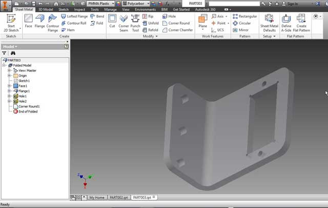
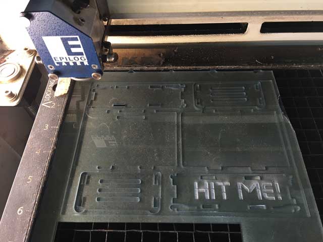
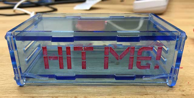
The chasis needs to be transparent so that students are able to see what is inside. I want the chasis to be easy asembled and disasembled as students might want want to see the pcb connections. I love the clip design. The chasis is a raspberry pi chasis done by Phillip Burgess Adafruit. The project was available free some years back but it seems that they have changed their policy. The design is done using Corel draw. Ventilations are added to the sides .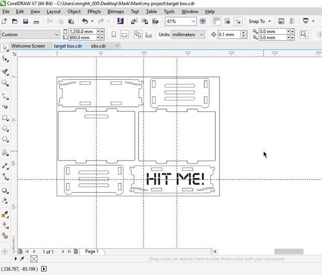
Download the box cdr files here.
Some tricks
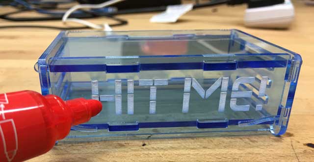
I assembled the chasis and wanted the box to look more interesting. So I used a red marker to colour the engraved words.
Putting the target box together
The electronics - Make an arduino clone board
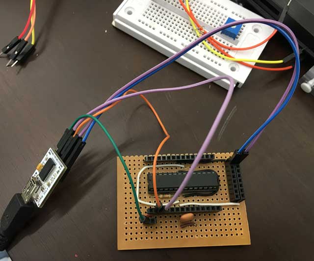
I need to create a board that is flexible so that I can add on other functions to it. i have decided to make an arduino board. I used Eagle to design my pcb. I am using an ATmega328 processor. The crystal is running at 16Mhz. I have created more VCC and ground pins so that I can easily add more devices in the future.
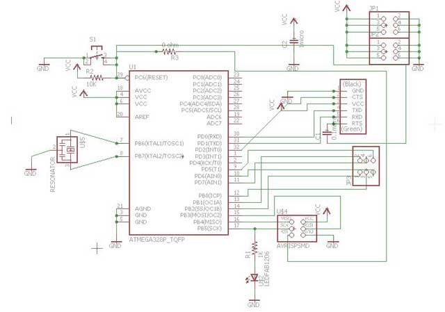
The board layout
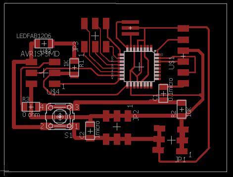
The pcb
Download the atmega328.sch
Download the atmega328.brd
How to burn bootloader
Credits goes to Dan Chen. His steps are very clear.1. Download additional boards by placing the url
2. Install the board
3. Slect the appropriate chip and internal / external crystal speed and burn bootloader.
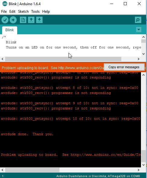
To program the chip , use FTDI.Oh No...it is not working!
I fabricated 2 boards but none of them work. I first soldered all the components on one of the boards. It did not worked. thinking that it was due to my soldering, I soldered another board with the bare minimum components. I spent 2 days troubleshooting and discoved that I forgot to connect the reset pin! I used a small jumper cable to rectify the proplem. One was able to upload the bootloader whereas the other one with the minimum components cannot. When I tried to program both, programer is not responding. I cannot find the problems. It might be due to my soldering. I have problems seeing and soldering such a tiny chip.
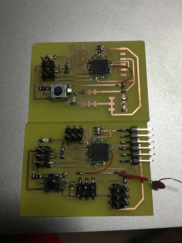
As time is running out, I shall try using a veroboard and use a normal IC chip rather than the smt chip. Everything seems to be fine now. I am able to burn the bootloader and upload my program.
The result
Back to trouble shooting
I begin to trouble shoot. I tested all connectivity and they seems ok. However, when I measured to resonator, one of the leg is shorted to ground. I immediately replaced it and voila....It worked again. I am able to burn the bootloader and upload the blink program! Thank God!
Finally managed to get the board up
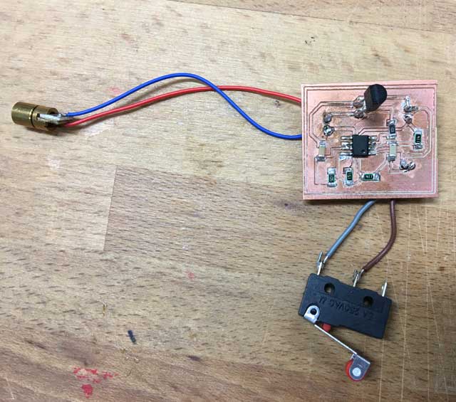
The target circuit
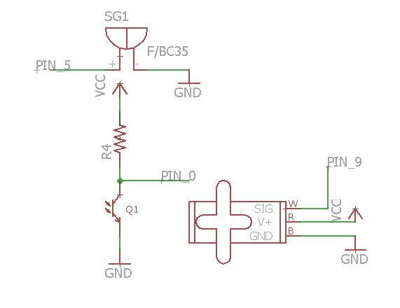
When the laser shines on the phototransistor, the servo will fall to 10 degrees, LED turn on and the buzzer will sound, the target move back to 90 degrees. turn off LED and buzzer.
The Program
#includeServo myservo;
int ledPinRed = 13; // LED on digital pin 13
int inPin = 7 ; // the input pin for the IR phototransistor
int buzzer = 5; // the output pin for the buzzer
void setup() {
pinMode(inPin, INPUT); // declare IR phototransistor as input
pinMode(buzzer, OUTPUT); // declare the buzzer as output
myservo.attach(9);
myservo.write(90);
}
void loop(){
while(digitalRead(inPin) != LOW) {}; // read input value
myservo.write(10);
digitalWrite(ledPinRed, HIGH);
digitalWrite(buzzer, HIGH); //Make some sound
delay(800);
digitalWrite(buzzer, LOW);
myservo.write(90);
digitalWrite(ledPinRed, LOW);
}
The gun
The gun was modified from the m8 rubberband gun. By modifying the design, it became a 2 in one gun. You can either use rubberband or the laser gun. A laser and electronic board was added to it. I have added a 9V battery that can be easily changed by sliding the battery out. Attached is the corel draw file for laser cutting. For assembly, you can refer to the original pdf by the author.
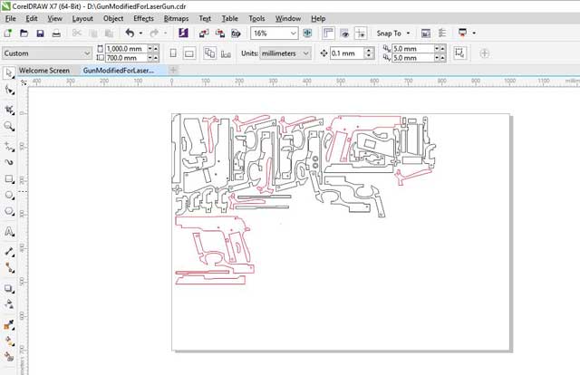
You can download the cdr file here.
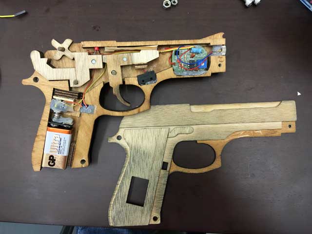
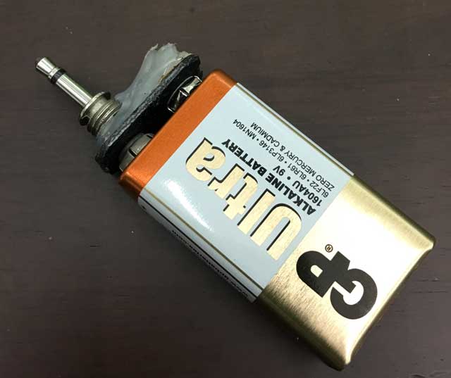
I have decided to use a mono jack as the battery adapter so that I easily slide out the battery.
The on off switch is added to save battery
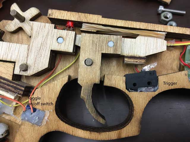
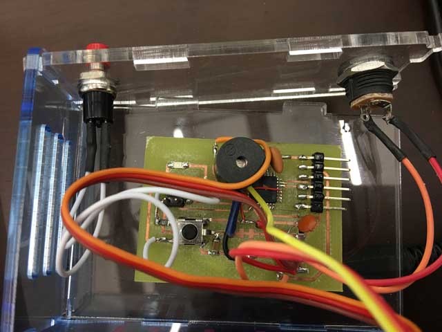
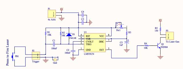
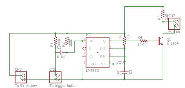
In order to add some difficulty, the circuit will time out even if the trigger is held close. The deisgn is using a 555 timer as a one shot monostable oscillator. The original circuit is designed by my colleague, Mr Peh King Sing, for another project. he has graciously allowed me to use his circuit .
The original design
I re-designed the circuit
Board layout
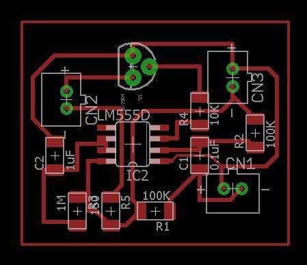
Download laser.brd
Download laser.sch
The laser gun is designed using a 555 timer that acts as a one shot timer. The output is hign for 1 second after the switch is closed. This is to add some difficulty to the game so that even though the player held on to the switch, the circuit will time out. The on time is calculated based on Time = 1.1 x 1M(R3) x 1U(C2)
Besides adding difficulty, it will also help in case someone accidentally point the laser at somebody's eyes. The laser will not shine continuously. So the 555timer also acts as a safety feature too.
What I have learned?
Limitations
The circuit depends on the ambience light of the environment. If the place is too bright, there might be false trigger. One of the way is to add a variable resistor to the reciver and tune the circuit every time before playing. The better way is to use IR frequency instead. This will be done in the later stage.
My thoughts
It was a tough journey for me juggling between study and work. Every week, if I can complete my assignments, it is an achievement to me. This course has taught me from saying Impossible to I'm possible! We had good relationships between students and everyone is willing to share their knowledge. We learnt a lot from each other.
As Neil put it, this is just the begining to our journey into digital fabrication. There are still a lot of things that I do not know. I hope to apply what I have learnt and share and contribute back so that our students will benefit from it.