This week our assignment is to use the board we designed the week before last week to do something.
I used Arduino as a tool to do this.
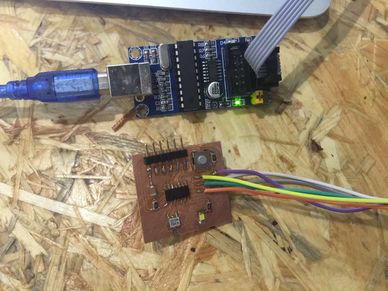
First, connect the board with USBtinyISP. USBtinyISP works as a programmer.
And now open Arduino IDE and of the settings.
|| Add new boards manager
As default, your Arduino IDE cannot recognize boards outside of the Arduino family. To introduce more boards to Arduino IDE, we need to add need boards manager as following:
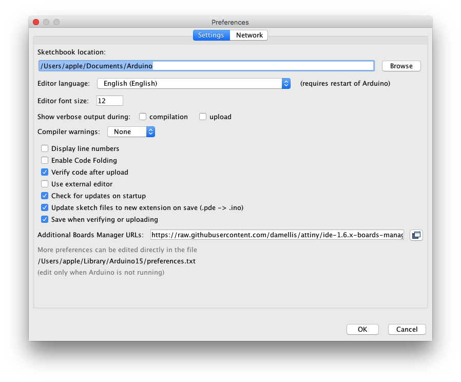
Above I added a website address of attiny chips in the path as Arduino - > Preferences
https://raw.githubusercontent.com/damellis/attiny/ide-1.6.x-boards-manager/package_damellis_attiny_index.json
Click OK to enable it.
|| Tool
Now you can move to Tool menu and find the correct settings for your chip. For the board I made and the programmer I used. The settings are:
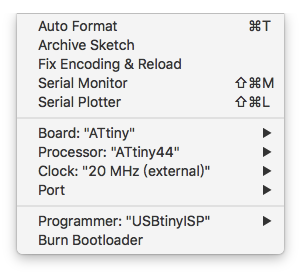
After these settings, click Bootloader to upload the firmware to the new board to get it ready for codes in Arduino IDE.
|| Program!
After successfully upload the boot loader, programming time is on!
I added one button and one led to the original design. To control it, I need to understand which pin it is connected to, and what will happen when those pins set HIGH or LOW. Following is the scheme of the circuit:
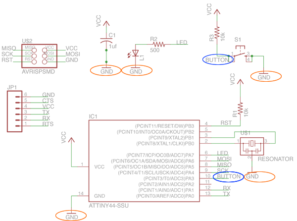
So LED is connected to digital pin 7, and button is connected to digital pin 3. When pin 7 is HIGH, LED will light up. When button pressed, digital pin 3 will get a LOW signal. Following is the sketch I wrote:
          /*
          This is a testing sketch for my embeded programming assignment.

          Lit Liao
          May 2th, 2016
         */

        // the setup function runs once when you press reset or power the board
        void setup() {
          // initialize digital pin 7 as an output, pin 3 as input.
          pinMode(7, OUTPUT);
          pinMode(3, INPUT);
        }

        // the loop function runs over and over again forever
        void loop() {
          if(digitalRead(3) == LOW)
          {
            digitalWrite(7, HIGH);   // turn the LED on (HIGH is the voltage level)
          }
          else{
            digitalWrite(7,LOW);
          }
          delay(100);              // wait for 100ms
        }
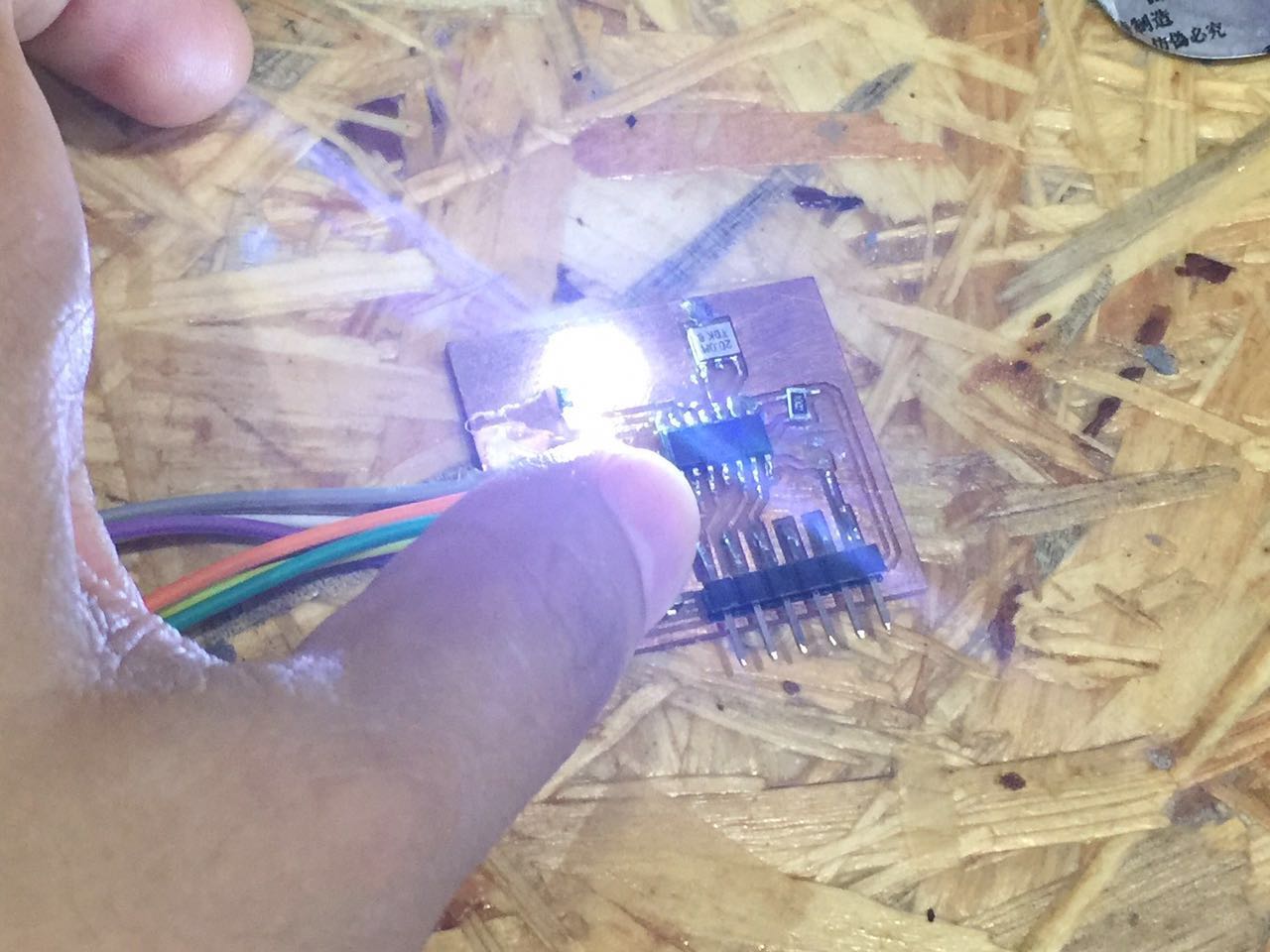
After uploading this sketch to my board, I got a button controlled LED: