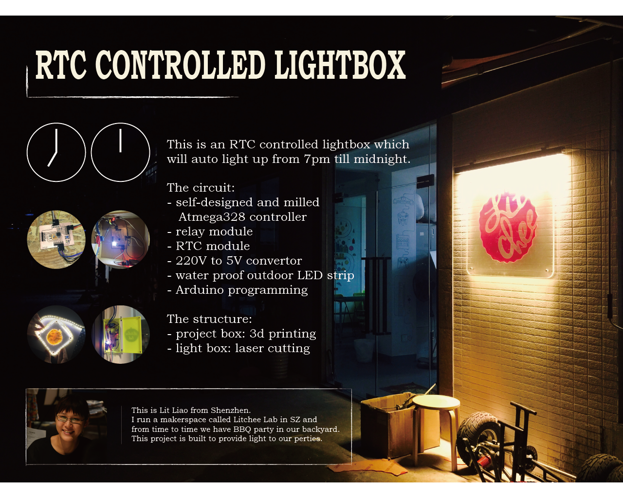
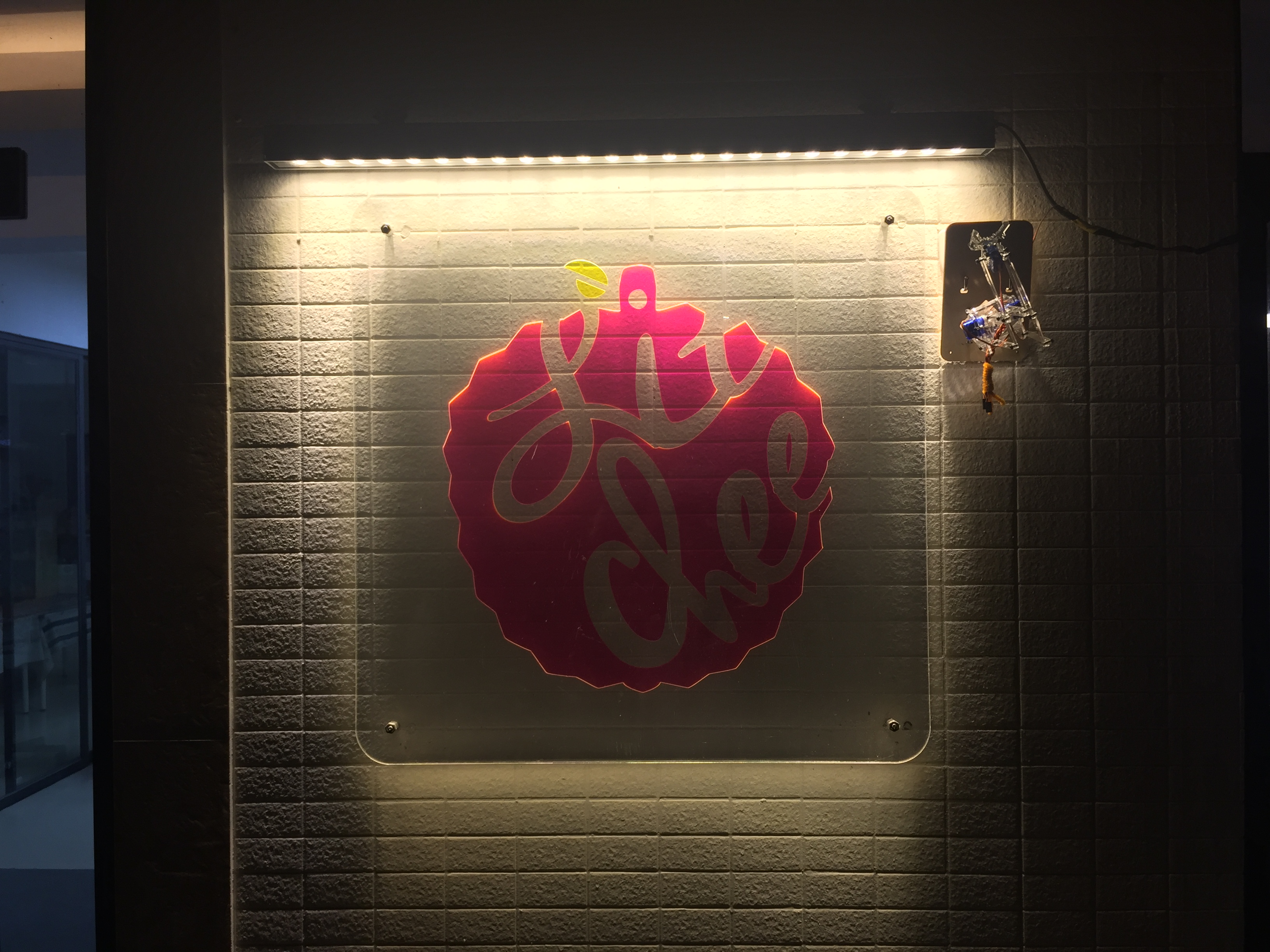
My final project is an RTC controlled lightbox. The original idea about this project is I want to DIY somethings functional for our space. Our garden needs some lightings for a while. So I decided to make a lightbox for it.
|| The plan
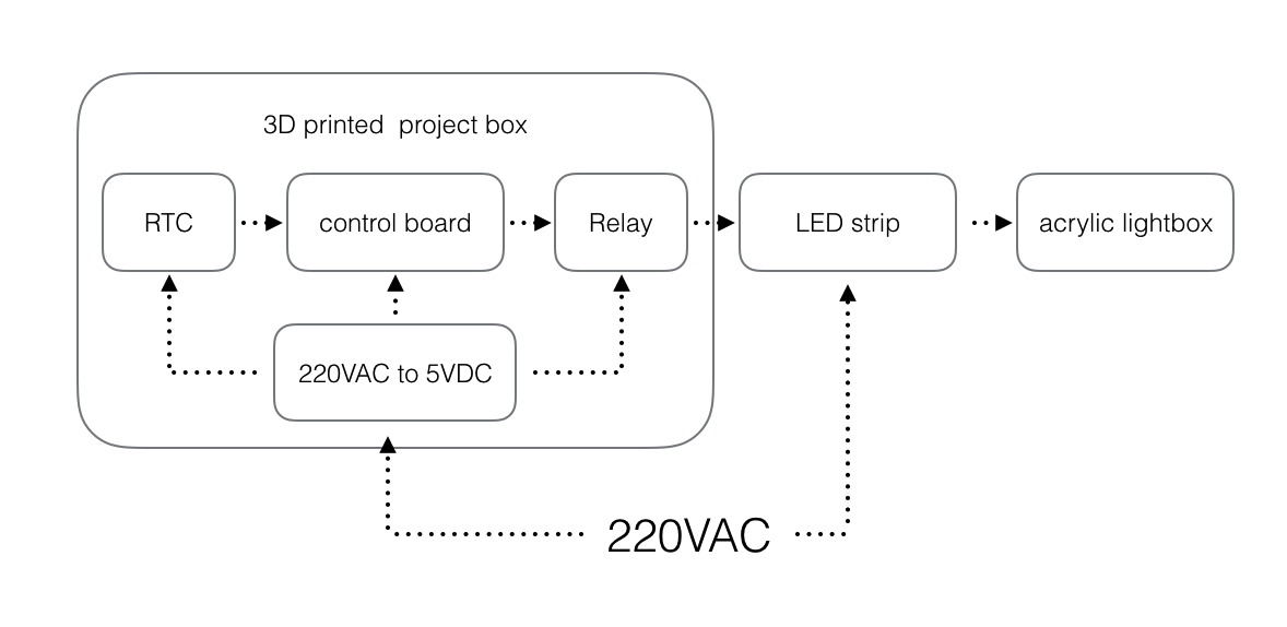
The whole project will include include parts as described below:
And here is the schedule of the all steps:
| STEP | TIMELINE | STATUS |
|---|---|---|
| make a plan | Jun. 12th | Done |
| PCB design | Jun. 18th | Done |
| PCB production | Jun. 19th | Done |
| Programming | Jun. 20th | Done |
| structure: laser cutting | Jun. 21th | Done |
| structure: 3D printing | Jun. 24th | Done |
| slide & video | Jun. 22th | Done |
|| PCB design
After using Attiny44 and 45 as control chips for a few times, I decided to try atmega328, because in that case, I can use the Arduino library for RTC modules directly. To do this, I need the pin mapping of atmage 328.
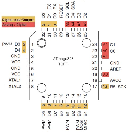
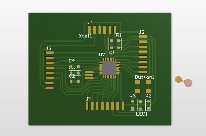
Here is the scheme of control board:

I used Altium as a PCB design tool. In this scheme, I made a mistake. Cause all components used in this circuit will be 1206, so I just use the 1206 capacitor symbols for all capacitor, resistor and LED.
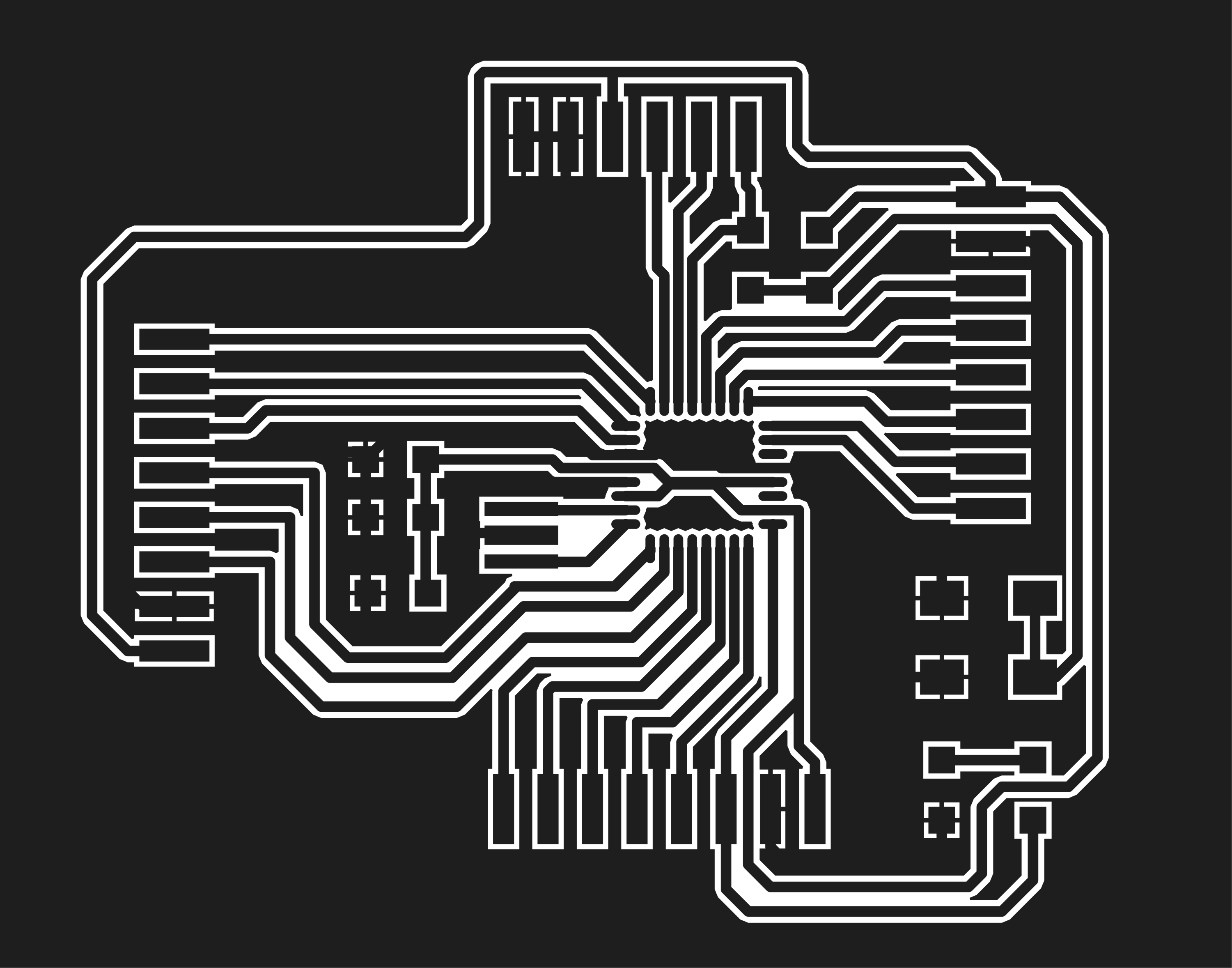
The PCB layout of this circuit board looks like this:
and here are the output file for the Fab modules to create .rml file:

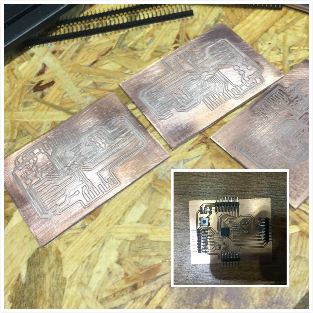
|| PCB Production
Because the pins of atmega328 are quite intense, I used the smallest endmill we have, 0.01 inch, to mill the board. And the endmill is quite easy to break, almost 1 endmill for 1-2 board. And after a few times, then I finally got the board I had expected.
|| Programming
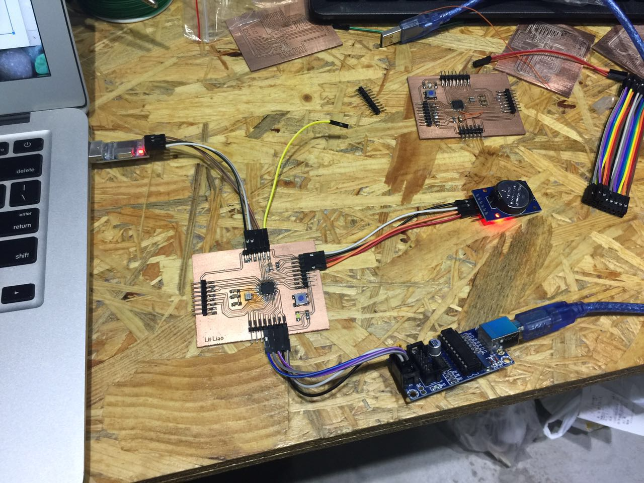
After soldering the board. Next step is burning the firmware to the board.
I used USBtinyISP as a tool to do that, and following is the connection:
I used Arduino IDE as a tool to upload firmware to the board. Here is the setting for this board:
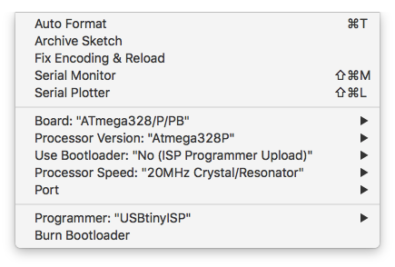
Click Burn Bootloarder, and here I can program it as a normal Arduino UNO. First I tried the Arduino 101 program, Blink. Here is the video:
I found a library for RTC module online for Arduino UNO. And added it to the sketch. The function of this sketch is turn the light on between 7PM and 24PM. Here is the sketch part:
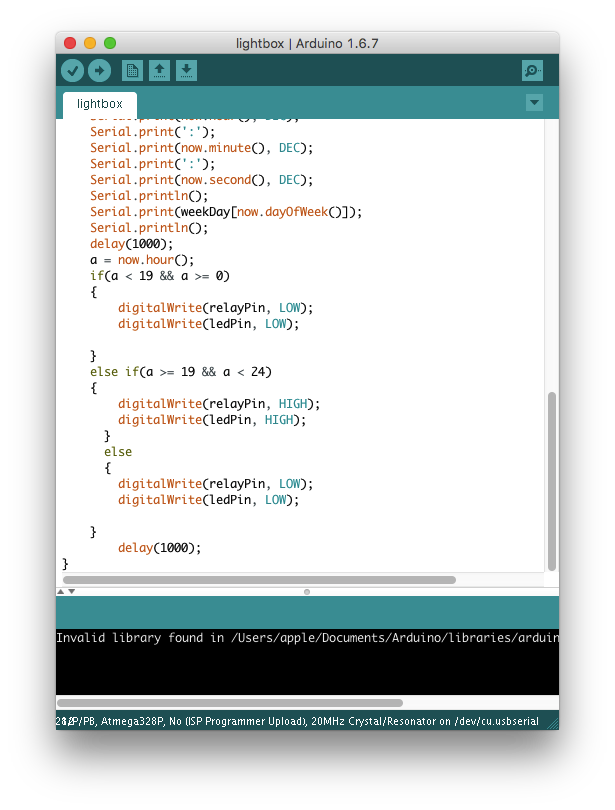
You can find the library and the sketch on the right.
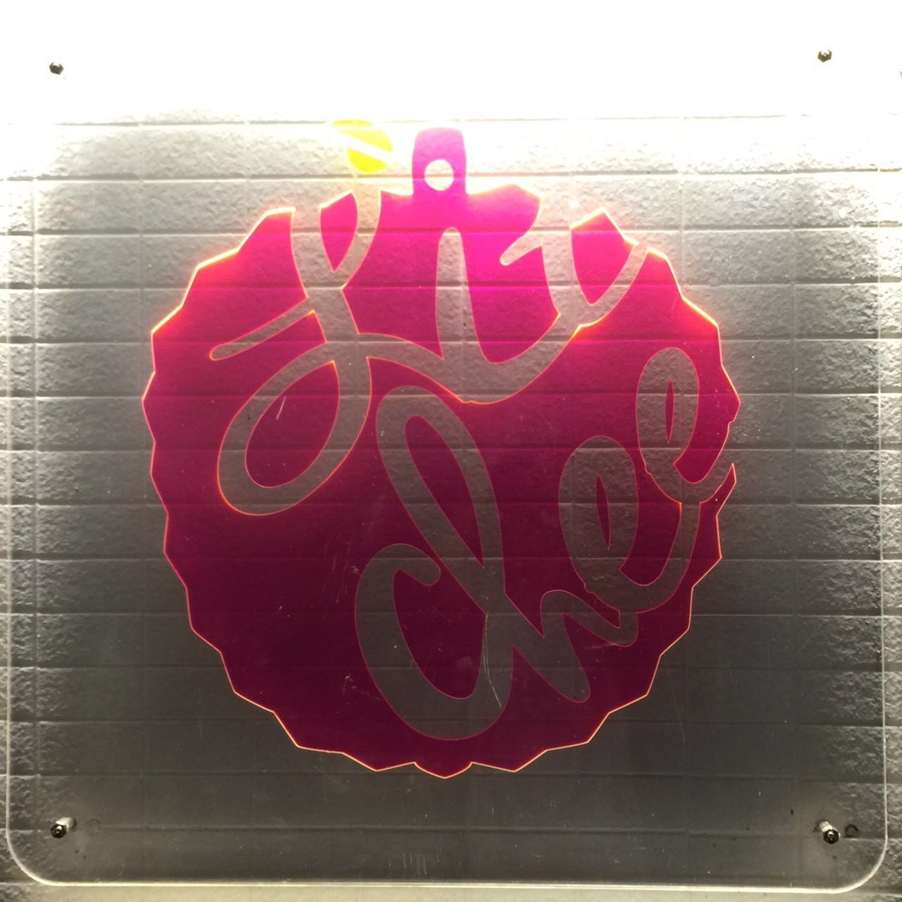
|| Structure: laser cutting
For this lightbox, I stacked a few sheets of fluorescent acrylic to the light box. You can find the design file on the right. and following is the picture of the lightbox.
|| Structure: 3D Printing
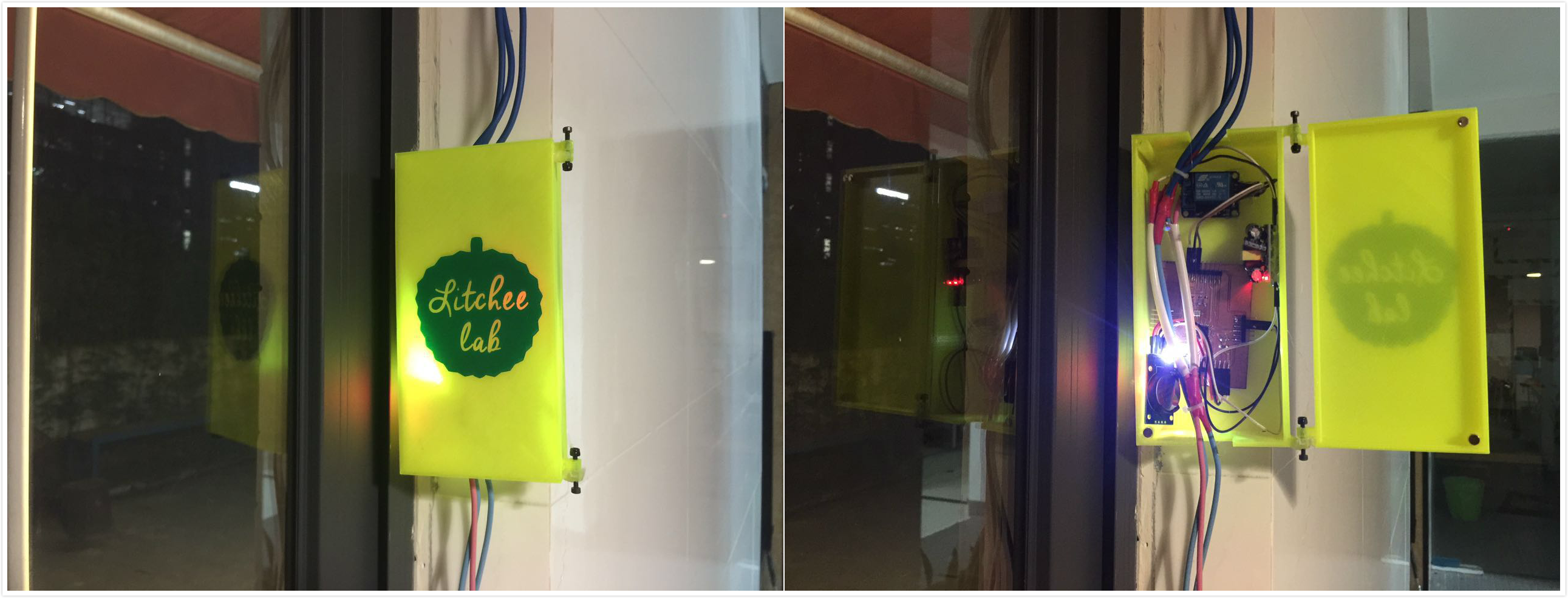
To protect the whole circuit, I made a project box for all modules also. I designed it using 123D design:
(pictures of the 3D model)I added 4 magnets to this box to make it easy to close. And here is how the box looks like after attached to the wall.
|| Update
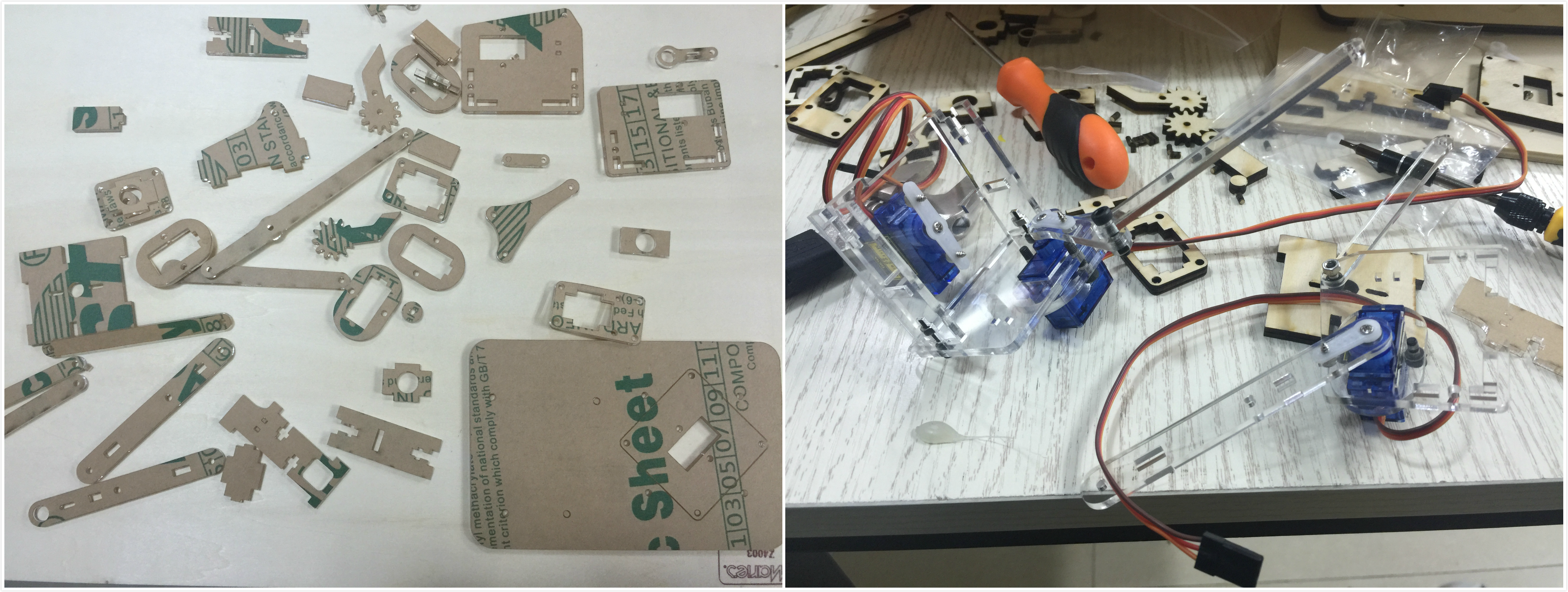
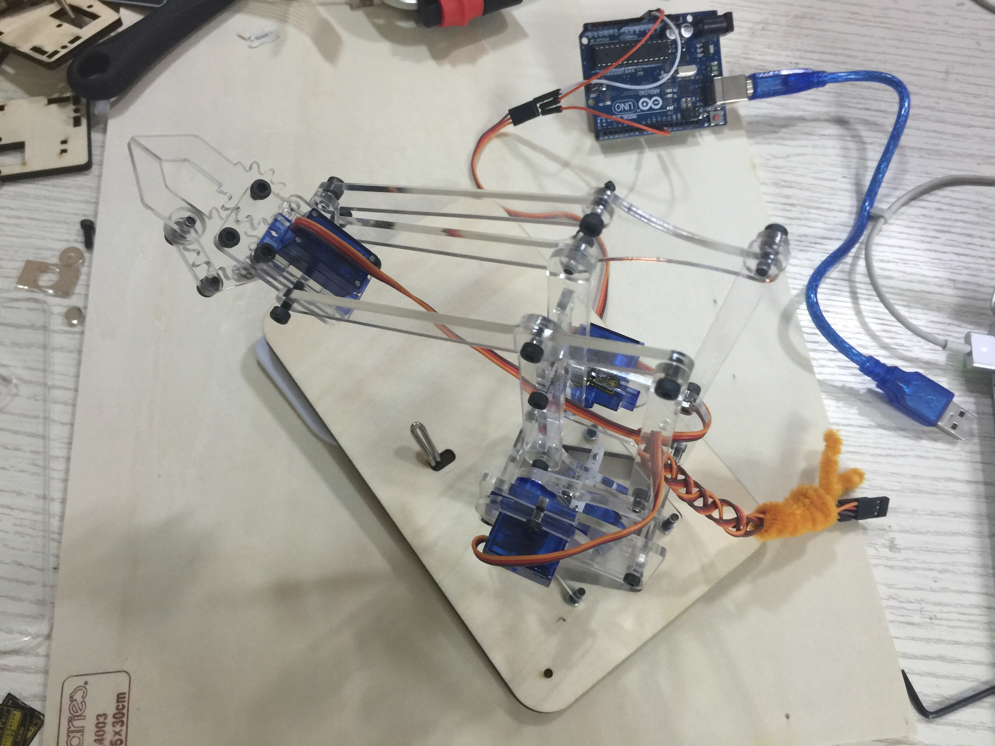
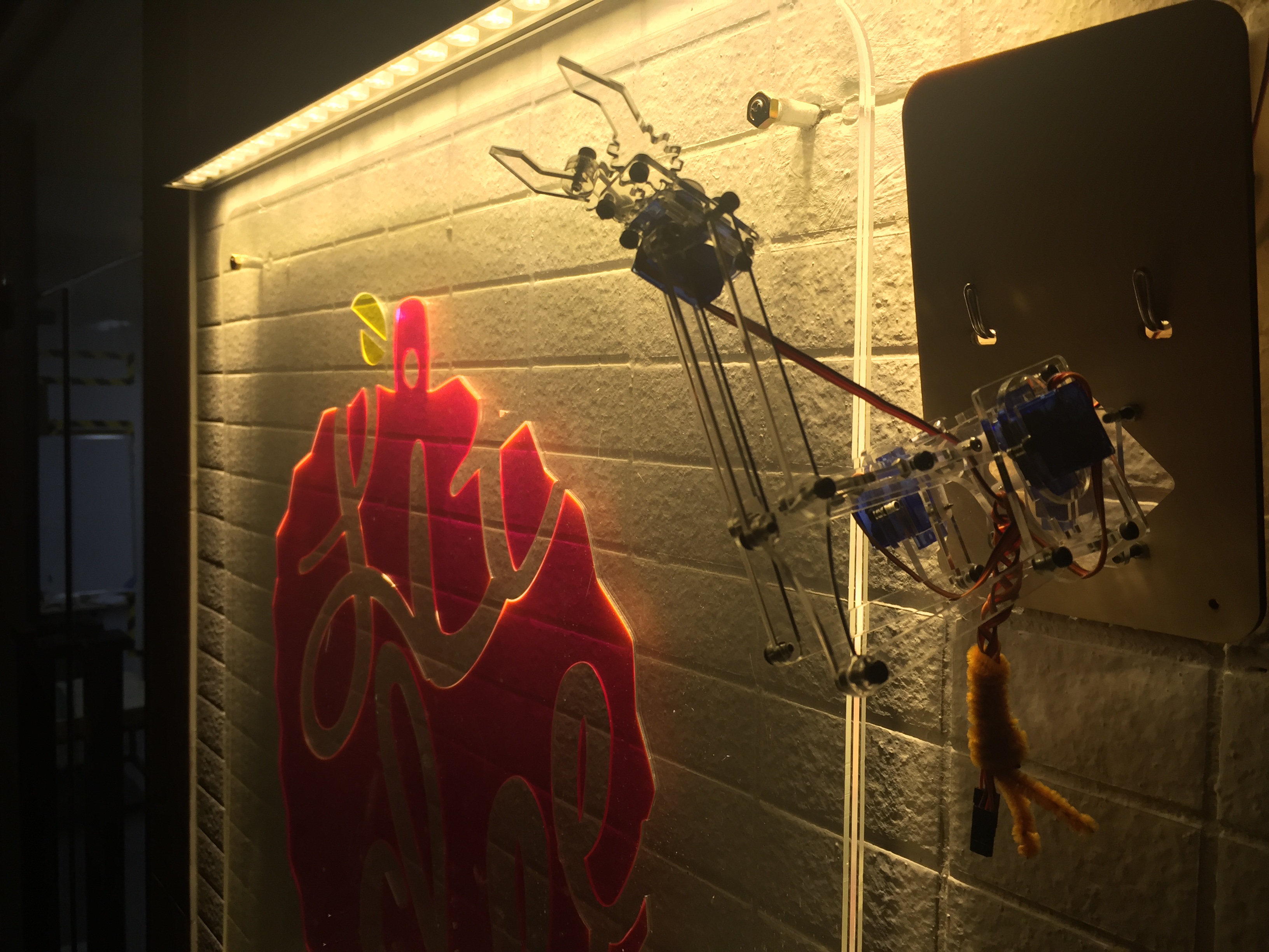
Some elements about tech that give people the correct expectation about makerspace is a must. So I added a robot arm to the light box to show that.
It's based on an open sourced project called MeArm. You can find their website on the right. I changed the design a bit to make it suitable for hanging against the wall.
|| slide & video
So here is the slide and video that describe the whole project:

This work is licensed under a Creative Commons Attribution 4.0 International License.