Week 12: input devices
April 13 - 19
Assignment
- Measure something: Add a sensor to a microcontroller board that you have designed and read it
Satschakit + Temperature Sensor
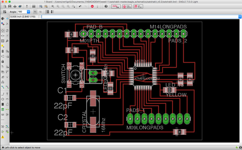
To create a microcontroller to handle the input signals, I decided to use Daniele Ingrassia's Satshakit as a base. I took the design and modified it so it could be milled by our Roland 40mx. Daniele's original design was done by fiber laser, so the tolerances were much tighter than the mill could handle. This modification was done easily in EAGLE.
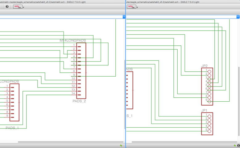
One major aspect of the edit was to split the header pins from one set into two, so that one of the traces that was running between them could do so with milling. The changes had to be first done on the schematics before I could take it to the board editing portion. All in all this process did not take too long and was rather straightforward.
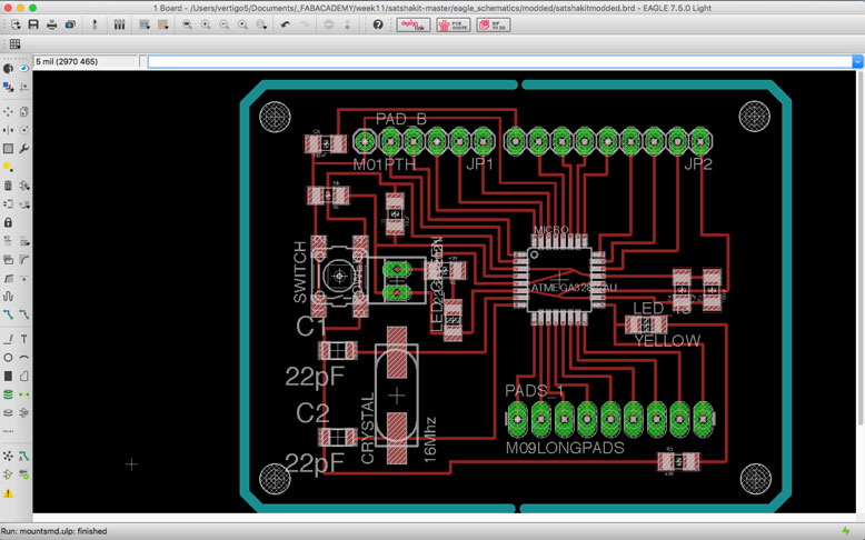
I added a few mounting holes as well.
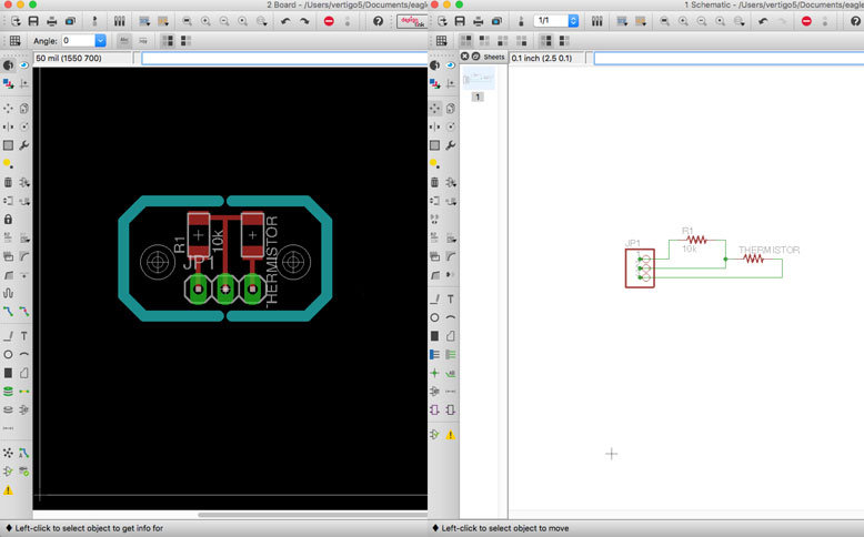
Once this was done, I went on to my input device. To integrate this assignment to my final project, I chose to use a thermistor to measure air temperature. I took a look at the schematics and it was very simple. All I needed was a 10k resistor, the thermistor itself, and three pins for ground, power, and signal. I used the schematic and code found from the Arduino site
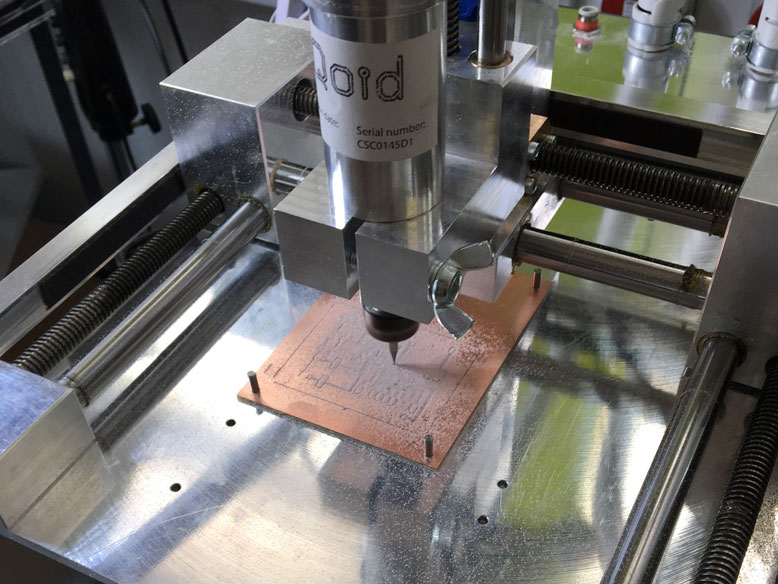
Creation of the satshakit board started once again with the cirqoid. The process has been covered in previous weeks.
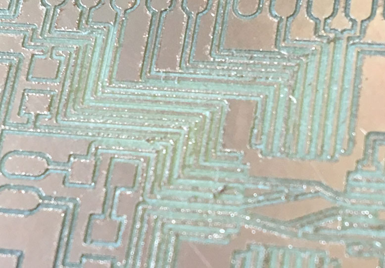
However, this time, the mounting was slightly loose and the vibrations caused a rather bad surface to the mill.
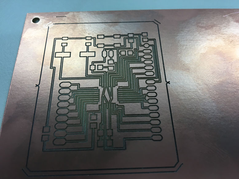
So I used some double sided tape to mount the board to the surface in addition to the mounting pins. The result is a much nicer board.
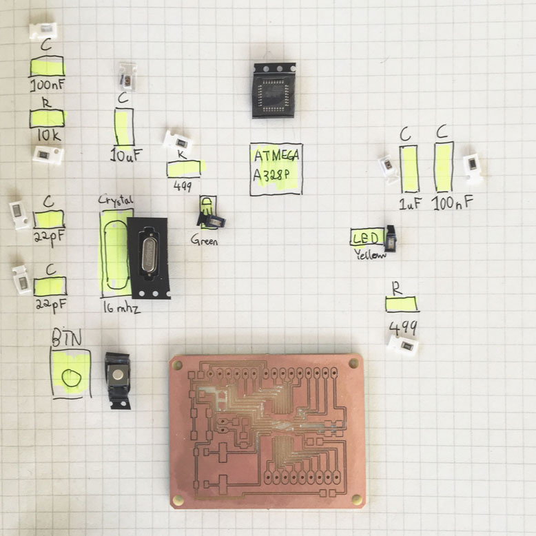
I took the required components I needed for the board and laid them out to make sure I had everything I needed. Everything was labled and placed in the relative positions that I needed them to be to prevent any mistakes.
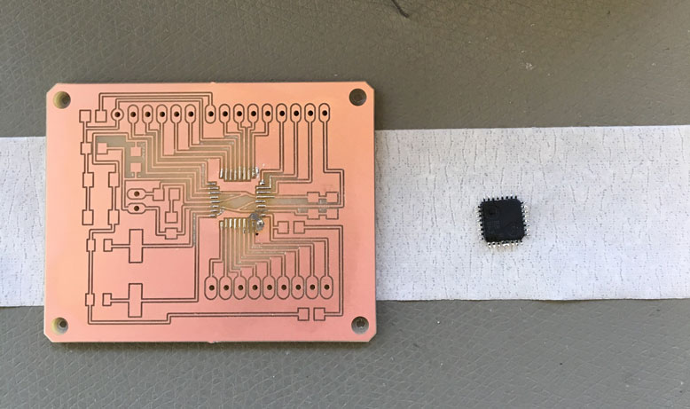
The hardest solder was the microchip itself. To achieve this, I decided to go with the heat gun method. To do this, I first tinned the contacts on the board and chip itself. I then placed the chip in place and used a heat gun with a small tip to melt the solder. It was important not to overheat the chip, thereby damaging it. The process worked well, with only a slight misalignment. However, the contacts were good with no cross interference.
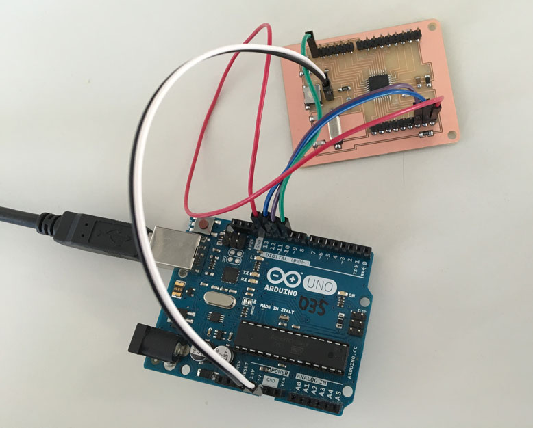
After all the other components were soldered on, I followed the directions on the satshakit github to use an arduino to program the chip.
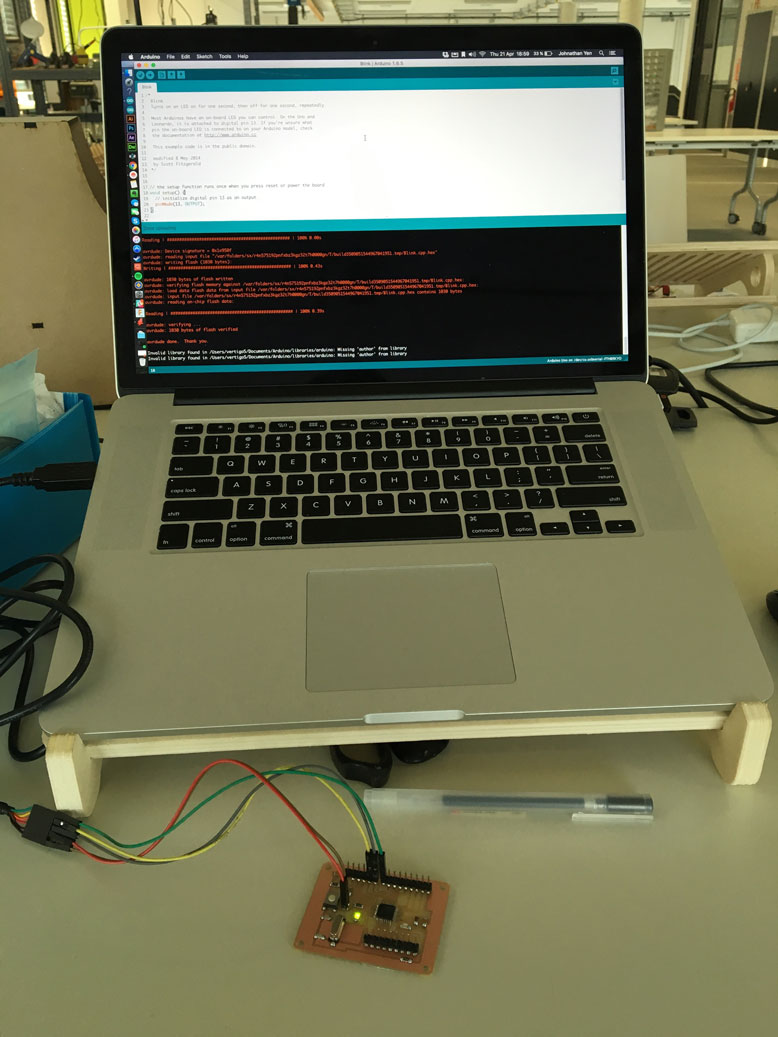
At first the chip could not be programmed. I soon found out that one of the capacitors I used for the board, was incorrectly labled from the factory. So after I switched those out, the board was able to be programmed without problem. I now had my very own satshakit!
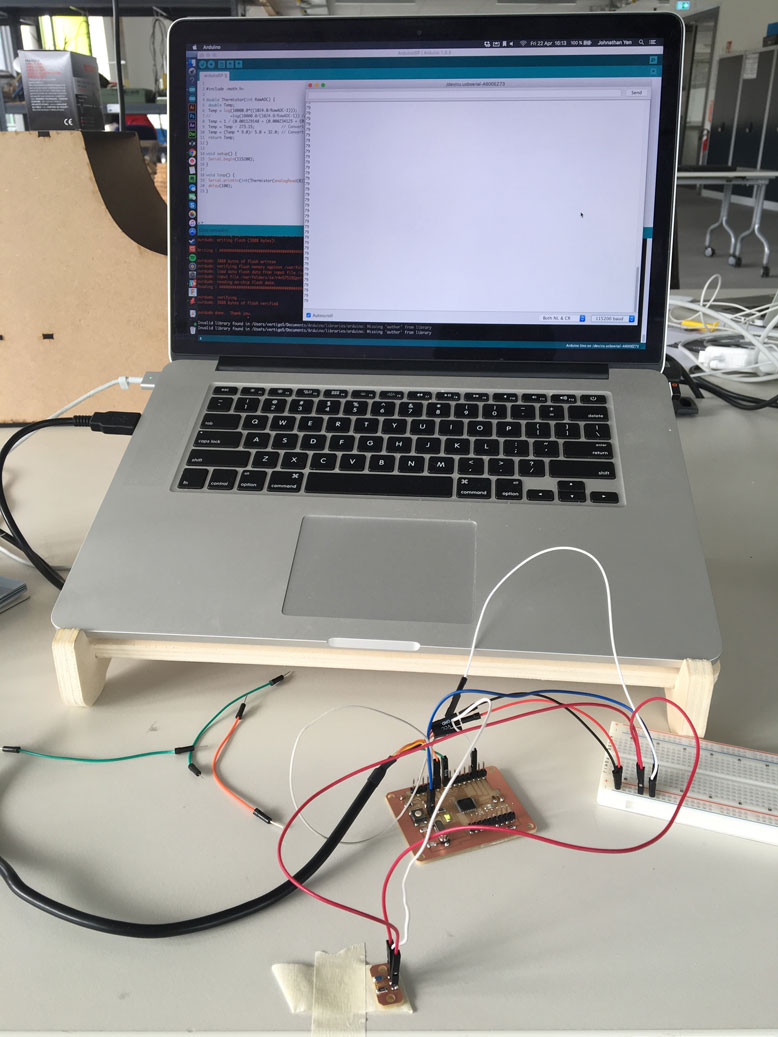
I then milled out the simple thermistor component and attached it to an anologue port on the satshakit. I did some tests using the code from the Arduino site, and it functioned very well.
Arduino Basic Thermistor Code:
#include <math.h>

double Thermistor(int RawADC) {
 double Temp;
 Temp = log(10000.0*((1024.0/RawADC-1)));
//         =log(10000.0/(1024.0/RawADC-1)) // for pull-up configuration
 Temp = 1 / (0.001129148 + (0.000234125 + (0.0000000876741 * Temp * Temp ))* Temp );
 Temp = Temp - 273.15;            // Convert Kelvin to Celcius
 Temp = (Temp * 9.0)/ 5.0 + 32.0; // Convert Celcius to Fahrenheit
 return Temp;
}

void setup() {
 Serial.begin(115200);
}

void loop() {
 Serial.println(int(Thermistor(analogRead(0))));  // display Fahrenheit
 delay(100);
}
The thermistor in action: