Step 1
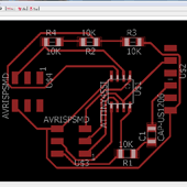
I choosed to redraw the HelloTemp board because it is a part of my final project
I needed the temp sensor to be separate from the board because the sensor must be in the heating box but i wanted to protect the electronic parts from the heat
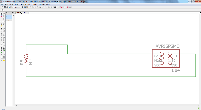
I drew the boards in Eagle : files here
source
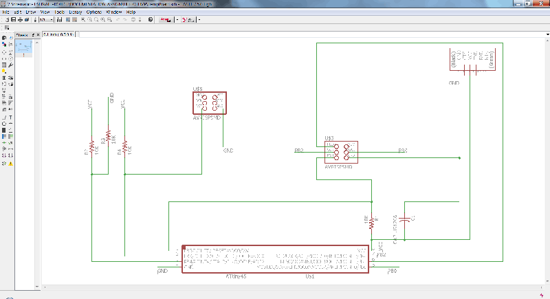
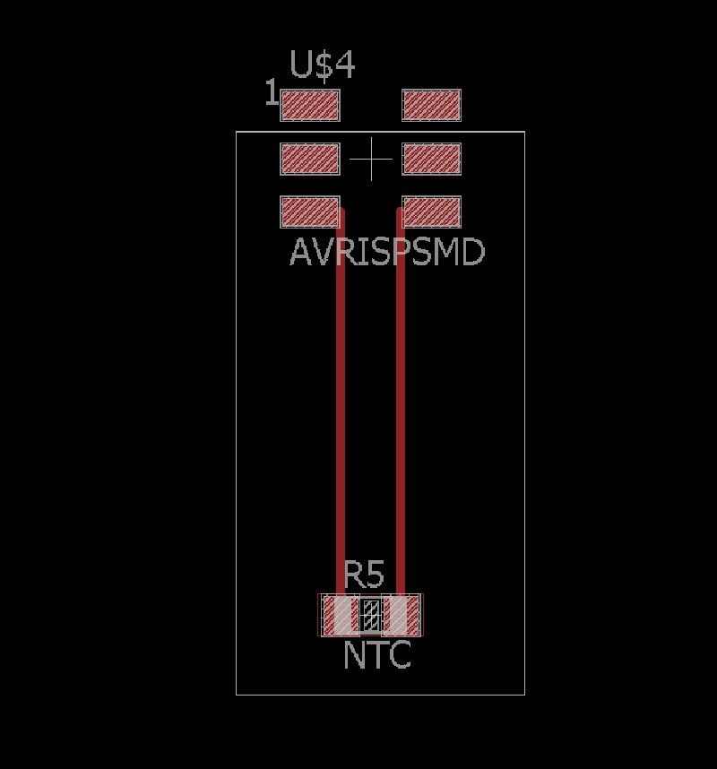
And the separate Sensor board
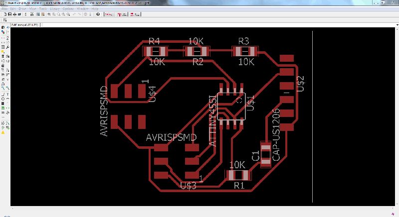
I used the dimension layer in Eagle to cut a part of unusefull traces, before to discover there was 2x2 pins headers in th fab Librairie...
I show it because i had many issues with dimensions of boards in Eagle
To me the simple and most efficient way is not to draw the line for cutting, but to move the borders of frame created around the board
when you "switch to board" from the schematic. You export this line in .png and it will give you a parfect result with the fabmodules
Whatever, i know i have to learn how to draw my traces in Eagle
Another way to draw the outline is with a vectorial 2D sofware like Inkscape or Illustrator
This is how i drew the final outline of the sensor board bellow, but i broke it quite fast so i choosed the previous version
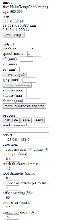
I milled the boards with a Modela 40, files here
Traces Settings, tool diameter : 0,1
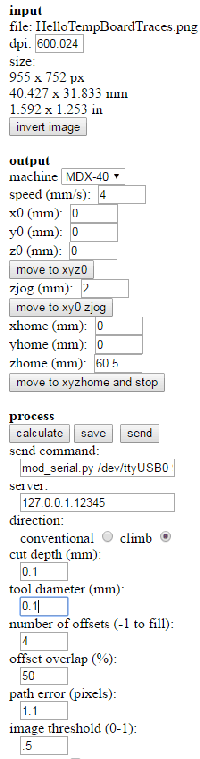
Cut Settings
Step 2
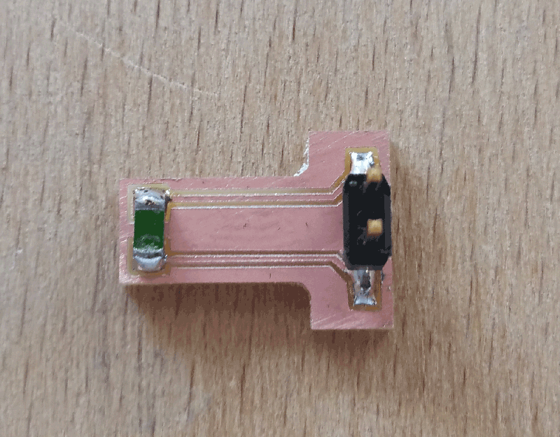
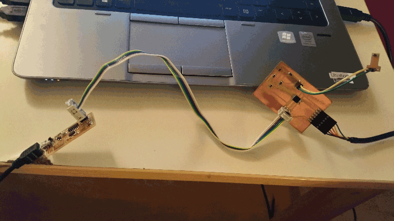
I stuffed the boards and plugged them
Step 3
This time i tried to program the Git cmd

Code bellow
C:\Users\adminpatxi>cd Desktop
C:\Users\adminpatxi\Desktop>cd TempMakeFile
C:\Users\adminpatxi\Desktop\TempMakeFile>ls
LIB hello.temp.45.c hello.temp.45.make hello.temp.45.py
C:\Users\adminpatxi\Desktop\TempMakeFile>make -f hello.temp.45.make program-usbt
iny
avr-gcc -mmcu=attiny45 -Wall -Os -DF_CPU=8000000 -I./ -o hello.temp.45.out hello
.temp.45.c
avr-objcopy -O ihex hello.temp.45.out hello.temp.45.c.hex;\
avr-size --mcu=attiny45 --format=avr hello.temp.45.out
AVR Memory Usage
----------------
Device: attiny45
Program: 428 bytes (10.4% Full)
(.text + .data + .bootloader)
Data: 0 bytes (0.0% Full)
(.data + .bss + .noinit)
avrdude -p t45 -P usb -c usbtiny -U flash:w:hello.temp.45.c.hex
avrdude: AVR device initialized and ready to accept instructions
Reading | ################################################## | 100% 0.02s
avrdude: Device signature = 0x1e9206
avrdude: NOTE: FLASH memory has been specified, an erase cycle will be performed
To disable this feature, specify the -D option.
avrdude: erasing chip
avrdude: reading input file "hello.temp.45.c.hex"
avrdude: input file hello.temp.45.c.hex auto detected as Intel Hex
avrdude: writing flash (428 bytes):
Writing | ################################################## | 100% 0.43s
avrdude: 428 bytes of flash written
avrdude: verifying flash memory against hello.temp.45.c.hex:
avrdude: load data flash data from input file hello.temp.45.c.hex:
avrdude: input file hello.temp.45.c.hex auto detected as Intel Hex
avrdude: input file hello.temp.45.c.hex contains 428 bytes
avrdude: reading on-chip flash data:
Reading | ################################################## | 100% 0.24s
avrdude: verifying ...
avrdude: 428 bytes of flash verified
avrdude: safemode: Fuses OK
avrdude done. Thank you.
And there the war started, PYTHON, ANACONDA, NUMPY and many more. What i liked is that it tells you what is wrong
Everything in this file
Step 4
The test
Step 5
I did it twice because i broke the board.
The second time i programmed it with IDE arduino and i simply pasted the C code in the IDE before to upload it on the chip, then i launched python's graphics
C code here