Step 1
I downloaded the Hello World board files neededhere
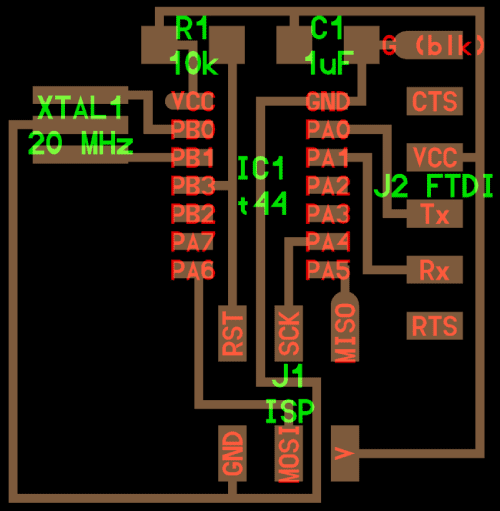
Then i was able to make a list of the needed components
A 20 MHz Resonator, a 10k Resistor, a 1uF Capacitor, a Attiny 44, a ftdi-sm-header, and a AVRISPMD, a 6x6mm switch and a 1206 LED. The 20 Mhz Crtistal is optional, i will use the 8 Mhz internal clock of the chip
Step 2
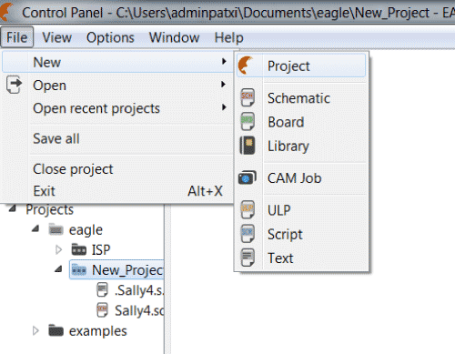
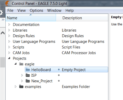
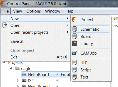
I created a new project called HelloBoard in Eagle
Step 3
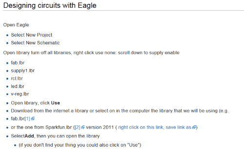
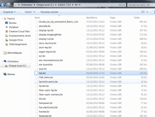
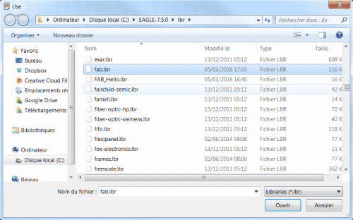
i downloaded the fab.lbr library and copied it into the Eagle library folder here
Step 4
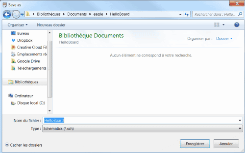
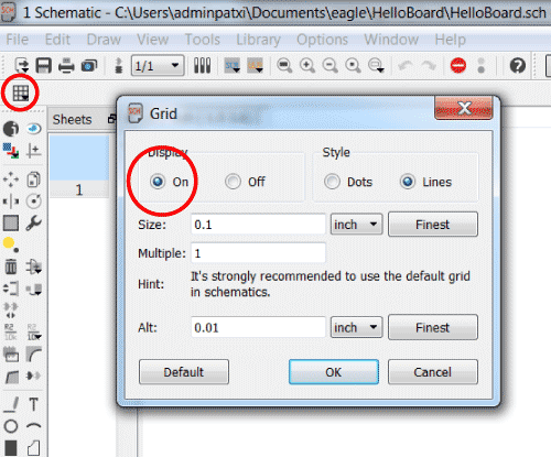
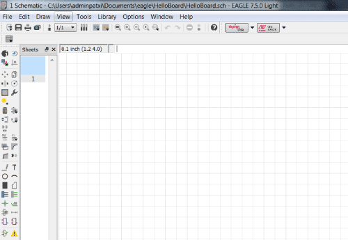
Back in Eagle i created a new schematic, i saved it and i displayed the grid to make things easer
Step 5
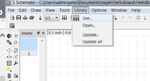
I went to the library settings to choose the fab library and i created my components on the grid
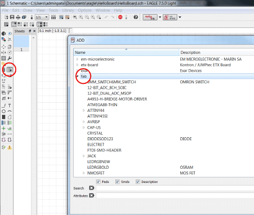
To add a component select it in the library and click "OK". Then you can place you component (right click to turn it) and click left to put it on the grid
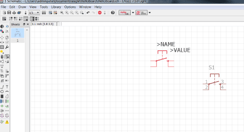
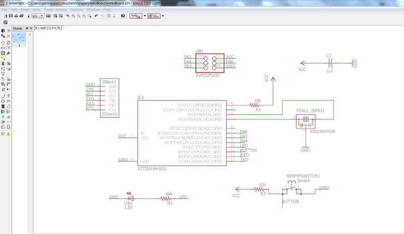
Link them, add the labels and values, and add the led the button and the resistor (note that it shouldn't be a 499 but i know i have one in 1206 that will do the job)
Step 6
I switched to board, placed the components, and used the auto-routing command to get a board
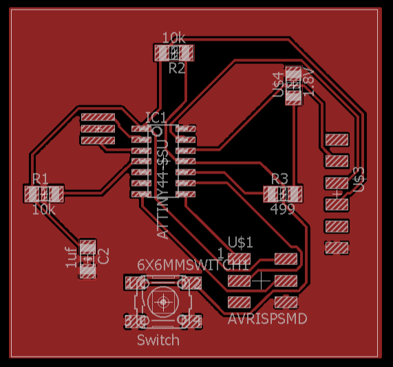
Then i entered my milling machine rules in the DRC (The ERC was ok) and i checked the board : No problemo
I didn't milled the board because i want to be sure i'll do it for the good components
Step 7
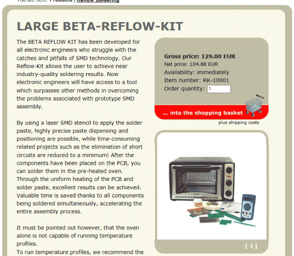
At the lab we have a very cool reflow hoven from Beta Layout that works really well, and i wish to do my soldering with it
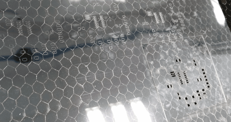
The only thing missing is the way to produce the stencils, so i made some (succesfull) tries
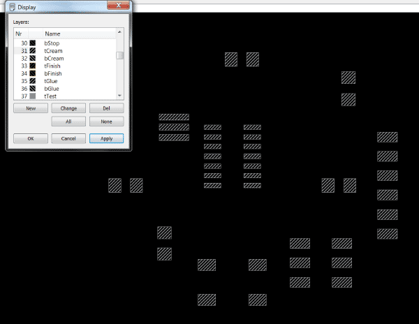
So i exported in .dxf from Eagle the pads of my board (to do so just display the tCream layer in Ealge before to export)
The plotter was not strong enough to cut the 0.14mm Acetate film, so i tried it with the Laser cutter
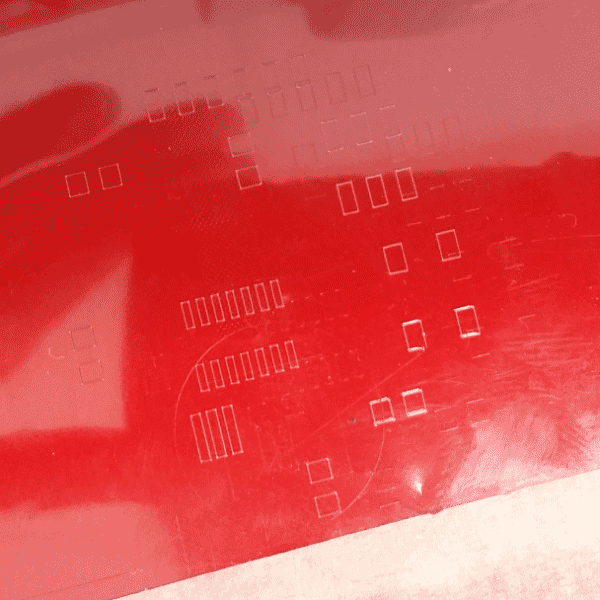
After a few ones, i've found the good setting (30% speed / 4% power)
Step 8
Now we have the needed components, so i stuffed a first board milled with the CIF, but i haven't been able to program it
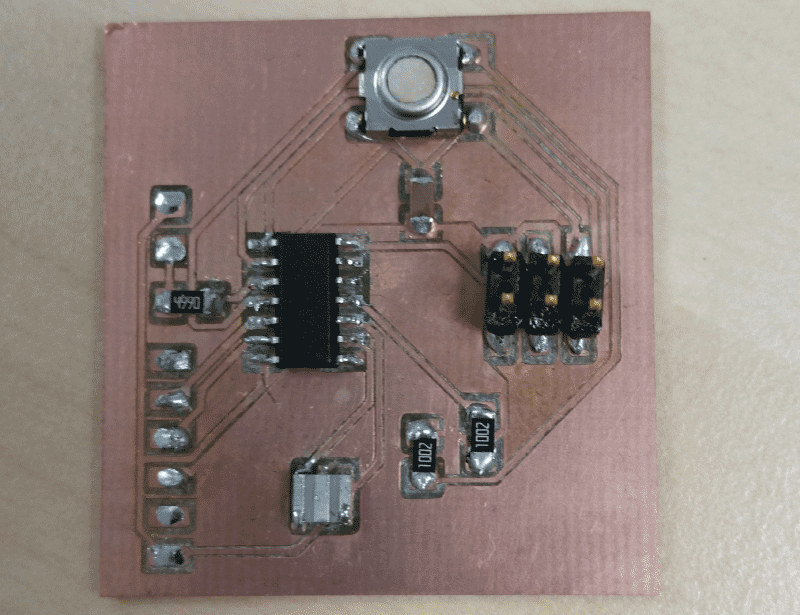
I tried to look at every Solder, i changed some components but i've found no way to program it
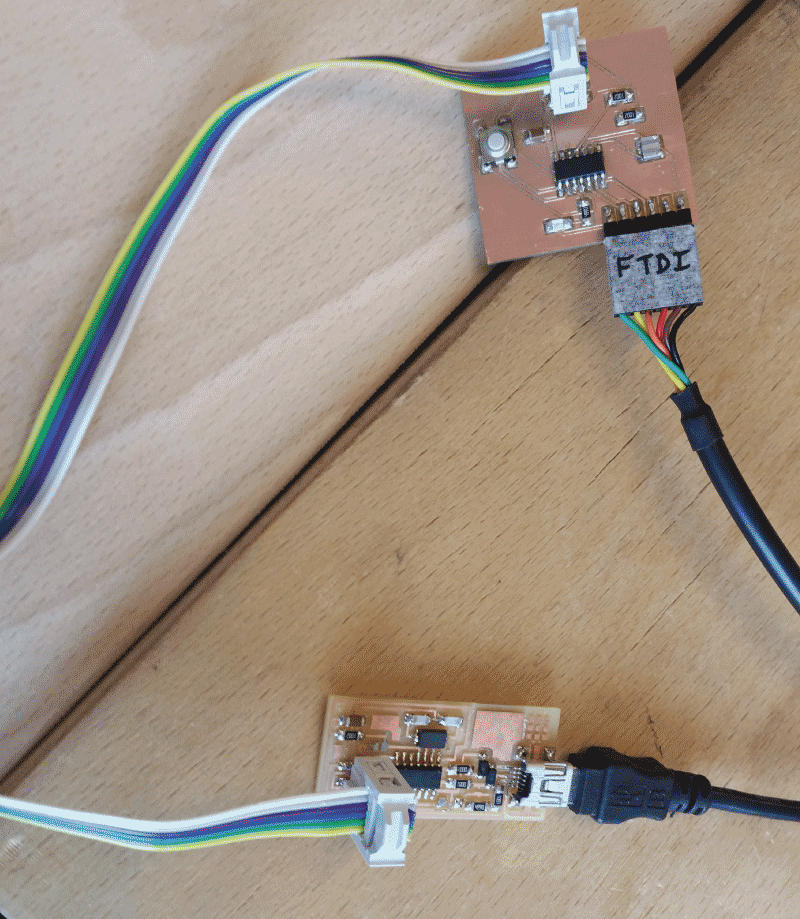
So then i did an other board (with modela and fab module). I stuffed it, but there was a cutted trace, so i did a bridge with a cable to fix it.
I tried to program it another time but i still received the same error message.
C:\>cd dev\Hello
c:\dev\Hello>make -f hello.ftdi.44.echo.interrupt.c.make
avr-gcc -mmcu=attiny44 -Wall -Os -DF_CPU=20000000 -I./ -o hello.ftdi.44.echo.interrupt.out hello.ftdi.44.echo.interrupt.c
avr-objcopy -O ihex hello.ftdi.44.echo.interrupt.out hello.ftdi.44.echo.interrupt.c.hex;\
avr-size --mcu=attiny44 --format=avr hello.ftdi.44.echo.interrupt.out
AVR Memory Usage
----------------
Device: attiny44
Program: 790 bytes (19.3% Full)
(.text + .data + .bootloader)
Data: 74 bytes (28.9% Full)
(.data + .bss + .noinit)
c:\dev\Hello>make -f hello.ftdi.44.echo.interrupt.c.make program-usbtiny-fuses
avr-objcopy -O ihex hello.ftdi.44.echo.interrupt.out hello.ftdi.44.echo.interrupt.c.hex;\
avr-size --mcu=attiny44 --format=avr hello.ftdi.44.echo.interrupt.out
AVR Memory Usage
----------------
Device: attiny44
Program: 790 bytes (19.3% Full)
(.text + .data + .bootloader)
Data: 74 bytes (28.9% Full)
(.data + .bss + .noinit)
avrdude -p t44 -P usb -c usbtiny -U lfuse:w:0x5E:m
avrdude: initialization failed, rc=-1
Double check connections and try again, or use -F to override this check.
avrdude done. Thank you.
make: *** [program-usbtiny-fuses] Error 1
Next step in Week 8 : Embedded programming
I was really hopping to test reflow but i don"t have time for this now
Now we have the needed components, so i stuffed a first board milled with the CIF, but i haven't been able to program it
Step 9
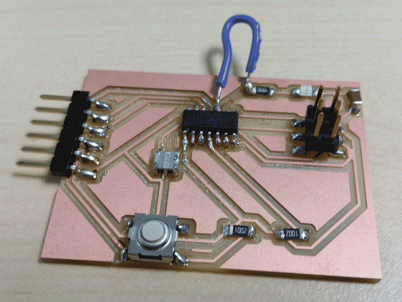
After many trys without understanding what was wrong i decided to do another board
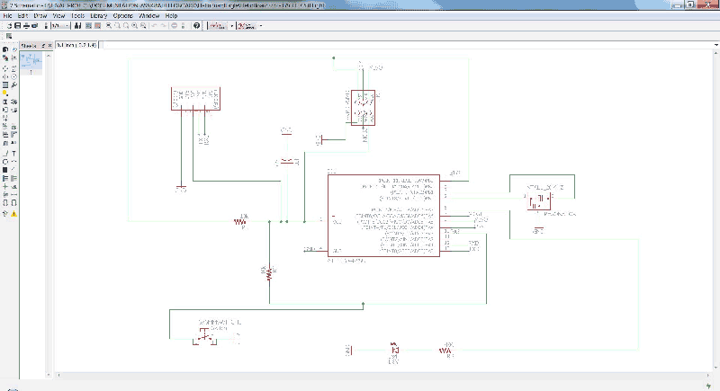
I designed it again in Eagle
Schematic
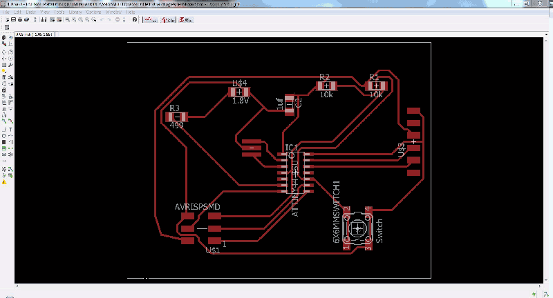
Board
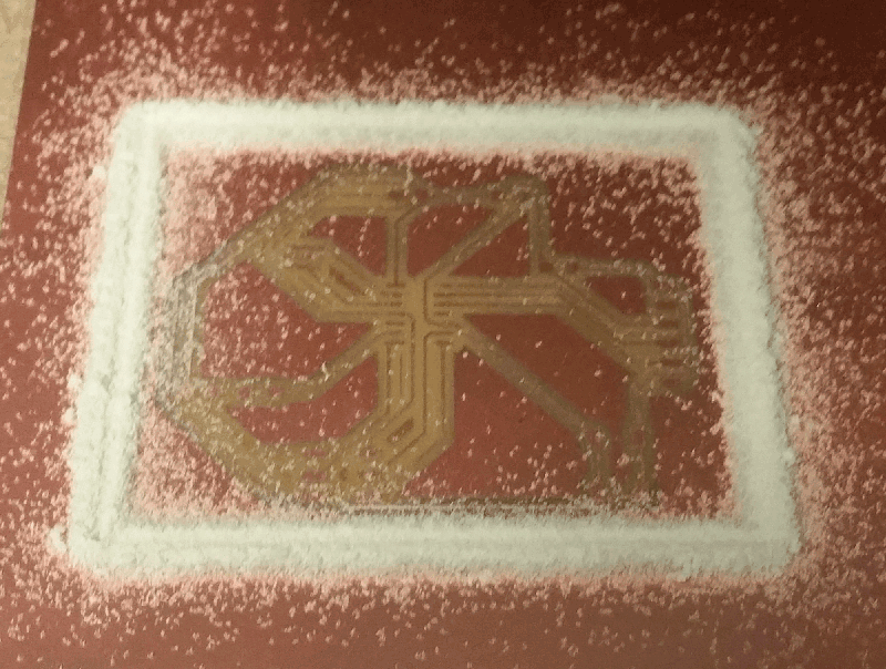
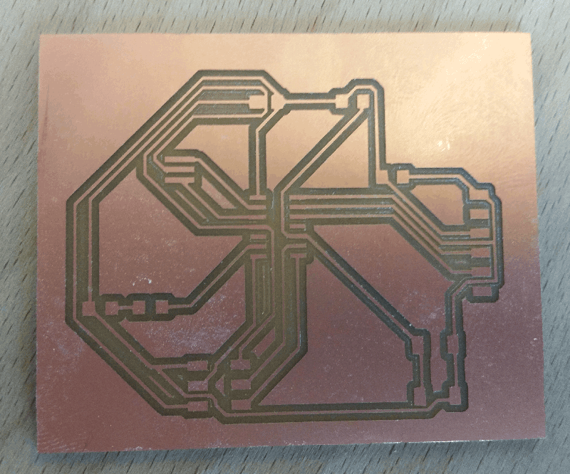
Step 10
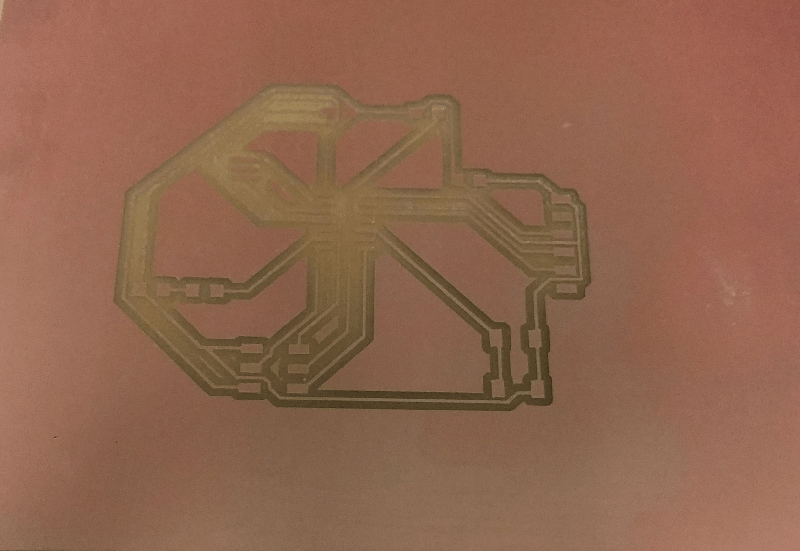
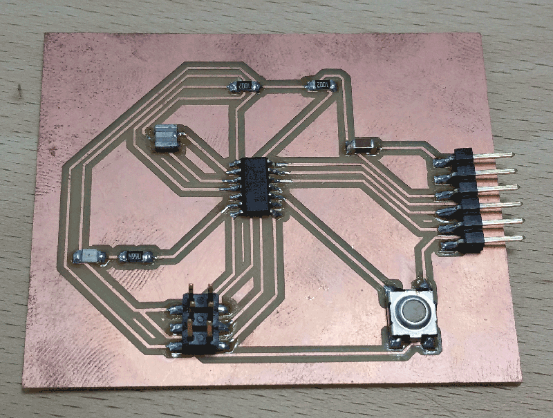
Then i milled it with Modela 40 and stuffed it
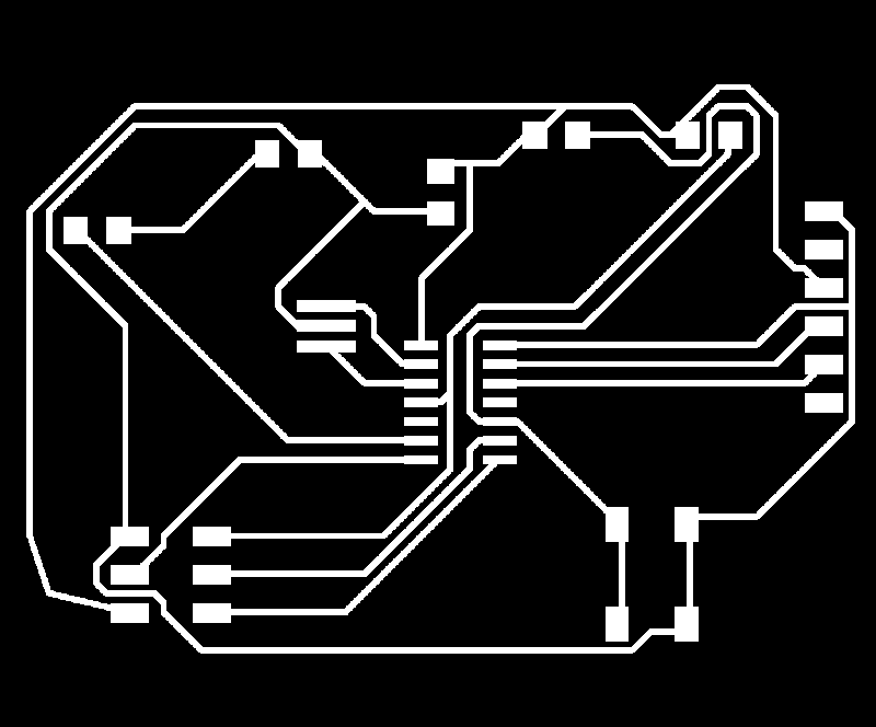
Fabmodule Files
Step 11
I choosed to try an other way to program the board with the Arduino IDE
I first needed to downaload and install the ATtiny44/45/84/85 librairie (Link below)
Librairies
I plugged and linked my FabISP and the Hello Wolrd Board to the laptop and i choosed the settings matching with my board in the IDE's tool settings
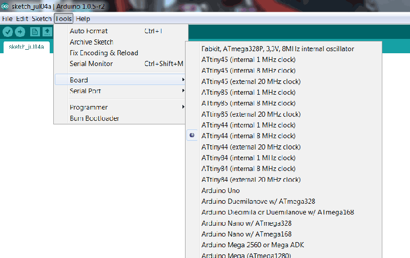
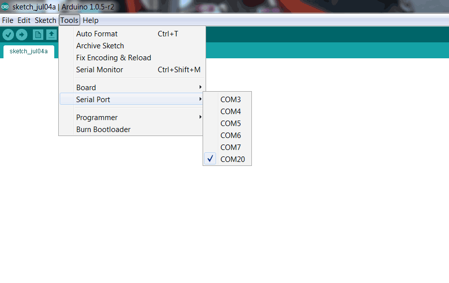
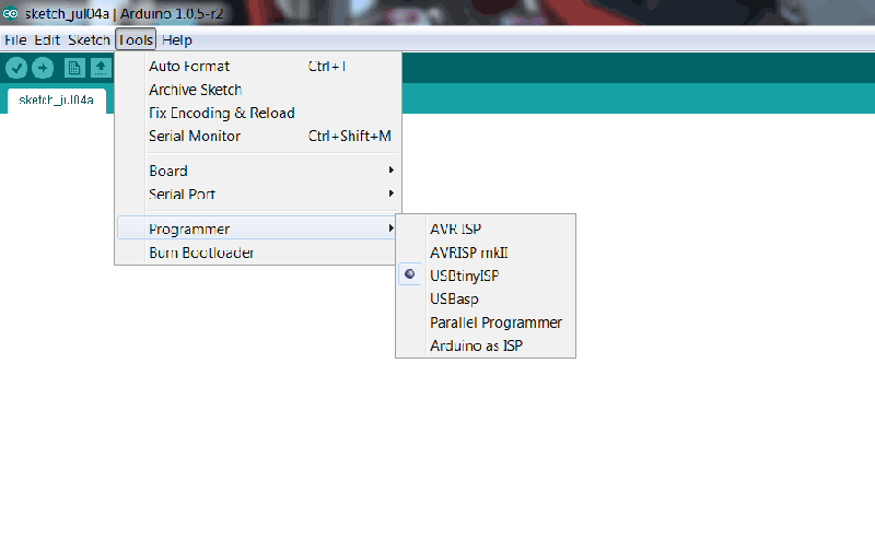
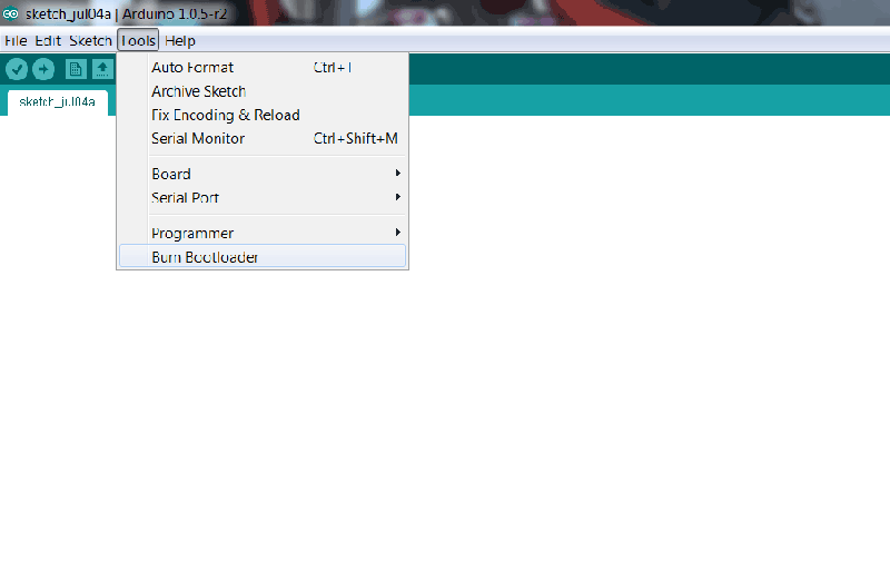
Step 12
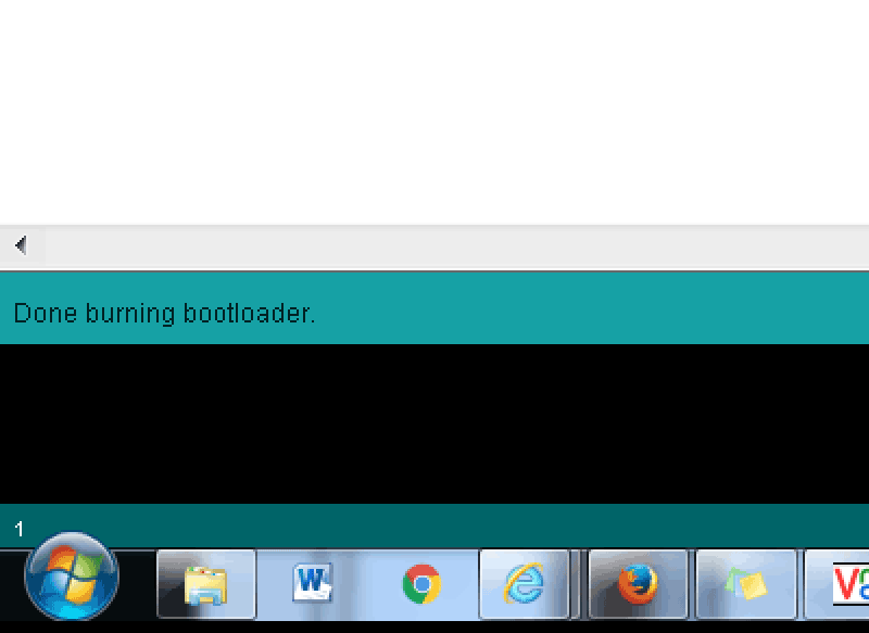
Finaly i tested the simple "Button" example from Arduino IDE (mind the pins configuration with your chip Data-sheet and Eagle files)
Arduino file
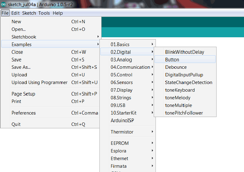
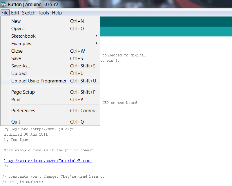
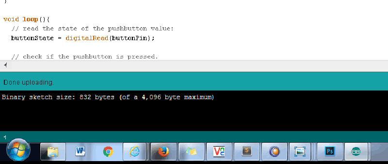
And it was find