WEEK|13
Output
For this week, we had to design a board wich will output something (turn a motor, light a LED, launch a nuclear weapon...)
Software used
- KiCAD
- Code::Blocks
- Arduino IDE
Source files
Did I do that elsewhere ?
Here is the assignements where I had to use these skills :
My idea
By lack of time, I choosed to use my board made during Week 6 and use it to turn one or two stepper motors.
But as we need to make a board, I designed a little PCB witch will be used both as an interface with my "arduclone" and as support for a Pololu stepper driver I already own
This would be used (as-is or a variant) in my final project
My first idea
Before the simplier idea, I had the goal to make a "gestalt" like board, with a AVR on it, receiving commands from a main MMCU via an I2C bus, and turning motors according to them. It would need too much work to be faisible in only one week, so I keep this idea for the project developpement.
In the past
Week 11
In Week 11, I've done a board witch use a sensor, but there is also two LED/Laser driven with only one pin, using Charlieplexing, so this techncally can be considered as an output device :-)
ARC Reactor prop

Long before the FabAcademy, I designed a little circuit (made using SeedStudio), witch drives a tens of LED using two 555 timer, a decimal counter and persistence of vision.
The first 555 was in monostable mode, triggered by a micro switch. He feeds power for the second 555 in astable, witch triggers the decimal counter a a few hundreds of hertz. The outputs of the decimal counter was all linked to pairs of LED witch was turned on quickly enough so there was no visible flickering. This design have a few flaws but worked well anyway. I am pretty proud of this design, because I wanted to not use any microcontroller for this simple task.
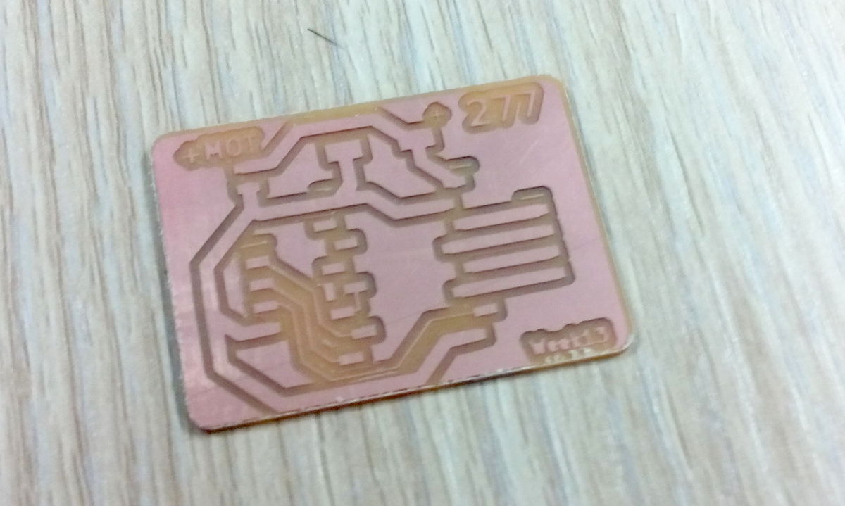
The design

I still used KiCAD to make this board. I take care to use thicker traces for the motor power lines.
To avoid catastrophic misconnection, I also added some polarity marks on the copper side. For a later design, I will add a fuse too (either a resetable or a old-style one, still don't know).
Again to reduce risks of shock, I will use female headers for the motor connection
The board
As always : KiCAD > SVG Export > Inkscape > PNG export > Fabmodules > vPanel
And this time, without any mistake \o/
In Fabmodules, I had set the "path error" to 1 to get more straight lines.
Hacking the headers
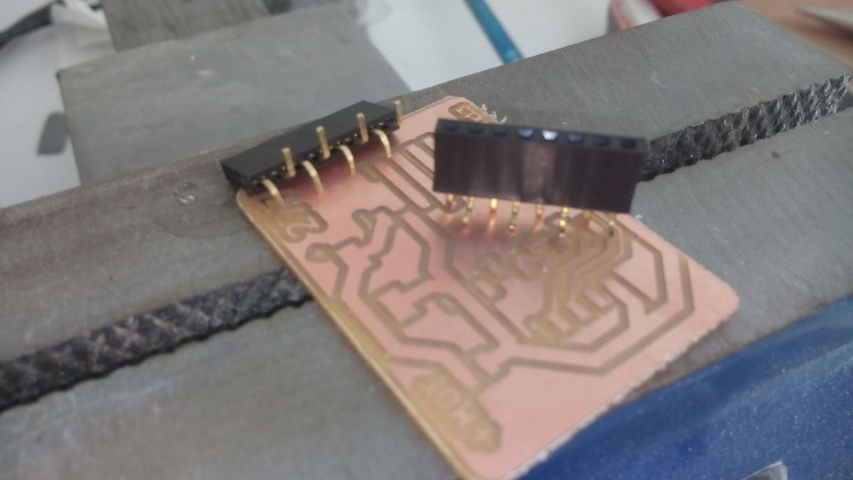
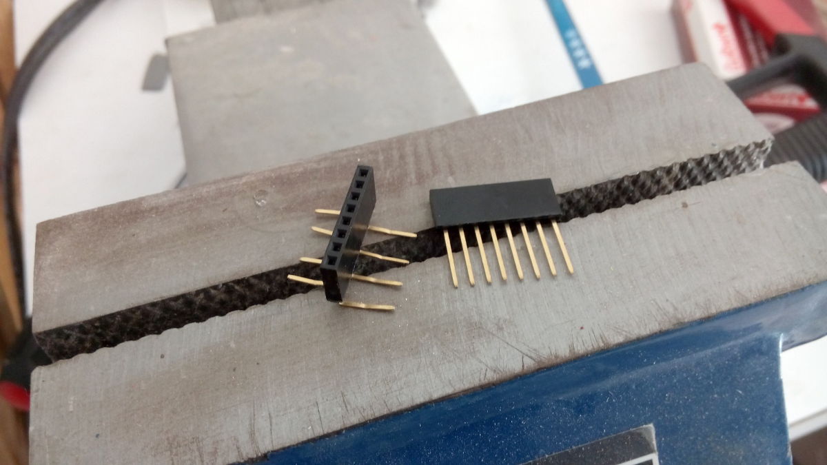
In the lab, we didn't had straight female SMD headers, so I took the throu-holes one and apply some magic on them using pliers.
Tricky, time consumming, but it worked very fine.
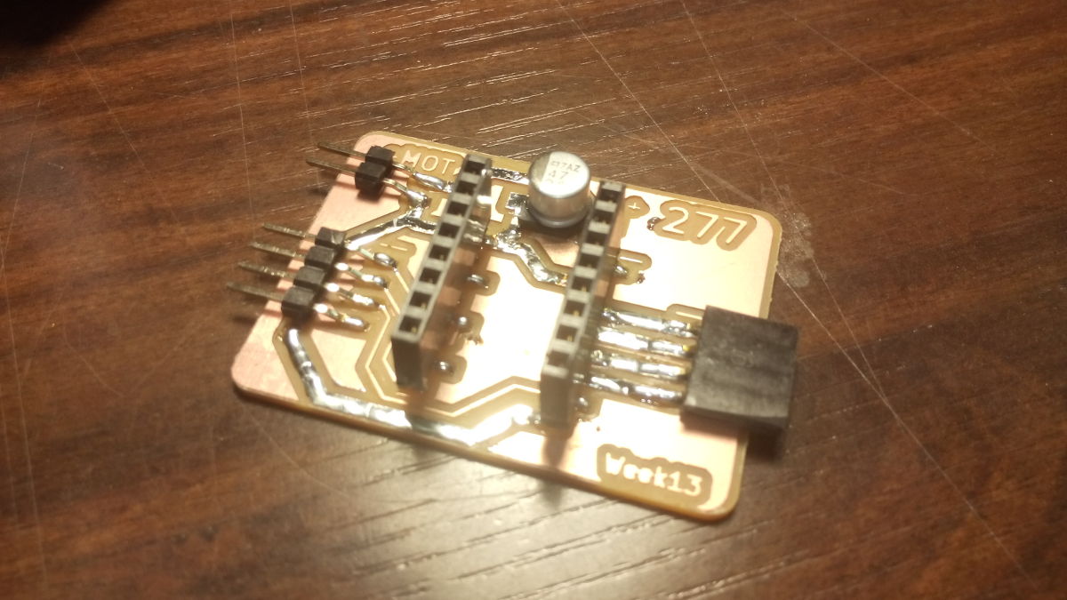
Soldering
Not much difficulties here
Programming
Here come the more difficult part.
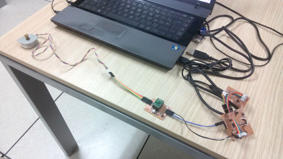
From left to right : a stepper motor, my board, myduino (week8), the FabISP.
This weeks assignement will be for me more on a software side than a hardware side.
Indeed, I want my board to drive the stepper driver with acceleration and decceleration.
I used this application note from Atmel as a reference, as well as this article to better understand how the AccelStepper library works
First trouble
AccelStepper is an Arduino library. This means that there is some function inside that are from the "arduino world", and "regular" C/C++ didn't know what to do with "micros()", "pinMode()" or "digitalWrite()" and all their constant.
So, my first thing was to add some compatibility. I wrote a "arduino_compatibility" file (along with its header) witch defines/rewrite missing arduino functions
I.e. : the "pinMode" function was rewritten :
void pinMode( uint32_t ulPin, uint32_t ulMode )
{
    switch ( ulMode ) {
    case INPUT:
        input(PORTD, ulPin);
        break ;

    case INPUT_PULLUP:
        input(PORTD, ulPin);
        digitalWrite(ulPin, HIGH);
        break ;

    case OUTPUT:
        output(PORTD, ulPin);
        break ;

    default:
        break ;
    }
}
As you can see, the function assumes that the pin is on Port D of the microcontroller, this simplify the code, and for this particular case, it isn't a problem.The caveat is that it makes those functions more difficult to port on another board.
For the "micros()" function, I used this article to recreate the function
Testing my code
I tested my code by doing some blink here and here, using _delay_us, _delay_ms, "my" micros(), "my" pinMode(), "my" digitalWrite()... Some bugs where squashed and all seems to work fine.
I also set the fuse of the atmega328P to use the soldered 20MHz crystal instead of the internal 8Mhz clock, and timing seems to be correct.(-U lfuse:w:0xd7:m -U hfuse:w:0xd9:m -U efuse:w:0xfd:m )
Loosing hairs
At this point, all went weird.
I connected the stepper on a lab power supply, setting the right voltage & current limit, doing the connections, etc... and..... Nothing. Really. NO-THING !
My first suspect was the "myAccelStepper" library, by connecting a LED on the driver pin, I saw that even if the DIRECTION pin was properly triggered, the STEP pin seems to stay in HIGH level every time (even when setting a very low speed).
I tried by connecting my driver board on Yann's arduino, witch was using AccelStepper too, and all worked fine. So my driver board is not in cause.
I restarted from scratch, just using delay_ms and pin register to toggle STEP pin (ignoring the direction for now) and....
...
The stepper refused to spin, he was eletrized (unable to turn the shaft), but not spinning
I tried several timing just to be sure
Pulses was seen (when in low frequency) using a LED connected on the pin, they was here
Even weird, when I connect the LED on the STEP pin to check the signal, I can see the motor begin to spin !
It stops as soon as I release the LED
Even using the driver used by Yann, same problem, unmovable shaft, no spin
Right now, I don't know what the hell is goin on.
There is something wrong with my week8's board, I need to investigate more
BUT, I know that it works with Arduino... So maybe I will just end up using that for my final project
Another day, another try
This time, I tested with an example sketch from AccelStepper inside the Arduino IDE. After some jiggle to make the IDE recognize my board and the FabISP, I uploaded the sketch and it worked like a charm !
I spotted a problem anyway : seems there is some voltage drop in some condition, making the Brown out detection to reset my Atmega.
If I keep the FabISP plugged both on the USB port AND on the board, all is OK, but if I unplugg the USB port, I think there is some voltage sourced by the microcontroller board, witch drop the +Vcc under the Brown out threshold.
I have also seen this behaviour when lauching the Arduino IDE, but I don't know why.
So, right now, the motor is turning as it does, with acceleration and decceleration and at the right speed.
But to be able to do this, I had to use the Arduino IDE because I've been unable to modifiy the AccelStepper library to work outside the Arduino environment.
My mistakes
Well, I made no real mistakes this weeks, but instead I face some weird problems that are still unsolved.
Oh ! Yes, just a tiny mistake when milling my board. I misplaced the XY origin and the milling began too far than expected, nothing really bad here.
Oh, and another tiny mistake : It seems that I make the motor running at almost twice his voltage (12v instead of 8v) before realizing this was the reason for him skipping some steps and overheating.
No motors was injuried during this session.