WEEK|15
Serial communication
For this week, we had to make two microcontrollers to communicate.
Software used
KiCAD, Inkscape, Fabmodules, vPanel
Source files : Traces, Borders, Holes KiCAD files C (Arduino) source files
Did I do that elsewhere ?
Here is the assignements where I had to use these skills :
My idea
This is exactly what I needed to do for my final project. There will be a main board (in charge of communication with a PC, displaying things on a LCD, reading an SD Card and a keypad). Leaving the managment of the motors to this board would certainly induce timing problems. That's why I planned to use the main board as a brain for movement planning, and communicate with all the peripherals when needed using I²C protocol.
So, for this week, I will make a motor board with a microcontroller embeded on it, witch will receive orders from my main board via an I²C bus. This motor board will be in charge only of moving the motors with acceleration/decceleration. This will be a one-way communication (i.e. the motor board will always be a slave, but she will certainly have to send some infos on master's request), at least for the moment.
Fabricating the PCB
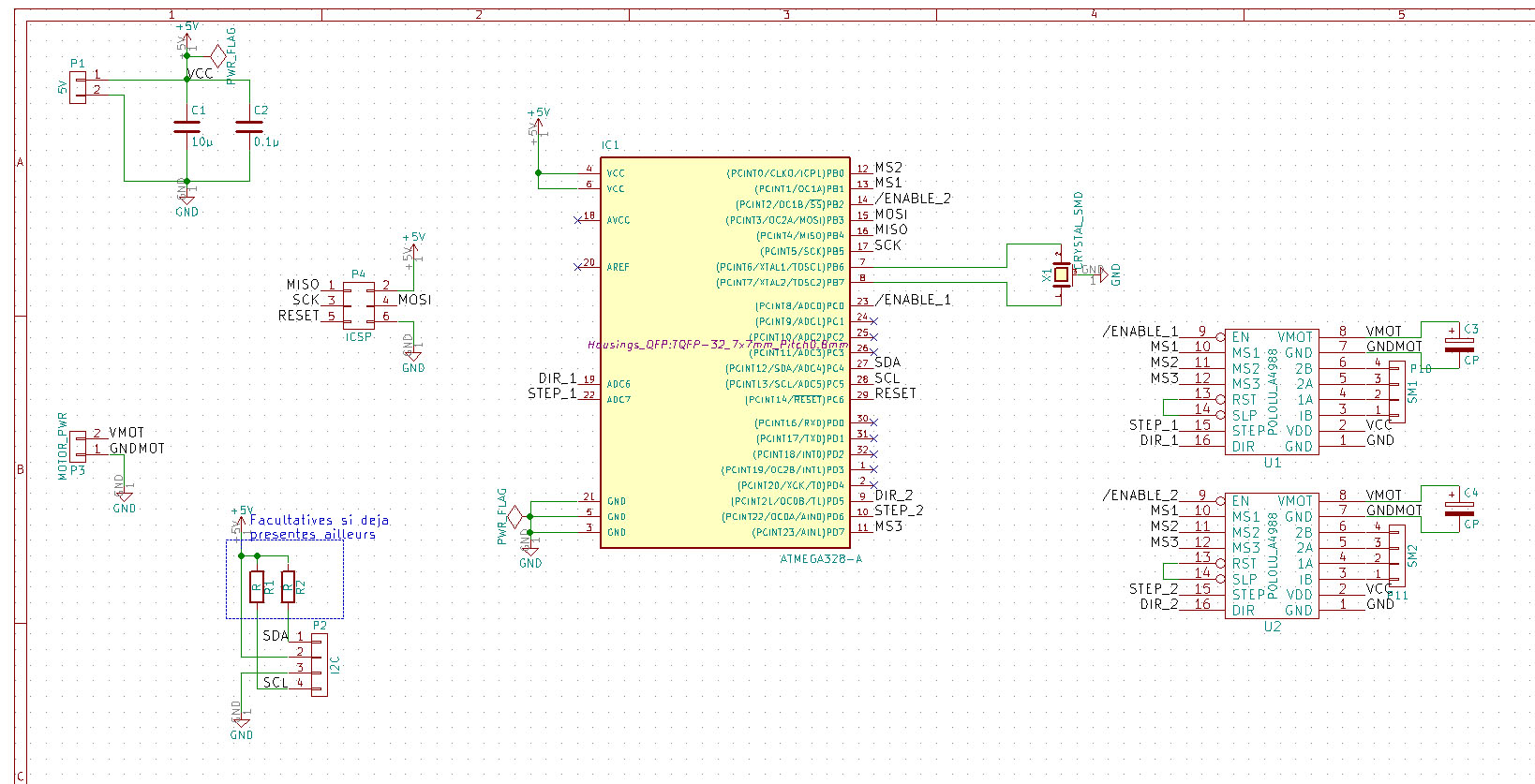
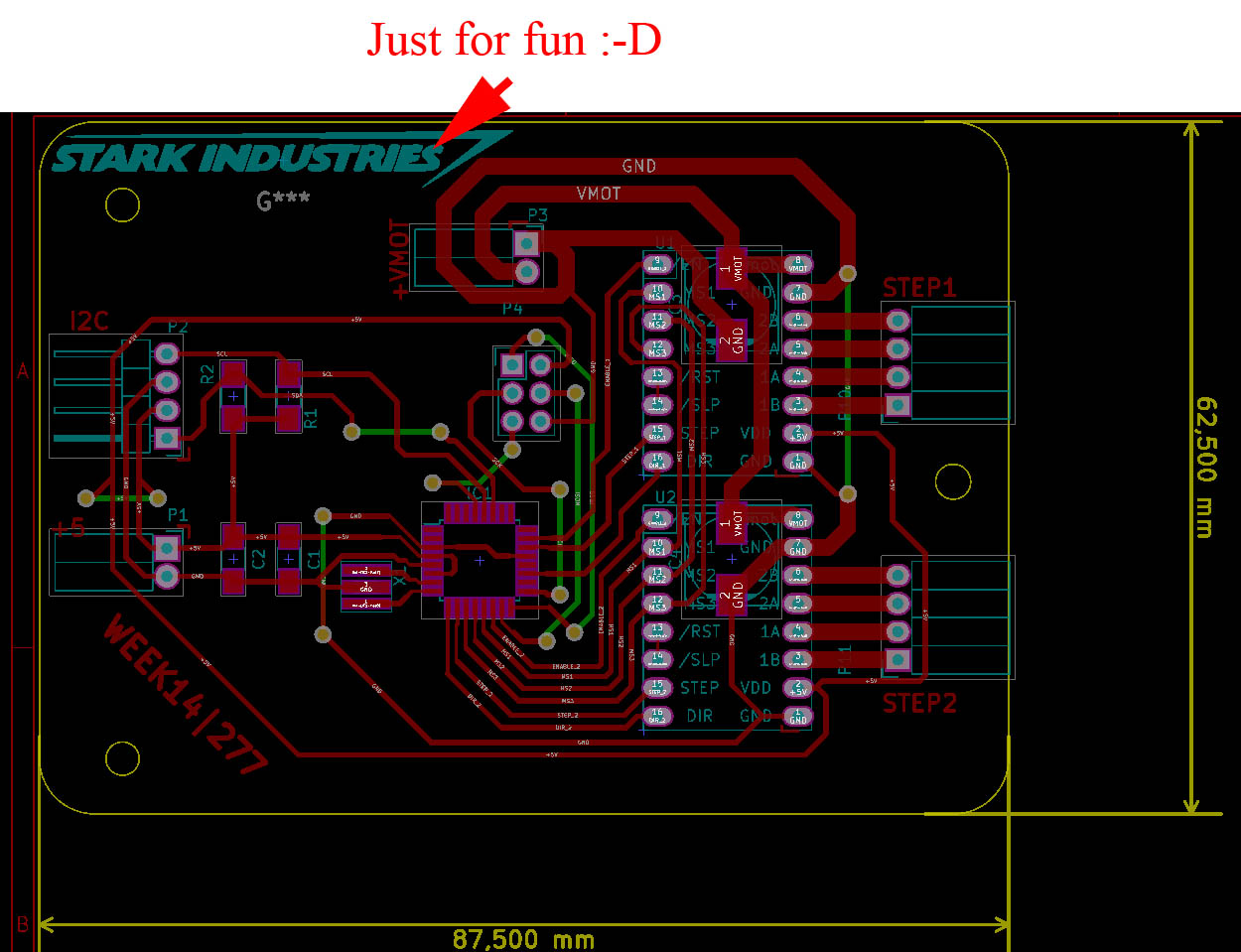
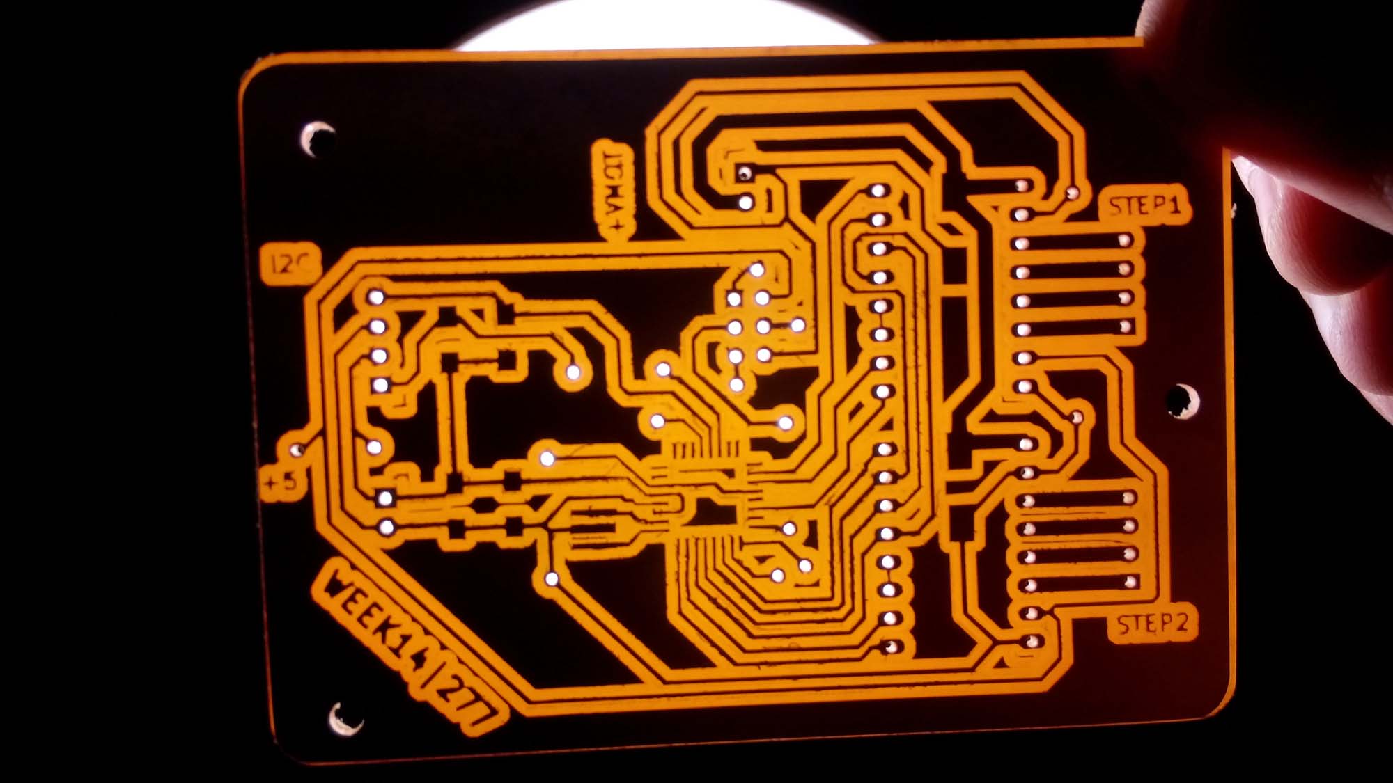
As always, I used KiCAD to do my schematics and PCB.
This time, I wanted to drill some holes because this should be my final board, so I prefer to have throuh-holes connectors for a better mechanical resistance.
First, I took care of using holes not smaller than 0,9mm because of the 1/32in (0,79mm) drill bit will be used for drilling as well as cutting the edges.
As always, I faced some problem with the thin pads of the TDFN32 package, it would not be a problem with another fabrication process, but with the milling machine it's very boring, because I already end up with some very thin pads, not really hard to solder but with a lot less mechanical resistance as I wish...
Drilling file
KiCAD can export a drill file, but it seems to be incompatible with fabmodules (yet)
So cheated.
I exported the SVG of the copper side and edge cuts (as always), and using Inkscape, I selected all the holes (by selecting one of them, and using "Edit -> Selection same... -> Fill color) as long as the border edge (as a reference)
I then pasted them in a new file, turning the white fill color black and saved as a png.
Please note : the border edge of both the traces file AND the drill file MUST be exactly the same. It is used as reference for positioning the holes, a slightly thi[ck|nn]er border will induce an offset in the holes position. I know, I made this mistake... (Fortunately, it was on an already wasted board due to another mistake :-)
Milling the board
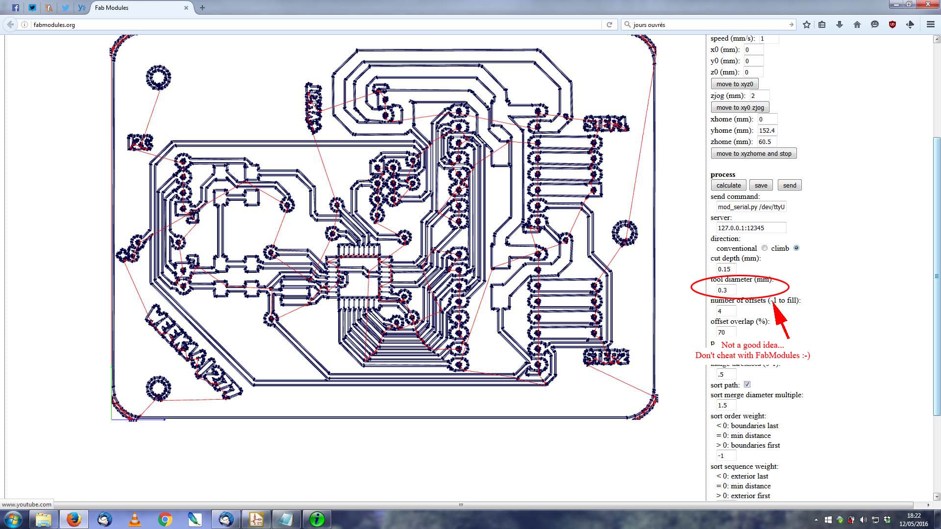
So, for the first try, I had two files - a PNG for the traces and a PNG for the drills and edges cuts. Unfortunately, the second one had a larger border because of fabmodules didn't do anything if border is < tool diameter. This obviously was the reason for one of the mistake above.
So I redraw the design with thicker traces AND modified the TQFN32 package footprint in KiCAD, making his pads thinner (-0.1mm each) (I saved it in a library for later use) witch was enough for the DRC in KiCAD to not complain about collisions while keeping a clearance of at least 0.4mm.
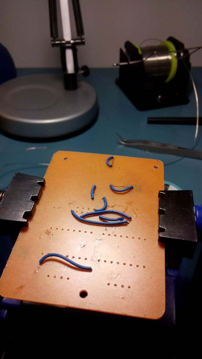
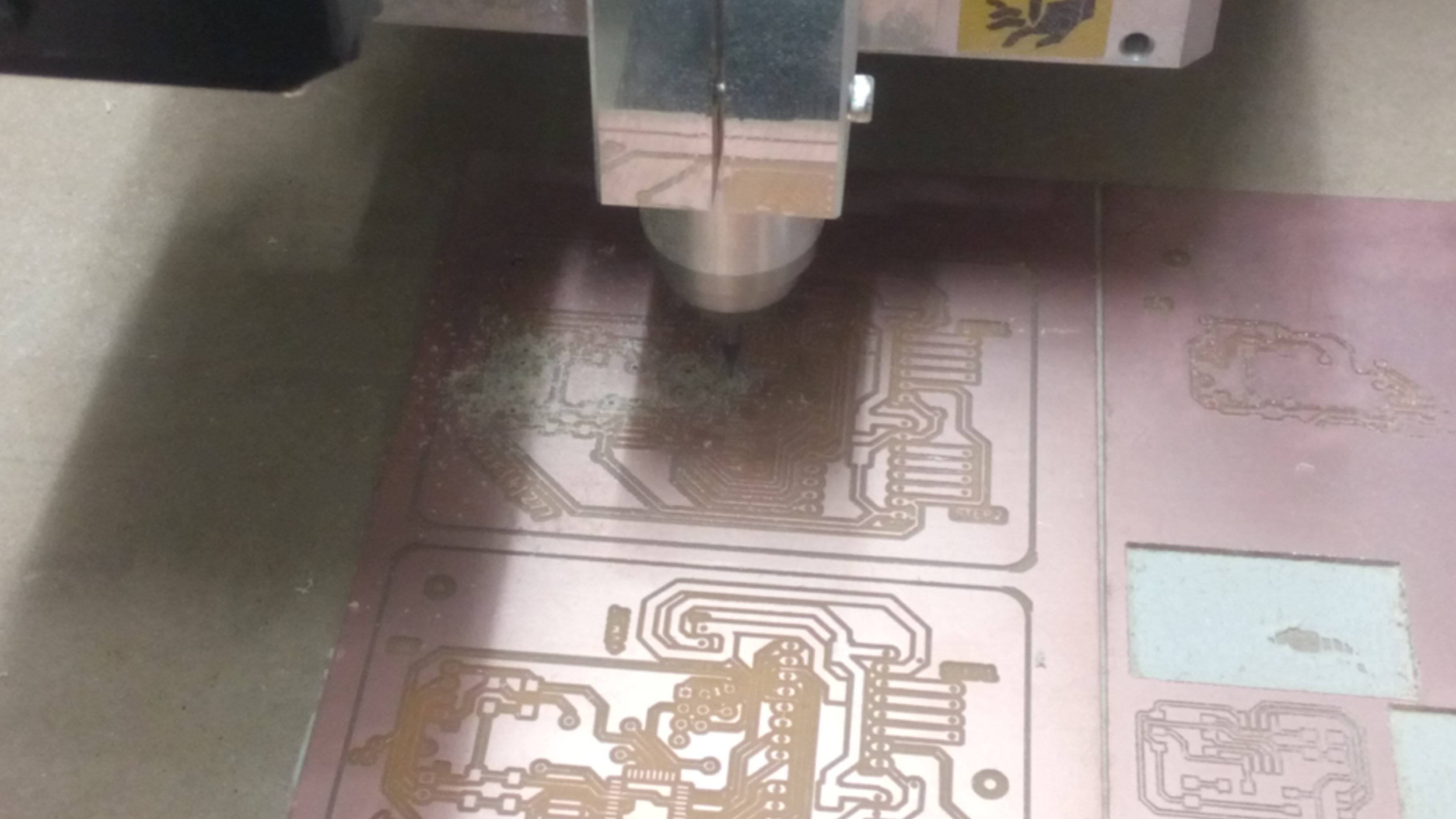 As you may see, the bottom board is the first try, the traces are way too thin (some of them just popped off the board).
I also had some trouble with the endmill, for the first board, the endmill was new and the cut are very clean. but for the second board, it seems that the endmill had already been used and the traces went dirty and hairy...
Drilling
As the first try went bad, I didn't cut neither the edges nor the holes, but I did a test to see if all would be OK for the next try. It appears that there was a little offset so, for the following try, I ended up doing this slightly differently.
First, I exported the three files (traces, holes and borders) instead of only two (traces and holes+borders)
Then, after the traces was milled and OK, I imported the two files in the vPanel queue (taking care that the holes file is the first) and voilà ! All the drilling/cutting went perfectly fine, the holes are perfectly lined with their pad. Success (even if some pads diameter are a bit too small).
Soldering
Well, do I really need to add some more comment here ? It's only soldering after all. The only thing I did is to tin all the traces (using flux and solder)
All I need to say is that, as I decided to drill holes this weeks, I could put some wire BEHIND the board, witch makes the things a bit less messy
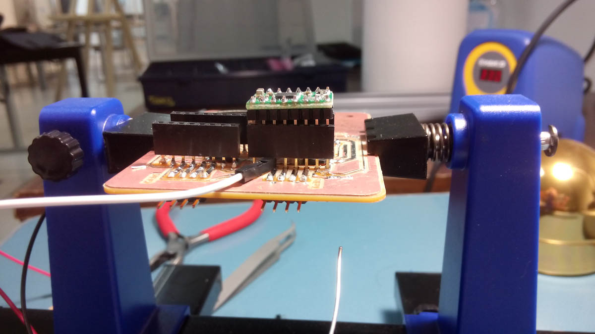
Oh, one more thing.
To solder the two pin headers witch will support the pololu stepper drivers, I used a little jig as you can see. So the headers are perfectly lined and at the same height.
Testing the board
As soon as the components was soldered, I fired up the power supply, the FabISP and go !
gege@ultron:~$ avrdude -c usbtiny -p m328p -U lfuse:w:0xfe:m -U hfuse:w:0xd9:m -U efuse:w:0xff:m

avrdude: AVR device initialized and ready to accept instructions

Reading | ################################################## | 100% 0.01s

avrdude: Device signature = 0x1e950f
avrdude: reading input file "0xfe"
avrdude: writing lfuse (1 bytes):

Writing | ################################################## | 100% 0.01s

avrdude: 1 bytes of lfuse written
avrdude: verifying lfuse memory against 0xfe:
avrdude: load data lfuse data from input file 0xfe:
avrdude: input file 0xfe contains 1 bytes
avrdude: reading on-chip lfuse data:

Reading | ################################################## | 100% 0.00s

avrdude: verifying ...
avrdude: 1 bytes of lfuse verified
avrdude: reading input file "0xd9"
avrdude: writing hfuse (1 bytes):

Writing | ################################################## | 100% 0.00s

avrdude: 1 bytes of hfuse written
avrdude: verifying hfuse memory against 0xd9:
avrdude: load data hfuse data from input file 0xd9:
avrdude: input file 0xd9 contains 1 bytes
avrdude: reading on-chip hfuse data:

Reading | ################################################## | 100% 0.00s

avrdude: verifying ...
avrdude: 1 bytes of hfuse verified
avrdude: reading input file "0xff"
avrdude: writing efuse (1 bytes):

Writing |                                                    | 0% 0.00s ***failed;  <=== That's not the first time... Don't know where is the problem ?
Writing | ################################################## | 100% 0.04s

avrdude: 1 bytes of efuse written
avrdude: verifying efuse memory against 0xff:
avrdude: load data efuse data from input file 0xff:
avrdude: input file 0xff contains 1 bytes
avrdude: reading on-chip efuse data:

Reading | ################################################## | 100% 0.00s

avrdude: verifying ...
avrdude: verification error, first mismatch at byte 0x0000                          <=== Idem, but the board works fine (but Brown out detection is disabled)
         0x07 != 0xff
avrdude: verification error; content mismatch

avrdude: safemode: efuse changed! Was ff, and is now 7
Would you like this fuse to be changed back? [y/n] n
avrdude: safemode: Fuses OK (E:FF, H:D9, L:FE)

avrdude done.  Thank you.

gege@ultron:~$ avrdude -c usbtiny -p m328p

avrdude: AVR device initialized and ready to accept instructions

Reading | ################################################## | 100% 0.01s

avrdude: Device signature = 0x1e950f

avrdude: safemode: Fuses OK (E:07, H:D9, L:FE)

avrdude done.  Thank you.
Programming
As for the week 13, I decided to program the board using arduino IDE because I lack time to focus on how to make the I²C bus to work using strictly MCU registers. I will do this as soon as time would not be a problem. I will also use what I had done for the output module.
The other reason is that I failed to make arduino-core and arduino-mk to work on my Debian :(
My goal
Basically, I plan to use a C Structure containing all the needed variables to control the motors of my telescope.
The first variable is a CHAR representing the command type (set speed, set acceleration, move motors, set microstepping...)
Other variables would be :
- (int) Speed,
- (int) Acceleration,
- (long) Distance,
- (char) Microsteps
- May be more later...
This method has pros and cons. The structure has an already known size, variables would be sent neverthless they are needed or not (they would be ignored by the slave). This could be compared to a REST API : all values are sent, everytime.
But as they will always be sent, even if not necessary, this induce an overhead.
I choose this method because it's easier and faster to implement, and given the fact that the motor board should not be flooded by a lot of commands frames, the overhead should not be a problem.
I created a document resuming the commands, types, and values for the I²C frame that you can see here. Obviously, it still in pre-alpha stage :-)
The communication is working, but it still needs a lot of work to be complete
The video above show a dimmed LED slowly pulsing (in place of a stepper motor - lab power supply wasn't available at this time).
For testing purposes, I send on the serial line of the Arduino some debug informations, here they are :
I2C Frame : 12
CMD_CODE : 16 0x10 Size : 1
MOTOR : 2 0x2 Size : 1
SPEED : 1500 0x5DC Size : 2
ACCEL : 300 0x12C Size : 2
Distance : 5000 0x1388 Size : 4
Microsteps : 1 0x1 Size : 1
Direction : 1 0x1 Size : 1

 0x10    0x2     0xDC    0x5     0x2C    0x1     0x88    0x13    0x0     0x0     0x1     0x1
Long dist check = 5000
Long dist check (hex) = 1388
Speed check = 1500
Speed check (hex) = 5DC
Accel check = 300
Accel check (hex) = 12C
For each field of the structure, it shows the decimal value, the HEX value and the size.
Then, it shows all the byte contained in the byte array
And finally, it shows some check to see if the byte are correctly re-ordered into their initial type (i.e. : Distance is an unsigned long (uint32_t)), as the I²C bus only support sending byte values, they need to be splitted while sending and re-appended when received. I got a lot of troubles doing this properly but I finally got it working fine.
The next day, after having fixed my crap, I finally had access to the power supply so I tested with real steppers (two different steppers for now).
It works as intended, even if the little motor is noisy.
The master code send random number of steps for the two motors every 5 seconds, thats why the shafts turns left, right, for different time, etc...
My mistakes
The first one was about the milling of the first board. As mentioned above, I cheated with fabmodules because the distance between the Atmega's pads was too small. This leave me with a board with half of the traces ripped off.
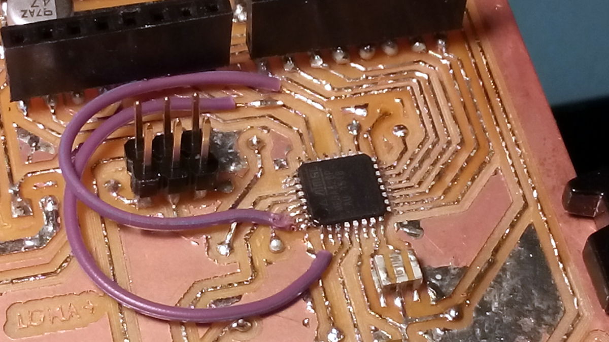
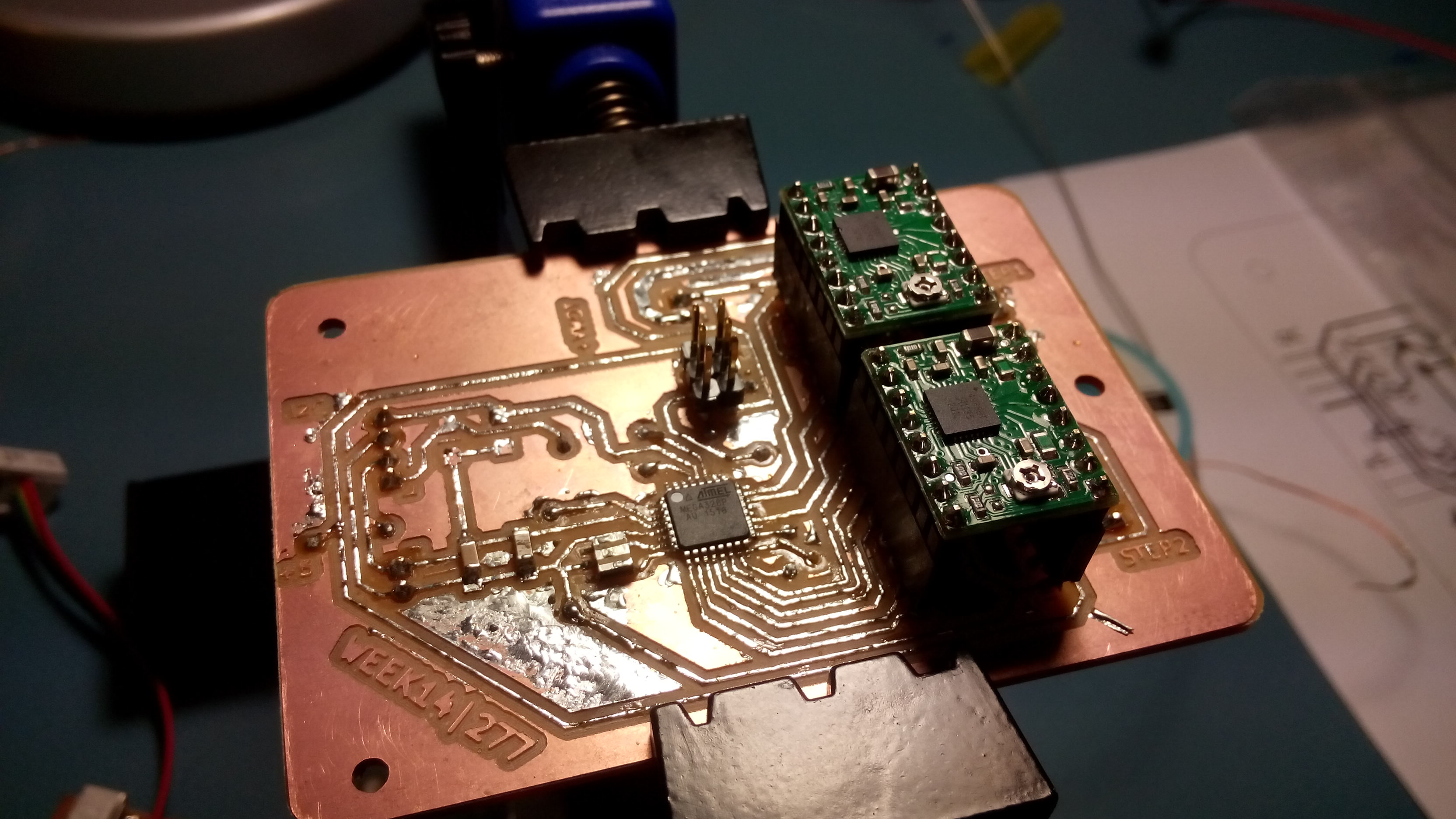
The second is a dumb one (again) : I used the ADC6 and ADC7 pin to drive the Step and Dir pin of my stepper driver. Seems fair, but ADC6/7 are input only... Crap.
So right now, my dual motor board only have one motor virtually working because of that.
I solved this "deadbug style", by soldering two tiny wires on two other pins of the Atmega. Making another board was also an option, but lack of time.
I could have cut the old traces, but this wasn't necessary
The other mistakes was more about trials and error when coding, there are a lot of them, most of them are dumb errors, impossible to describe without some gigabytes of storage in the FabAcademy repo.
One of the mistake about the coding was the splitting and joining of the not-byte variables.
I used left shifting on the received byte, but on my first trys, I inverted the order of the bytes, begining with the last instead of the first.
I had also some problems with type cast, using signed variable is problematic when shifting bits, so my final structure only contain unsigned char/int/long to solve this problem.
It's certainly not the best way to achieve that, but it works.