Playing with Sensors, PCB with photoresistor and LED
HOW TO: Schematic Design
- Create a Project and schematic canvas in Eagle.
- Include all the libraries in Eagle using 'use Library' from upper panel.
- Add the necessary components to the board.
List of components for the circuit is as follows:- ATtiny44 chip, find from 'atmel-new' > 'ATTINY44-SO14'
- 1 capacitor, 'C1206' > 'C-EUC1206 (C-EU)'
- 3 resistors, 'R1206' > 'R-EU_R1206 (R-EU_)'
- 2x3 PINHEADER, 'PINHD 2x3' > 2x3
- LED, from 'CHIPLED_1206' > 'LEDCHIPLED_1206 (LED)'
- Photo-transistor
- Include separate library
- Find 'PLCC2' >'SFH320'
- 1x3 PINHEADER for rotary motor, 'PINHD 1x3'
- Build the basic circuit
- Add components for input & output devices to a circuit


Board Design
- Create .brd file from the schematic
- Route the board, tools for routing can be found from the left panel of the screen.('Route'or AutoRoute')
- Be sure to adjust line width to 0.024(from 0.016 as default).
- In case of autorouting, you can adjust width of entire routing line in Edit > NetClasses.
- Create outline
- Select Line tool from left panel.
- Select layer as '20 Demension'from panel above.


.png)


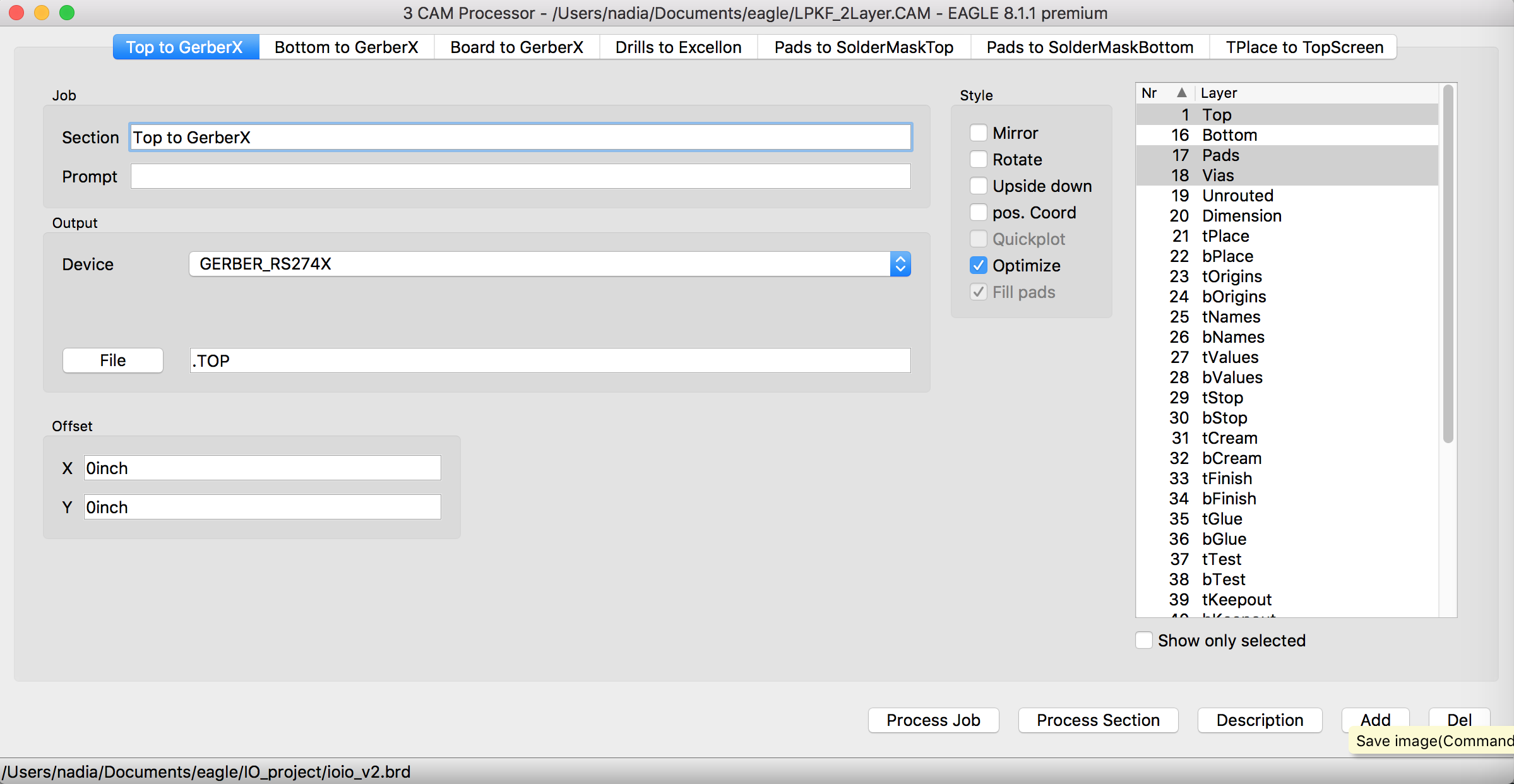
Create Gerber Files from brd and schematic
- Open CamProcessor
- Open Cam file from 'Open' > 'Job'
- select 'LPKF_2Layer.CAM' file.
- Change Device into 'GERBER_RS274X'
- In Drills to Excellon Tap, change Device into Excellon24 and Check whether the right .DRD file is included.
- Hit 'Process Job' button
- You will be able to see '.TOP',',BOT','.DRD','.BOA' files created in the folder where your board and schematic files are placed.


HOW TO: Milling
Our LPKF Milling machines make the PCB board in following orders. For each steps we just need to press the button telling it to prepare proper tools and do the work.
- How milling machine is working (so it just needed 3 buttons from the 'BoradMaster'
software)
- Make drills
- Draw circuit & Scrap other parts out
- Cut the outline


HOW TO: Soldering
After milling, I moved to soldering station, and soldered the small parts- Attiny44(It was really small as the name tells you explicitly), and even smaller parts(capacitor, resistors, photoresistor, led) to the PCB. Other than getting used to the concept of 'how soldering works' with your hands, things to consider in this part was getting right direction to capacitor(the arrow direction goes to the GND), and chips(you can find small dot from the bottom of the chip, and will be required to match it with your schematic). Also, including resistor value in your schematic might have helped me a lot, (and bother our instructor less :-)).


Programming Arduino as ISP
Here I followed steps described in here(Arduino as ISP)
and here(Attiny)
And you can find datasheet for Attiny chips(24/44/84) from here
- Program Arduino as a ISP(Upload Arduino as ISP)
- open file from 'File'>'Examples'>'11.ArduinoISP'>'ArduinoISP'.
- here you just connect Arduino to your computer (no other connection to your PCB board is necessary)

Programming ATtiny44
- Write a program for ATtiny44
- Connect PCB to Arduino - VCC, GNC, SCK, MOSI, MISO, RST needs to be connected to each others
& don't forget about connecting'capacitor' to Arduino board. (short leg with minus sign goes to GND, and the other to RST). - Upload program to PCB through Arduino.
   int var = 0;
   int thres = 160;

   // the-setup function runs once when you press reset or power the board
   void setup() {
     // initialize digital pin LED_BUILTIN as an output.
     pinMode(3, OUTPUT); //led
     pinMode(2, INPUT_PULLUP); //photo-resistor
   }

   // the loop function runs over and over again forever
    void loop() {

       //digitalWrite(7, HIGH);
       var = analogRead(2)/2; //read of voltage
        if (var < thres){
           digitalWrite(7, HIGH);
        } else {
            digitalWrite(7,LOW);
        }
    }
For Programming, I made a little bit of change from a 'blink' example which is already provided in
Arduino by adding right pin number for led(according to a schematic). I also declared input pullup
for photoresistor.
In the loop, Attiny44 reads a value from the designated pin(photoresistor).
Photoresistor changes resistance based on
the light, hence creating the voltage drop.
Specifically, in the dark, the resistance is high(several megohms (MΩ)), when it gets brighter,
resistance gets low(only to few hundred ohms).
'AnalogRead' will give values between 0
~ 1023 mapped from GND(0V) and 5V.
Using a multimeter, we found a kind of 'border' of voltage value for photoResistor is 1.4V; which we
set globally as 'thres=160'.
Hence the code does following: When the light coming to a photoresistor is smaller than
'thres'(threshold), led will blink, otherwise not.


Below is result from the assignment..