Assignment:
A_ design and build a wired and/or wireless network connecting at least two processors.
A_ design the network
I will make the hellobus.45 asynchronous bus. I researched documentation of students from previous year who had done this same exercise for this assignment and found the one from Edgaar, a student from my fablab that made a straightforward documentation. I will use it to guide me through.
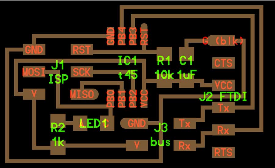
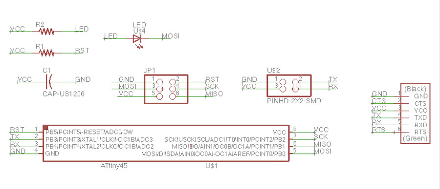
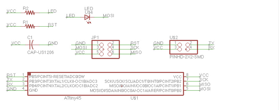
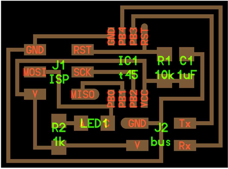
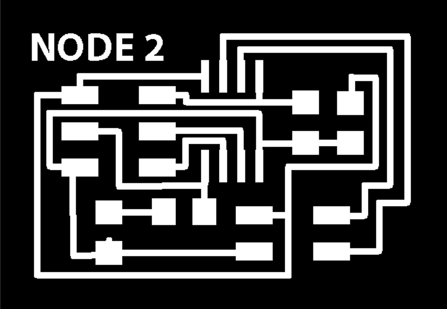
I started by designing the schematic and the boards with eagle.
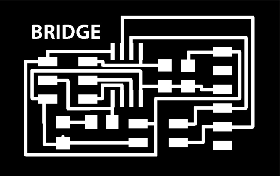

The milling machine were collapsed on thursday in my lab and so I could only manage to mill the bridge and had to wait for the day after so I decided to pair with my colleage Trini who was in the same situation and who had managed to mill her 2 nodes but not her bridge.
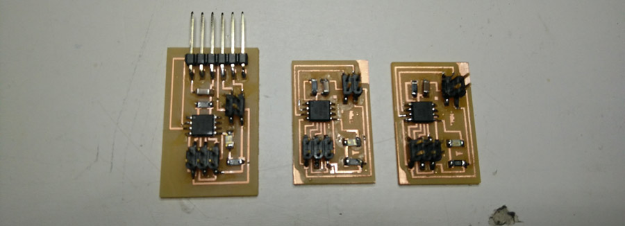
The bridge programmed correctly at the first attempt and apprently the node did also. But the day after when I wanted to document the process i could no longer make the led blinks nor reprogram the nodes. Terminal would never complete compilation.
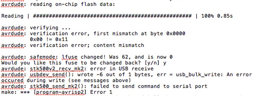
I tried and tried it again, and strangely enough at some point I managed to program both nodes but when I connected them to the bridge and send the serial monitor it would not respond accordingly. Also the led would lit on and off without apparent reason.
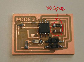
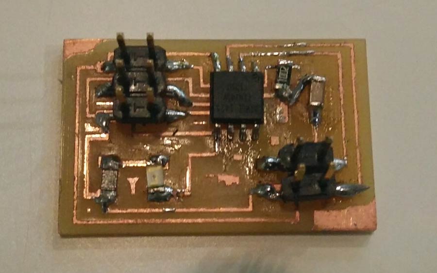
So I decided to go back to the board, reveiew soldering and tried again but still got erratic response. So I checked the reference boards and realized there were errors in the board design of the Nodes: the 1UFcapacitator and the 10k resistor were not properly wired. So I just fixed it so I could carry on with the programming.
1-Programming the bridge board
The programming is a step by step process. The bridge and each nodes need to be programmed seperately.
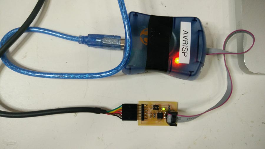
A- program the bridge board by conecting the FTDI cable (give power to the board) and the programmer (in my case avrisp2) to the 6 pin hearder.
B- open the .c file and locate the code line: #define mode_id '0' ( the 0 is the tag identifying the bridge board - it could be whatever you decide)

C- go to terminal, to the directory where the .make file is stored and type:
make -f hello.bus.45.make program-avrisp2
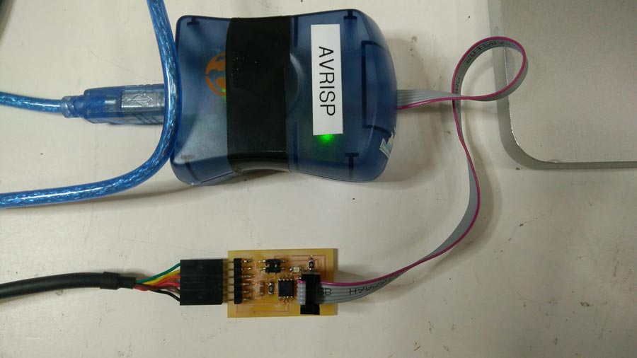
The led on the node board should light, the Avrisp light turn orange (while programming) and turn green again when programming is completed. Terminal should compile (no error message) and led remained off after completion.
1-Programming the nodes
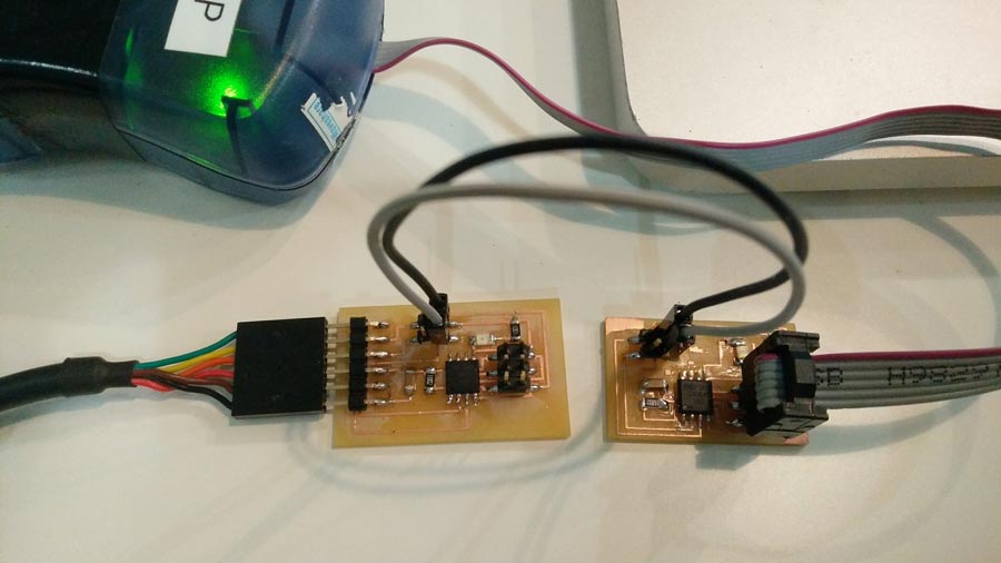
A- program the 1º node by conecting the programmer (in my case avrisp2) to the 6 pin header and providing power to the node (by connecting the VCC and GND of the 4 pin headers respectively to the VCC and GND of the node node.
NOTE: Power can be provided to the NODE also simply by connecting VCC and GND from an Arduino or even through the ftdi cable.
B- open the .c file and locate the code line: #define mode_id '0' and change the 0 for a 1 ( or whatever you feel like but needs to be different from the bridge).

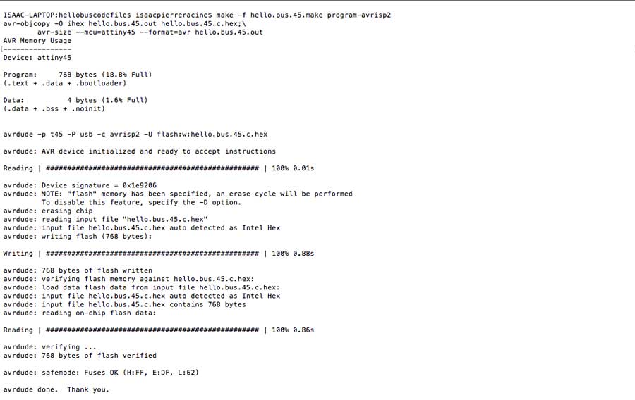
C-go to terminal, to the directory where the .make file is stored and type:
make -f hello.bus.45.make program-avrisp2
The led on the node board should light up, the Avrisp light will turn orange (while programming) and turn back to green when programming is completed. Terminal should compile (no error message) and led of the node turn off after completion.
Program the 2º node repeating the same operation done for node 1. MAKE SHURE YOU EDIT THE I.D OF THE NODE IN THE .C CODE. Otherwise 2 nodes will have the same ID and won't blink according to the program.
To verify the boards are programmed and work properly:
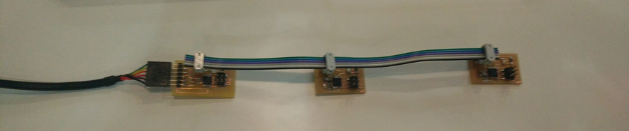
connect the bridge to the FTDI cable + connect the node in series to the bridge using the 4 pin header (GND, VCC, TX and RX pins)
-open ARDUINO IDE (no sketch needed)
-open the SERIAL MONITOR window.
-write 2 in the serial window and press SEND.
-Arduino compiles the code and shows the program in the serial window, and simultaneously the lights on the boards will blink.
The blinking sequence go like that: bridge and node flash at the same time and the node corresponding to the number entered in the serial window blinks once more.
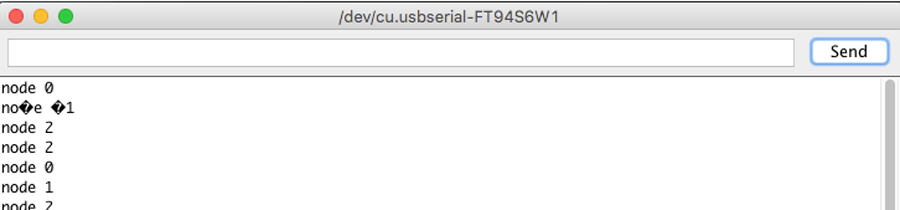
Note: I looked into the meaning of those "question mark" characters that appeared in the serial monitor window and I figured it must be due to a mismatching between transmitter and receiver encoding. It is strange as there were no strange characters in the commands I sent. Apparently this happens only when not standard ASCII characters are sent.
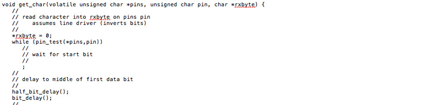
Here the video of the complete sequence HERE.
Milling and soldering is usual business by now. I lost lots of time troubleshooting the nodes and that took time that I had planned to invest into the programming part. Anyhow there is something that I found strange and I looked into it. During the .c and python workshop we had a few weeks ago, our instructors emphasized the fact that in serial communication the TX and RX pins are always crossed between 2 connected nodes. But the boards (bridge and nodes) are serial bus and connects TX with RX in a linear way (not crossed). I researched and figured that this crossing do not necessarly have to happen through hardware. It can be programmed in software. Analysing Neil's .C code I identified the lines that makes this function.