This week we are focusing on Computer aided design. The officiall lecture notes are found here.
A video of the lecture itself can be seen here.
Goals
From the lecture page
Model (raster, vector, 2D, 3D, render, animate, simulate, ...) a possible final project, and post it on your class page
Extra goal from my instructor (Ohad)
Model the final project in many differnt ways, use software you are unfammiliar with and test something parametric for the coming weeks lasercutting assignment.
Summary and index:
2D:
I used Inkscape for drawing my project in 2D and found it quite nice to work in and it had some interesting properties like the ability to "hack" the raw XML in the .svg file (that is the format inkscape saves its files in).
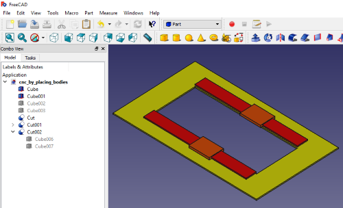
I first tried Freecad but found it too limiting since you can't make multi body parts or assemble parts to form larger constructions. I inted to make a CNC machine for my final project and will have many different parts that I'll model separately, therefore I need a program that can handle assemblies of parts in a structured way.
Then I tried modeling in Rhino which I liked better. It differs from how I usually work in industrial CAD programs like Solidworks and Inventor but I look forward to getting better at its more flexible design approacch. I think it will be particularly useful for "sketching" in 3D. I also started to explore grashopper, which is a parametric visual programming environment for Rhino.
I also explored some features of Fusion 360 that I had not previously tried.
Specifically the motion study and collaboration. I looked very promising and was fairy easy to learn.
The work week started out a bit chaotic with me trying to decide what my project actually is. Or rather where to draw the line.
My thoughts:
Do I make a single axis CNC machine and make it modular, like the ones used in Machines that make" project? link or do I go for the full CNC mill, with a closed loop spindle? If so, will I then make all five motor controllers or just the stepper drivers etc...
Decided:
Will make robust CNC with minimum of vitamins. (Motors and microelectronics)
I will use the input devices week asignment to build an RPM meter for milling spindles.
(Long version written up in the DIY CNC project.
My first attempt at drawing final project in inkscape: Original SVG file
Method and progress:
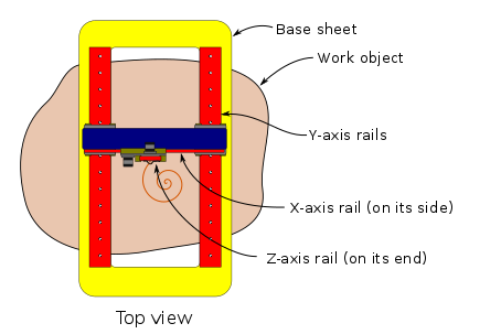
I sketched first on paper and then in inkscape. It shows the CNC drawing on a large irregular work object with a pen.
I particullary liked experimenting with the "align and distribute" tools.
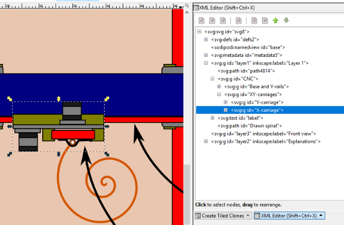
I also tested out the XML editing feature. I am not sure how to make good use of it yet but I bet it will come in handy.
I named all my groups (logical sub-assemblies) to play with it a bit.
XML in Inkscape and naming groups:
Experiments with XML and SVG files:
I decided to run a test: Can i display the SVG here on my wepage, as a vector image? Original SVG file link
Apparently!
Question:
Since it is vectors, can I animate it?
I googled it and it seems like it! I found a couple of "how-tos":how-tohow to2
Test: Does it work? Original SVG file link
SOMETHING HAPPENED! my X-carriage is somewhere else! This needs to be tested!
I read some more how-tos and made this happen to the same file Original SVG file link
After some trial and error I found out that I had a transform action in my file that had moved my coordinate system.
After I compensated by just copying in the offset (it is the 71.4 below) I managed to animante the individual axis.
This made me reseach some more and I found a loop strategy here link. I added it as well Original SVG file link Original SVG file link
Then I tried nesting the two moves and voila! It worked! Original SVG file link
Here is the code for the looping X-carrige as example:
<g id="X-carriage" transform="translate(0.5291667,71.437539)"> <!-- This is the inkscape group named "X-carriage" -->
        <!--- Start tranformation of axis -->
        <animateTransform
                    id="anim1"
                    attributeName="transform"
                    attributeType="XML"
                    type="translate"
                    from="0 71.4"
                    to="10 71.4"
                    begin="0s; anim2.end"
                    dur="2s"
                    fill="freeze"/>
        <animateTransform
                    id="anim2"
                    attributeName="transform"
                    attributeType="XML"
                    type="translate"
                    from="10 71.4"
                    to="0 71.4"
                    begin="anim1.end"
                    dur="2s"
                    fill="freeze"/>
      <!-- end transformation-->
I made an Inkscape template for the most common transformations. Download it (Right click, save file as...) and open it in Inkscape to play with the values or copy them into your own files.
It seems like this does not work in the Microsoft Edge browser, probably not in the older Internet explorers as well. Works fine in Google Chrome!
Prior experience: Little, a few hours.
Downloaded the software.
Read through the Getting started guide
Read thorugh the sketcher workbench best practices in the program.
I'll attempt to reuse the same colors that I used in Inkscape for the 3D models.
Drawing my project in 3D
First attepmt, I used the part workbech since the Assembly workbench isn't released yet.
However this was horribly slow and unpractical. Will experiment with drawing it as a big body instead.
Question, do everything as a mega sketch and extrude parts from or do step by step sketches to preserve individes like that?
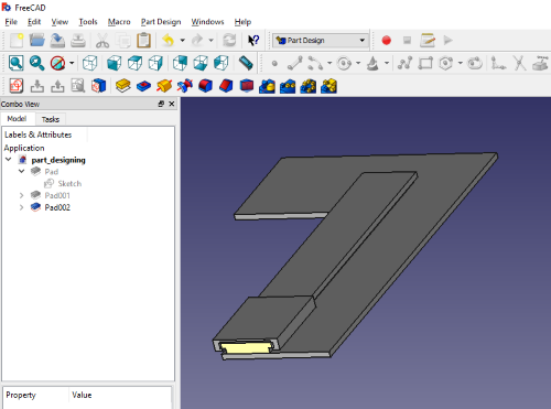
Did it sketch by sketch since it turns out it does not allow for sketch reuse.
This is as far as I got, it bugged when I tried to mirror out the part. I choose not to solve it since I don't see me designing new designs in
freecad when there are better options.
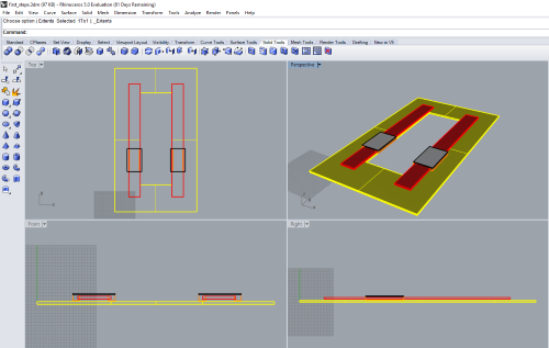
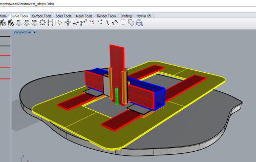
Rhino
Previous experience. None. But I have used ligthwave in the 90ies.
This was so much better! At least I get somewere!
Success! Din't have time to make the tape and animation before the weekend.
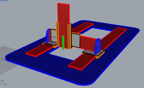
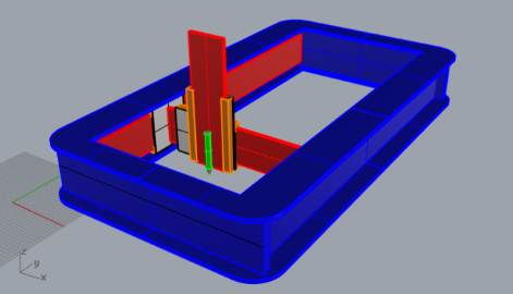
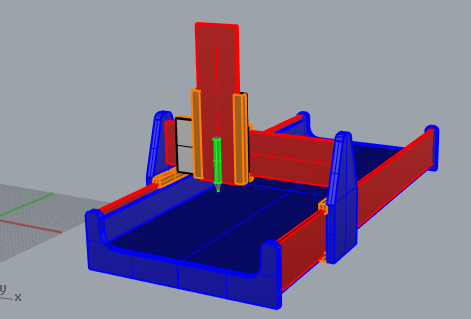
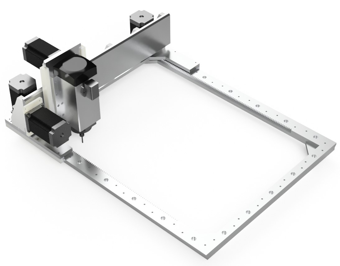
Made three different CNC machine configurations in Rhino Original Rhino 3dm file Original Rhino 3dm file Original Rhino 3dm file
UPDATE:
For reference, this is my final design drawn in Fusion 360 for my final project (Those files are on the final project site.)
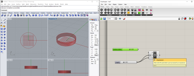
Parametric Rhino - Grashopper
I tried out grashopper, the parametric visual programming enviroment for rhino.
I used this "Hello world!" instruction: Youtube link Original 3dm Rhino grashopper file
Looking forward to playing more with this, I have not programmed visually before!
Tested the rack and pinion generator from fellesverkstedet git link
Feedback:
Gear for pinion maker is impossible to use without a pinion. Can this be hidden from the menu or marked as "Use Roller rack and pinion maker instead"
Pinion tooth spacing factor. Possibly remake to pinion tooth spacing, I can look into the math.
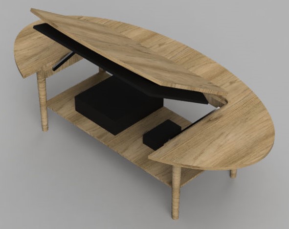
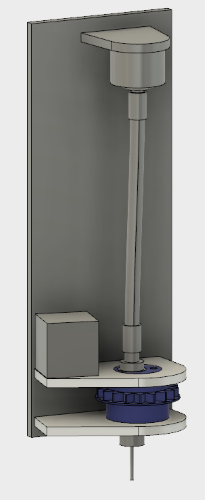
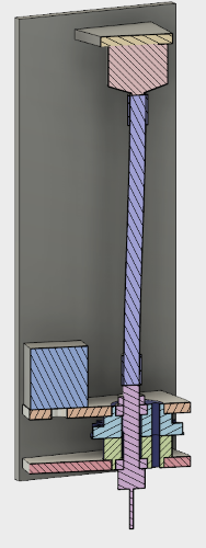
Designed a concept for an occilating milling spindle. Fusion Cloud link
Learned about the version handling system in Fusion360 by playing around with it. It matches the git-version handling terminology with master-branch etc.
I used it to start a collaboratory project with Jens Dyvik. Original f3d fusion 360 file


 Original SVG file link