add an output device to a microcontroller board you've designed and program it to do something
Idea
I'll make my own version of the satstep6600, which is a stepper driver. A stepper driver is required to operate and control the position of stepper motors. My final project is a DIY CNC and it will use four stepper drivers.
Therefore concider all content on this page to be licensed Attribution-NonCommercial-ShareAlike 4.0 International (CC BY-NC-SA 4.0).
Hopefully I can get the satshakit team to remove/clarify the non-commercial requirement. If so I will upload my work to fellesverkstedet/fabricatable-machines, look for it there if you need a more free license.
Side by side comparison with original
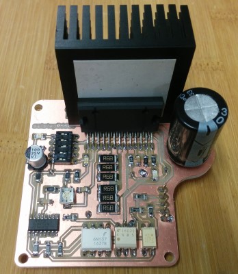
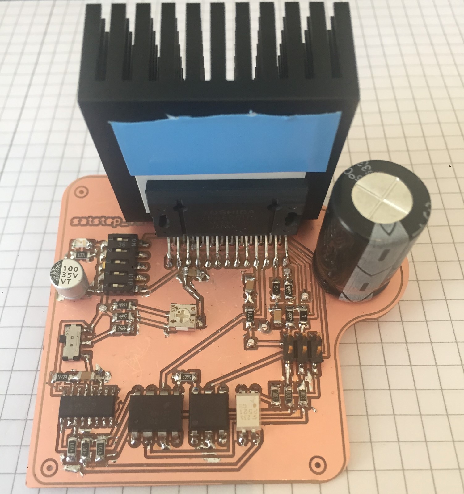
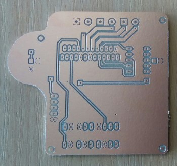
Original Satstepper
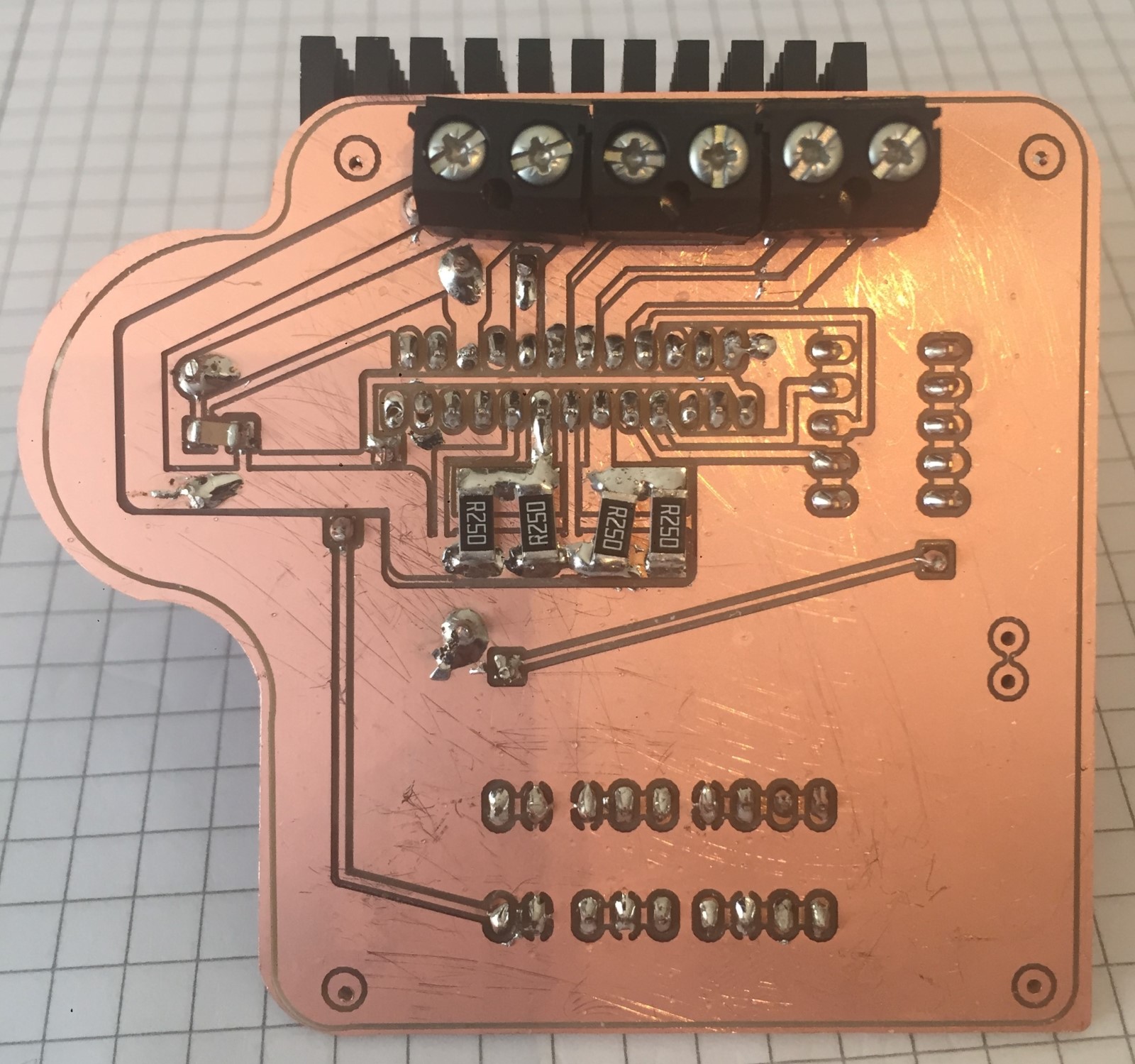
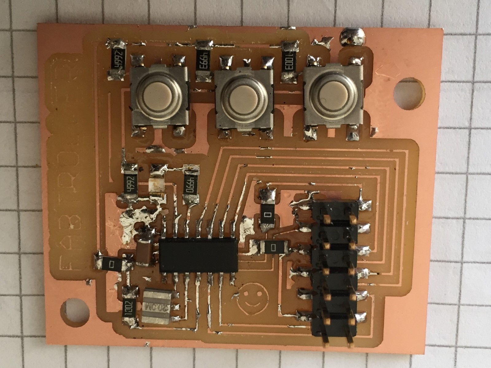
My version 2.0
Original features
Always drops holding torque when motor is stationary
At max potentiometer settings the Voltage reference (Vref, controls the output current) greatly exceeds data sheet specifications
Current through MO and ALERT pins exceeds datasheet specifications to power LEDs
Dip switches are not in the same sequence as in the data sheet (not wrong, just complicated)
Uses non fab-inventory current sense resistors
Shared ground plane for motor currents and signals
My 2.0 features
Switch lets user choose if holding torque should be maintained or reduced
Voltage reference can not be made to exceed specifications
MO and ALERT gives a digital signal and current is kept inside datasheet specifications
Dip switches are in the same sequence as in the data sheet (making setup easier)
Uses fab-inventory current sense resistors
Return ground for motor currents kept separate from signal ground plane.
Other notable updates:
Improved capacitor placement in accordance with the data sheet
Below is a video of me testing the stepper driver with a push button generating the clock pulse. It moves 1,8 deg per pulse (it is stet to 200 full steps per revolution) which is bearly visible.
UPDATE 2! I used that setup to test run my first machined linear axis for my final project
Here is a video of the first test
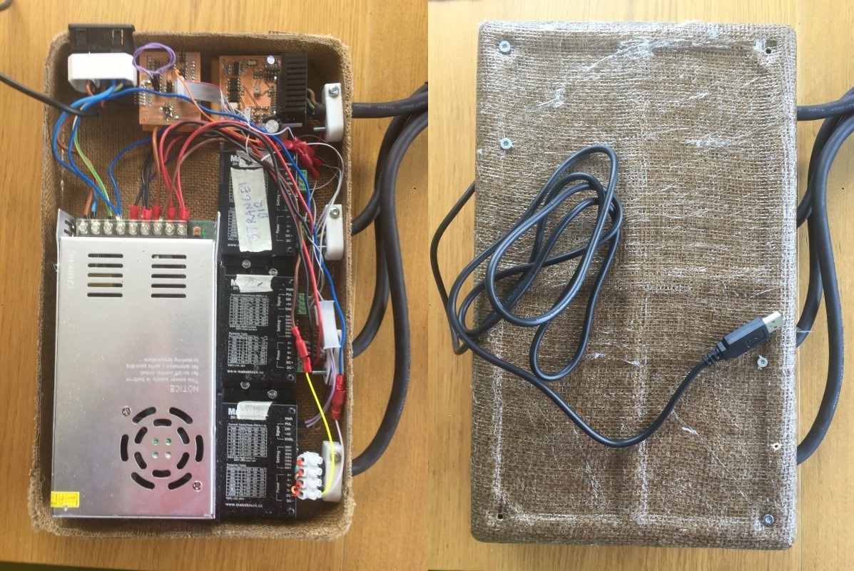
I later installed the driver in my final project. I didn't have time to make three more drives but I fully intend to do so after the end of fab academy. I'll also add some more improvements that I have thought of while using it.
Future improvements
Mount the IC paralell to the PCB instead of perpendicular. This is a significant redesign of the board but will make it much easier to handle and place. It will also reduce the risk that the heat sink touches the solder tips.
Investigate the Vref control. Possibly replace the potentiometer with another dip switch array to create distict steps. I'll start with a more thorough benchmarking of this method to see if reality matches theory. The 5V output from the IC is actually 4,8V and might be throwing off my calculations.
Replace the throught hole optocouplers with surface mount versions, possibly standardize to one type instead of three different ones.
Possibly make the motor connections with a connector plug instead of a screw terminal.
When googling the different components I found that several are discontinued or about to be. This is worth noting if we want to make this card in the future. (Check the optocouplers in particular.)
The Monostable multivibrator has another channel that isn't used. Perhaps there is another cheaper one channel component or can it pehaps be used to improve the incoming CLK signal pulse quality?
The MO_ALERT, 5V and GND output pins in the 3x2 header are superflous, I'll drop them in next generation.
Process
The all in one board idea
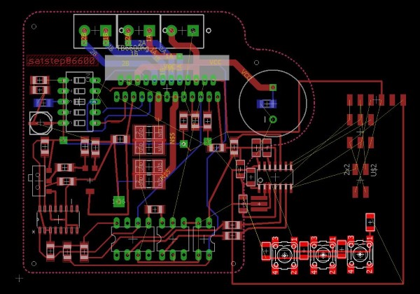
The Statstep6600 original stepper driver board did not have it's own programmable microcontroller. At first I wanted to add a attiny44 and some buttons so that I could drive it direcly. Creating a one card stepper driver, controller and input device. However while routing the board I noticed that it made the stepper driver card needlessly overcomplicated and would not make sence in the long run. Especially since I later wanted to make four of them that would serve one controller. So I changed my mind and broke it up into two cards that became my input and output device respectively.
Here is my (abandoned) All-In-One_board that I ended up breaking into two boards.
Datasheet:
Output monitor pins (ALERT): Maximum of IALERT = 1 mA
Output monitor pins (MO): Maximum of IMO = 1 mA
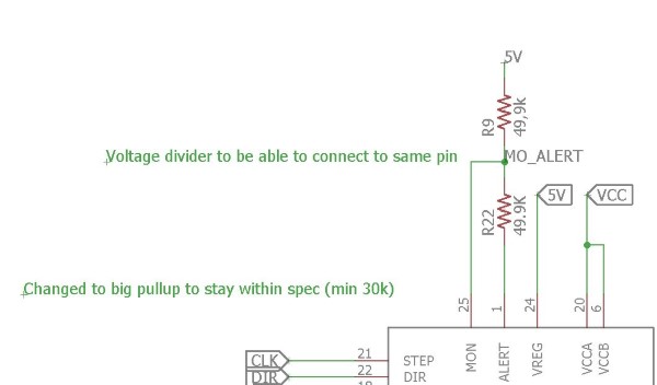
"As for the pull-up resistance for MO and ALERT pins, please select large resistance enough for the conducting
current so as not to exceed the standard value of 1 mA.
Please use the resistance of 30 kΩ or more in case of applying 5 V,"
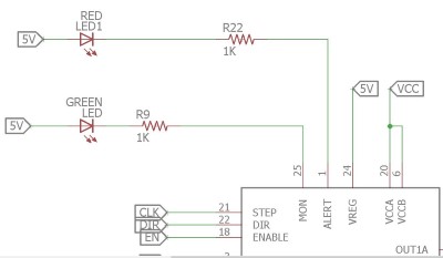
The MCL-S250GC LED is used in SatStep6600 (from the BOM).
I used this LED calculator to figure out that with that Green LED the required resitance is 3,3kOhm or the current will exceed the specs, however, that would make the LED 20 times darker, which I assume is invisible.
I contacted the originator of the card and discussed this. He agreed that this is a mistake in the original design. But he also told me that satstep6600 boards has been successfully made and worked with these values in place.
I wanted to respect the max values so for my board I choose to use 49,9kohm pull up resistors (they should be minimum 30kOhm according to the data sheet) and I connected them together so that I can use the combined digital signal to detect the full step pulses (MON) but also read an anlog voltage to check for overcurrent or thermal shutdown that triggers the ALERT pin, should I need it. UPDATE!: I built but ended up not using this feature, so far.
When not triggered the driver alert pins are in a tri-state condition, which means that they are not high or or low but rather acts as nothing is connected. This is often written as Z.
MON
Alert
Voltage at net point MO_ALERT
TRI-STATE
TRI-STATE
5V continously (HIGH)
LOW
TRI-STATE
0V in short pulses (LOW)
TRI-STATE
LOW
2,5V continiously (Can be read by AD converter)
LOW
LOW
0V Will not happen. MON is a pulse indicator and ALERT will stop pulses.
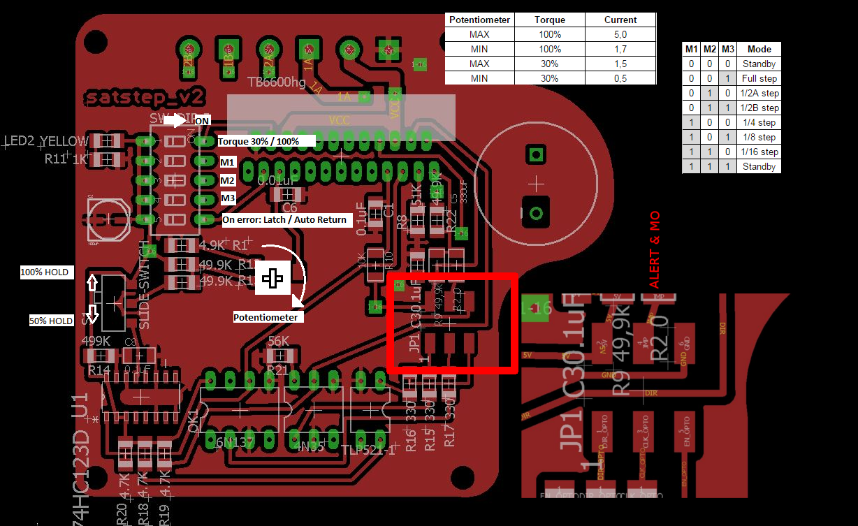
Potentiometer overloads the driver
The card is equipped with a potentiometer so that a user can set the desired current to send through the motor. You need this control since you would fry a small motor if you give it the full 4.5A that this driver can output. Also using a uncesserarily high current can cause the motor to vibrate more or genereate excessive heat which leads to other problems. The output current is controlled though a reference voltage Vref and "Sense resistors" which is used by the driver IC to measure the current through the motor coils. These resistors have a higher precision and power tolerance for this purpose.
I did the math on the original reistors that control the Vref depending on the setting on the potentiometer. The resulting voltage was way higher than specified in the data sheet for the driver IC. After some mailing with the originator and lots of head-scratching I found out that he had used a short version of the data sheet with a higher voltage threashold and that he had ment that you should use a 5k potentiometer rather that the 10k one that is in his schematic on github.
I wanted the potentiometer to allow the used to go from max to min current. To achieve this I found out I also needed to change the sense diodes (Rnf) since the output current is dependent on both them and the Vref according to this formula I found in the data sheet :
Io (100%) = (1/3 × Vref) ÷ RNF
I finally found resistor values that would work and that were available in the Fab-inventory.
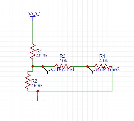
I used EasyEDA to verify my spreadsheet calculations for the resistors. My project file is here. After you have logged in you can simulate circuits by pressing the top right menu and choosing "Miscellaneous".
Screenshot of my EasyEDA schematic
Seeing it return the same values as predicted was very satisfying :)
Capacitor placement
Quoting Page 31 in the datasheet, the italic text is my comments
Note 1: Capacitors for the power supply lines should be connected as close to the IC as possible.
The small cap can be moved closer. The large cap is oversized (47uF rec is 330uF), better or worse?
Note 2: Current detecting resistances (RNFA and RNFB) should be connected as close to the IC as possible. They can be moved closer, but not much.
Note 3: Pay attention for wire layout of PCB not to allow GND line to have large common impedance.
The use of the bottom layer as a ground plane should limit these risks. I could add more vias to further reduce impedance.
Note 4: External capacitor connecting to Vreg should be 0.1μF. Pay attention for the wire between this
capacitor and Vreg terminal and the wire between this capacitor and SGND not to be influenced by
noise. This capacitor is on the very end of the longest trace on the board. Should be easy to improve lots.
Note 5: The IC may not operate normally when large common impedance is existed in GND line or the IC is
easily influenced by noise. For example, if the IC operates continuously for a long time under the
circumstance of large current and high voltage, the number of clock signals inputted to CLK
terminal and that of steps of output current waveform may not proportional. And so, the IC may not
operate normally. To avoid this malfunction, make sure to conduct Note.1 to Note.4 and evaluate
the IC enough before using the IC.
I made adjustments to the board layout according to my comments above and also broke out the ground return from the motors from the signal ground plane. They now meet only at the ground wire terminal.
Other updates I made
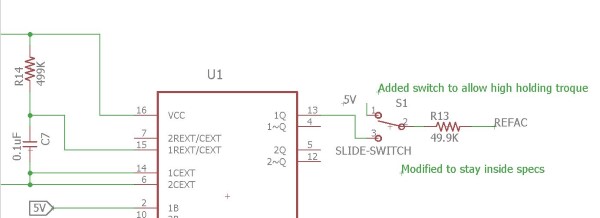
The circuit has a "Dual Monostable Multivibrator" (Component 74HC123D, data sheet) and its connection to the Vref gave me some pause. It took me quite a while to figure out. The purpose is to reduce the holding current when the motors are holding a position. A capacitor+resistor on the board functions as a timer and makes the driver deliver full current as long as the stepping frequency is higher than 20 hz (hz= steps per second). When it is slower Vref is reduced to about 50%. This precentage can be tuned by changing the other resistors in the circuit.
74HC123D Timing formula: (true for 5V and capacitors larger than 0.1uF)
twOUT = 1.0× CX× RX
There:
Length of pulse in seconds= 1 * 0.1uF * 499kOhm
0,0499 = 1 * (0,1*10^-6) * (499*10^3)
1/length of pulse = 20 hz
Since I needed to alter the resistors connected to this component anyway I also added a switch so the the holding torque can be fixed at 100%.
The switch mimics the behaviour of the multivibrator in its HIGH output state.
Outdated components and unexplained choices.
When googling the different components I found that several are discontinued or about to be. This is worth noting if we want to make this card in the future. (Check the optocouplers.)
Three different optocouplers are used, it feels like a three channel one could have worked, if such exist?
The Monostable multivibrator has another channel that isn't used.
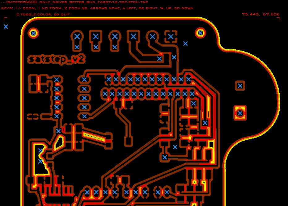
Fabbing the board
I used PCB GCODE in EAGLE to generate double sided milling, drill holes and the cut-out milling. This was my first attempt to get it working and I couldn't yet get it to do multi pass milling for wider insulation between traces.
PCD Gcode generates GCode that is directly compatible with the CNC machines in the Verket fab lab.
I really appreciate to be able to CAM directly in Eagle since it makes it really fast to do updates if you realise something is wrong when you stand by the machine. And it is also better at doing contour milling and drilling than Mods.
Trick for cutout milling:
Select "line" (not "Route")
Set it to be slightly wider than your cutout milling bit
Set it to layer "Milling"
Draw where you want to mill the outline.
In the PCB-Gcode plugin, first pane, under "Board" check "Generate milling" and set it to slightly deepther than your board is thick.
However sometimes it bugs when trying to generate multiple isolation milling passes, single pass always works.
If you get a bug, try this:
First delete any extra "ground plane polygons" that is left behind by the plugin. (They are red shapes which become red dotted outlines when you start deleting them.)
Then run it again, same setting but with "single pass" checked. This should work.
Try your multi pass settings again.
To set up drilling in PCB-Gcode you need a "drill rack file", here is my drill rack file, you can alter the drill sizes to fit your purposes.
 Pinout PNG
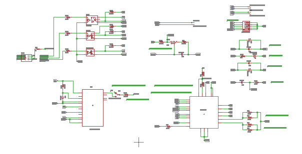 Schematic PDF
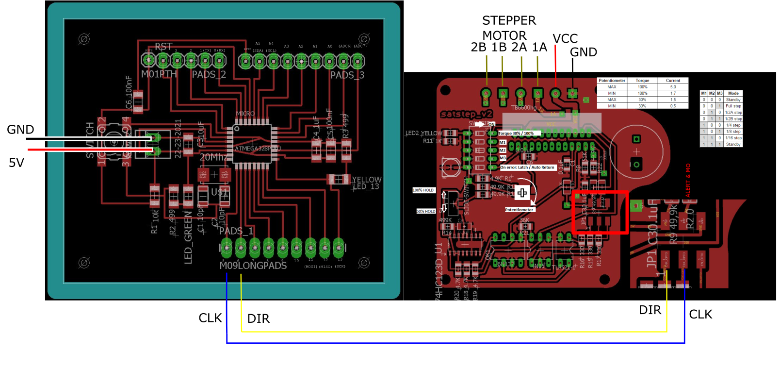 Wire connections to run a stepper motor with the driver
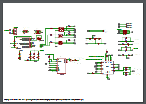 Schematic of (abandoned ) all in one card.
 week13 - input devices