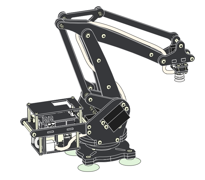
Uarm is an Open source desktop robotic arm which can be used for a multitude of purposes. Some of them being a pick and place, a simple laser cutter, or image processing projects.
We wanted to make this in our lab as we liked the design and the functionality of it. This has universal application for a 3-Axis machine.But we also wanted to add to the functionality of it. Hence we plan to make this arm mobile, by giving it a Gantry mechanism
The design of this arm is quite minimal yet sophisticated. The beauty of this design is that there are no motors in the arm, thereby reducing the weight of the arm and hence increasing the mobility and reducing cost of the motors.But there are a lot of moving parts.
For more details
The design calls for many moving parts which are not readily available in the our locality. Hence we have had to make or replace some of the parts in the design with those available with us.
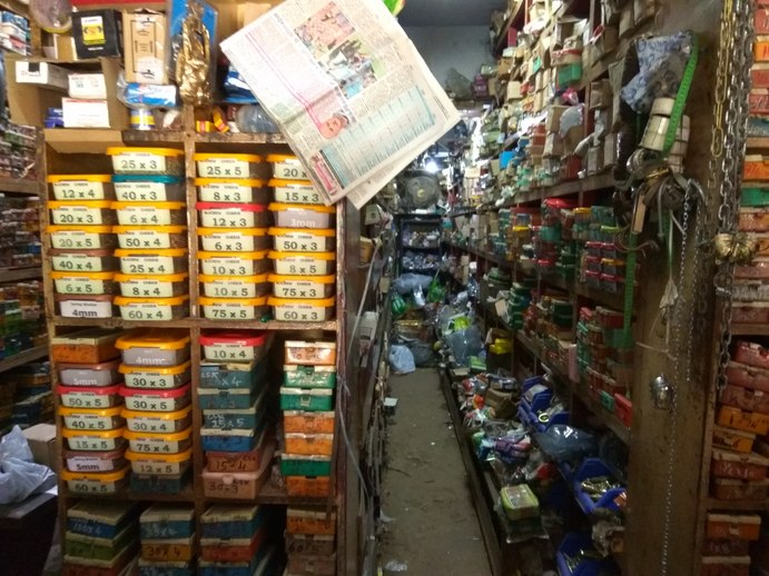
We have a place in our locality were we go to buy hardware. We walked till the end of the street and found a small shop which sells the screws we want. Walking into the shop was like when Harry potter walks into the Wand shop to buy a wand. There were long isles of dusty old boxes with screws and nuts in them. I asked the shopkeeper if he had any M4 screws. He asked about the length and disappeared behind the shelfs and came back with boxes of M4 screws. Not all the lengths were available, so I got the next closest one. In my mind, I could almost hear the the shopkeeper say "you don't choose the screw, the screw chooses you".
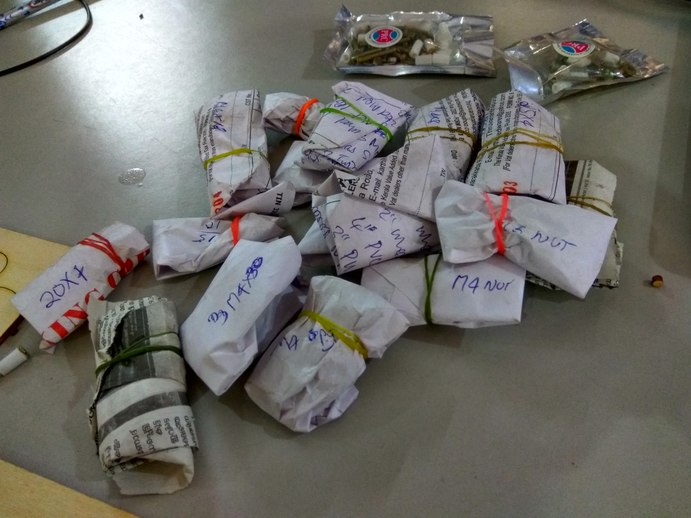
We could get all the screw and nuts, but the bearings are a different story. 4x8x3 flange bearings are quite hard to find.
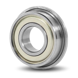
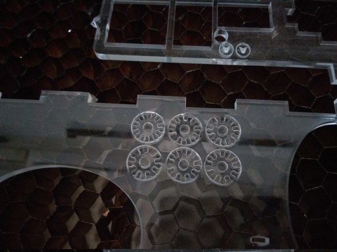
The bearings are indispensable, we need atleast 24 bearings in the original design, Hence to replace them, so we could prototype the design I came up with a plan to make a spacer that is the same size as the bearing and which will fit on the M4 screws. I calculated the dimensions after referring about the bearing online, and my friend Ajith 3D printed it.
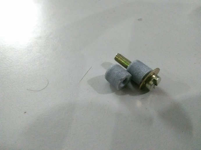
This is the design which we 3D printed, the design was for 6mm acrylic which we plan for making the final thing. But the prototype is 3mm wood, hence the extra space is there.
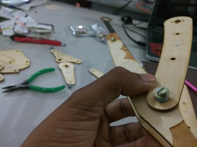
It works fine. We tried a couple of different dimension to see which would provide a close fit, but still allow the joint to move freely.
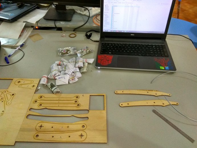
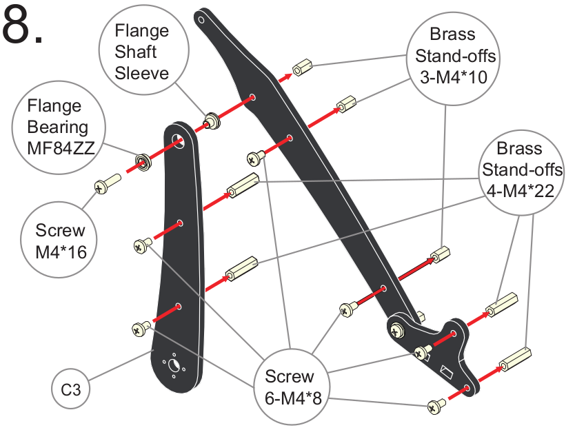
Our first job is to really understand the design of the Uarm, and see if we have the parts available to make them in our lab. hence we decided to make the arm in wood first. we laser cut a few piece of scrap wood we had, and started building the arm.
The assembly was harder than expected, since we don't have all the exact parts, hence we have to stop and figure out what can we use to replace a part we don't have. At the same time we were 3D print the standoffs as we could not find buy them.
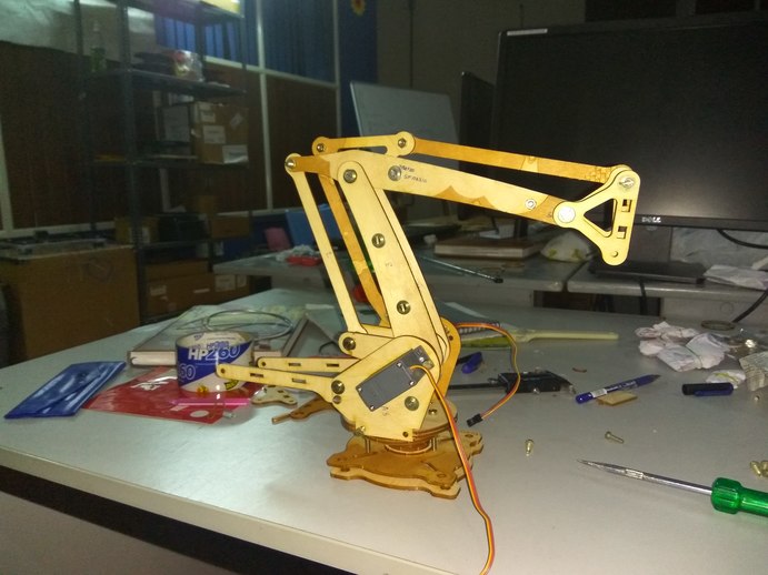
The arm took more than 12 hours of assembly, Most of the time was spend figuring out the replacement parts. The assembly instructions are really good. Once you start assembling, you begin to understand the design.
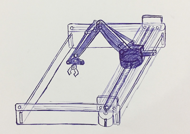
I really liked the chamfer rail gantry design by Jens Dyvik. As a Mechanical engineer, I really appreciate the work he has done. He has managed to solve a lot of problems involved in making a motion system. The design is really simple and straight forward.
You can find it on Github.
Since we don't have the bird beak bit required to cut v-rails on both sides at the same time. I'm going to have to switch over to the chamfer rails.
The next problem is the availability of materials. The High density plastic which we require for cutting the rails is not easily accessible in our region. And the cost is significantly higher. Hence I'm choosing to stick to the fab inventory and go with 6mm acrylic. Now this poses another set of challenges.
Jens design was for material thicker than 10mm. I understand that we can use grasshopper plugin to change the design, but I'm not familiar with it. Hence I'm going to try a really hands on approach and bolt together two pieces of acrylic.
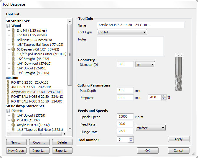
In our lab we have never cut acrylic using shopbot hence I had to start from scratch and figure out the machine settings. I began test cutting the acrylic with different settings based from the original bit settings. I know acrylic is denser than wood and hence I reduced the feedrate, plungerate, etc.
Cutting out acrylic is a bit tricky, if the feed is high it might melt and deposit on the bit. Start with a really low speed and progress up. i started with less than half the feedrate of wood and proceeded to find the optimal value.
The cuts came out pretty good, the feed can be increased if necessary.
I understand from Jens documentation that the shopbot bed has to be perfectly level. Well the sacrificial layer in our shopbot has seen better days, there are some variations in certain places. I found a good place and decided to fit my sheet there.
You have to be really careful when fixing acrylic to the bed. If you screw it in with large force then the sheet will crack. It happened to me twice. Alternately use some washers to spread the load of the screw.
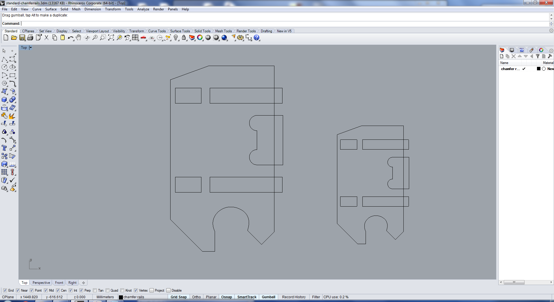
The glide block is designed to slide on the chamfer rails. Jens original design requires a material thickness of 10mm or above. We only have 6mm acrylic. Hence I scaled it down to one which fits into 6mm acrylic.
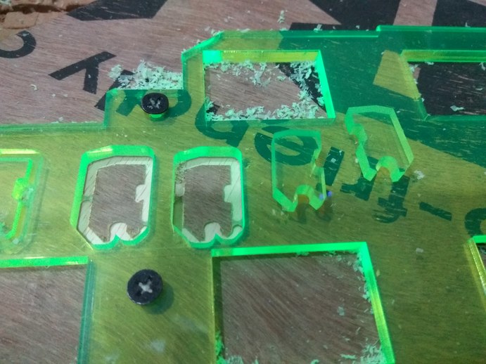
The scaled glide blocks I cut in shopbot. Its really tiny. I gave 1x1mm tab in hopes that the part would not lift out of the material and hit the spindle while cutting. After one cut i changed the tabs to 1x1.5mm but because I'm using an Upcut mill the part still lifted off, but this is only after that cut has finished. Hence not that much of a problem.
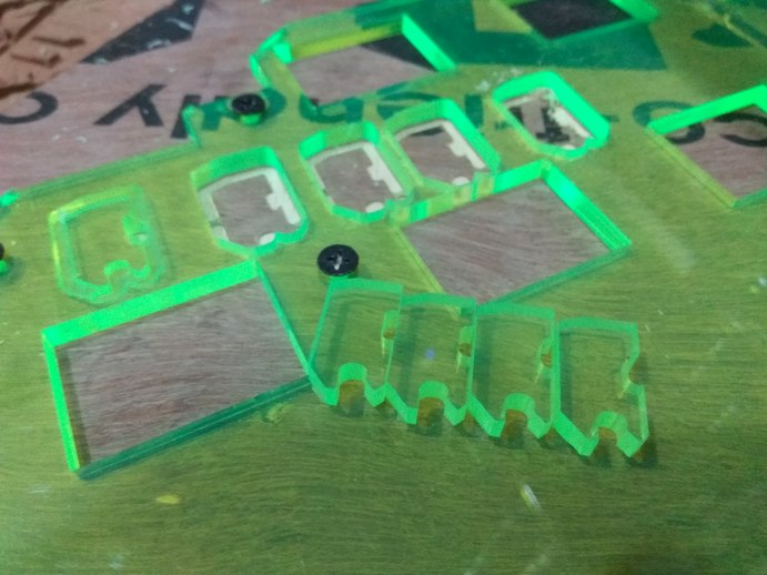
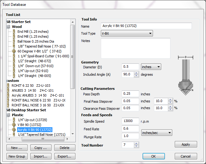
The reason we have to use the shopbot and not the laser cutter is because we have to cut a 45deg chamfer on one side of the rail. the chamfer serves the purpose of aligning the glide blocks on the rails. Hence it is a requirement.
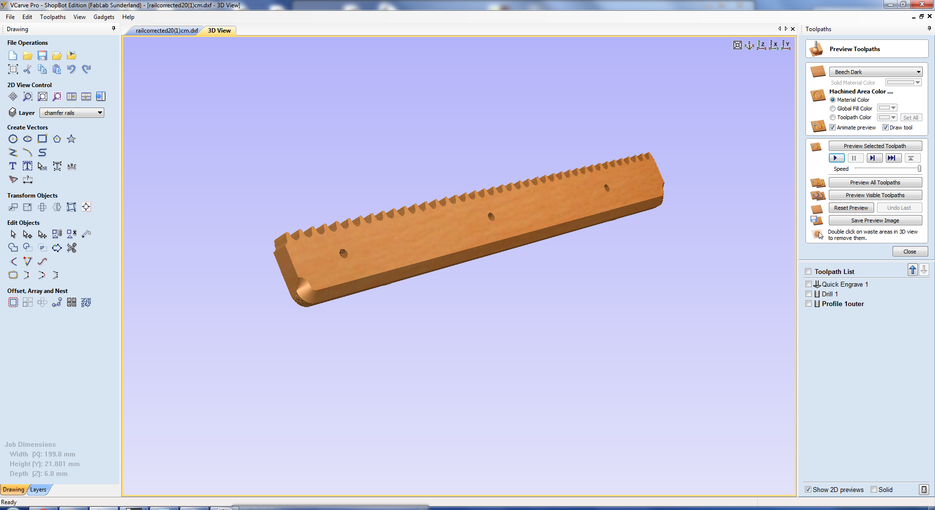
In V carve I set the tool paths and changed the machine settings to cut with acrylic. The sequence is to first cut the chamfer, then Drill the holes and then cut the teeth.
For cutting the chamfer we have a 90Deg V-bit, which we use for engraving. I cut the chamfer with the V-bit after changing the machine setting to cut acrylic.
The rails were cut with a 3mm upcut bit. the cutting was smooth and the teeth are fully formed. I've given 1x1.5mm tabs to keep the cut portion from lifting off the table, and it held nicely.
The cut came out good but since we are using acrylic the surface is not as smooth as I would have liked, but which can be fixed with some lubricants. I'll see if I can find some low friction plastics in the future.
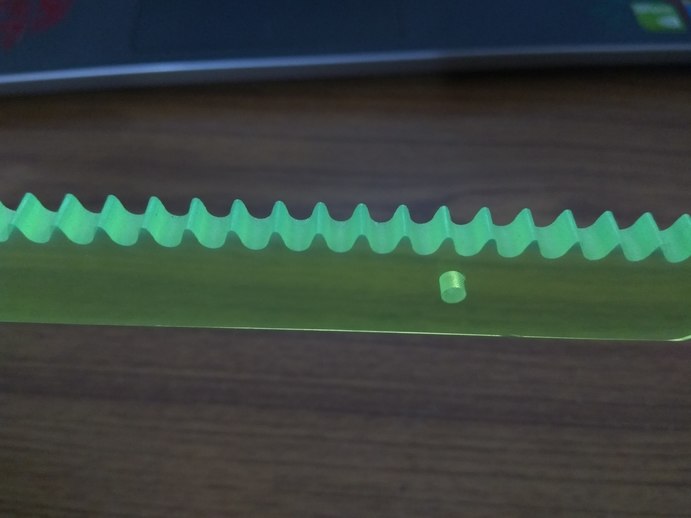
The teeth are good, there was no noticeable change in the profile of the teeth.
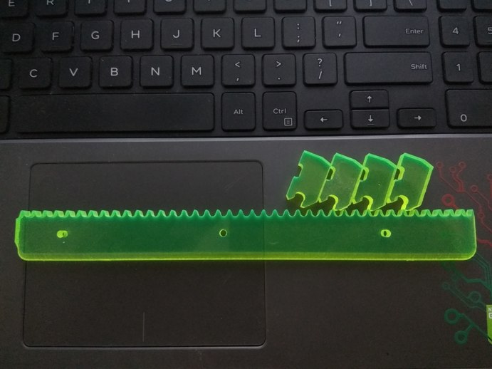
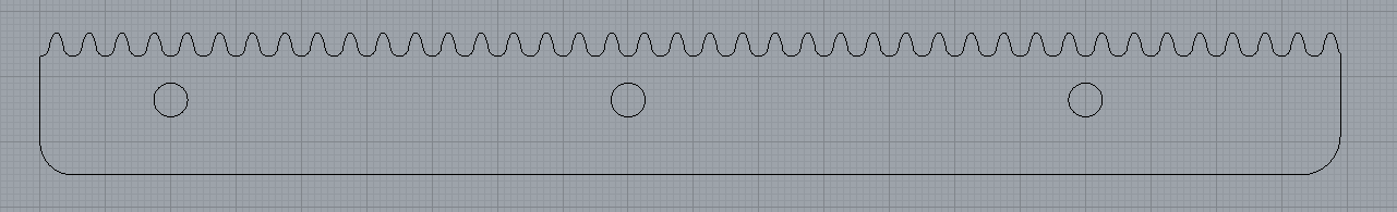
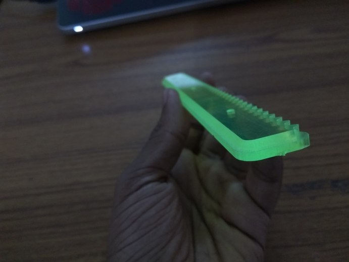
The main purpose of this test cut was to see if it was possible to make the chamfer rails out of 6mm acrylic. I have removed some of the additional features of the rail for simplicity. The next step is to cut the final rail.
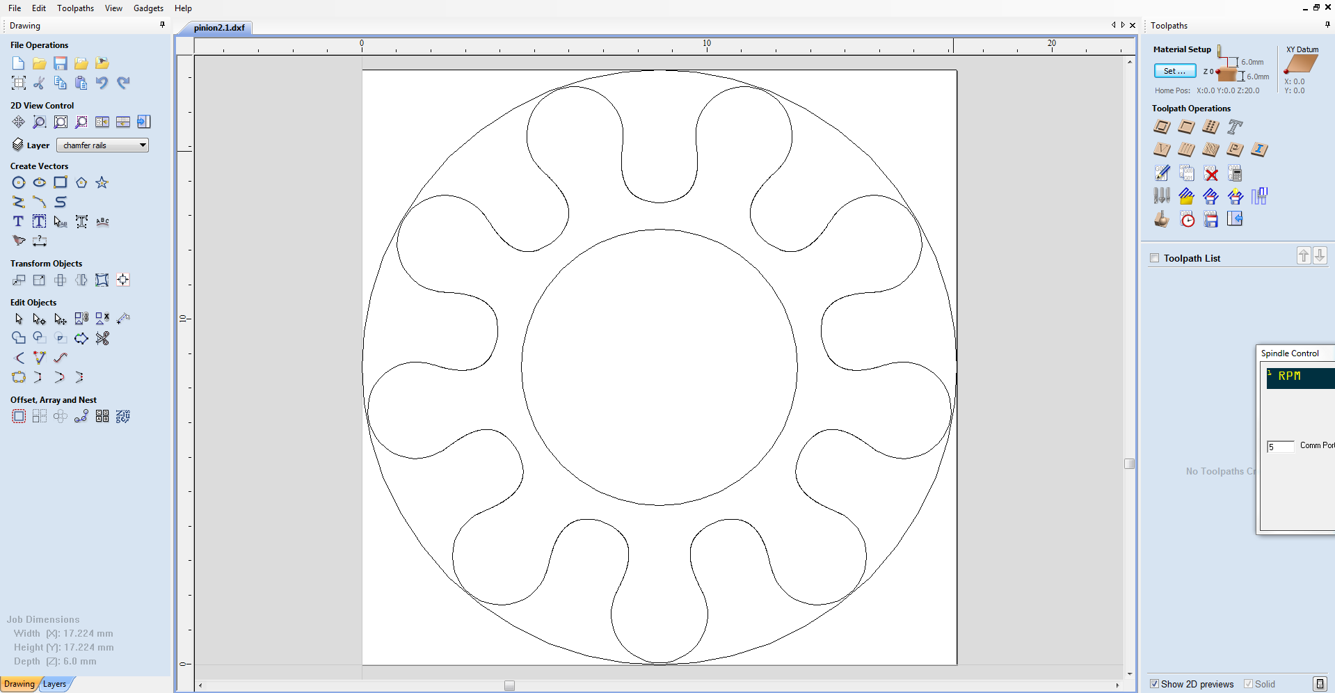
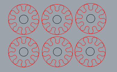
I have tried to cut the pinion on shopbot but I realized some portions of the pinion was smaller than 3mm. hence the only option was to cut the pinion on the laser cutter.
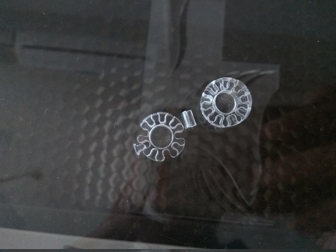
The laser cut pinion came out good, I have reduced the cutting speed a bit to get as smooth a surface as possible. I have taken extra measures to ensure that the laser was properly focused to reduce the effect of the laser beam diverging at the bottom.
Note: When cutting gears with a laser cutter, you should take the kerf of the laser into account. Kerf is the width of the laser. Change the design file to offset the sides by half the width of the laser kerf.
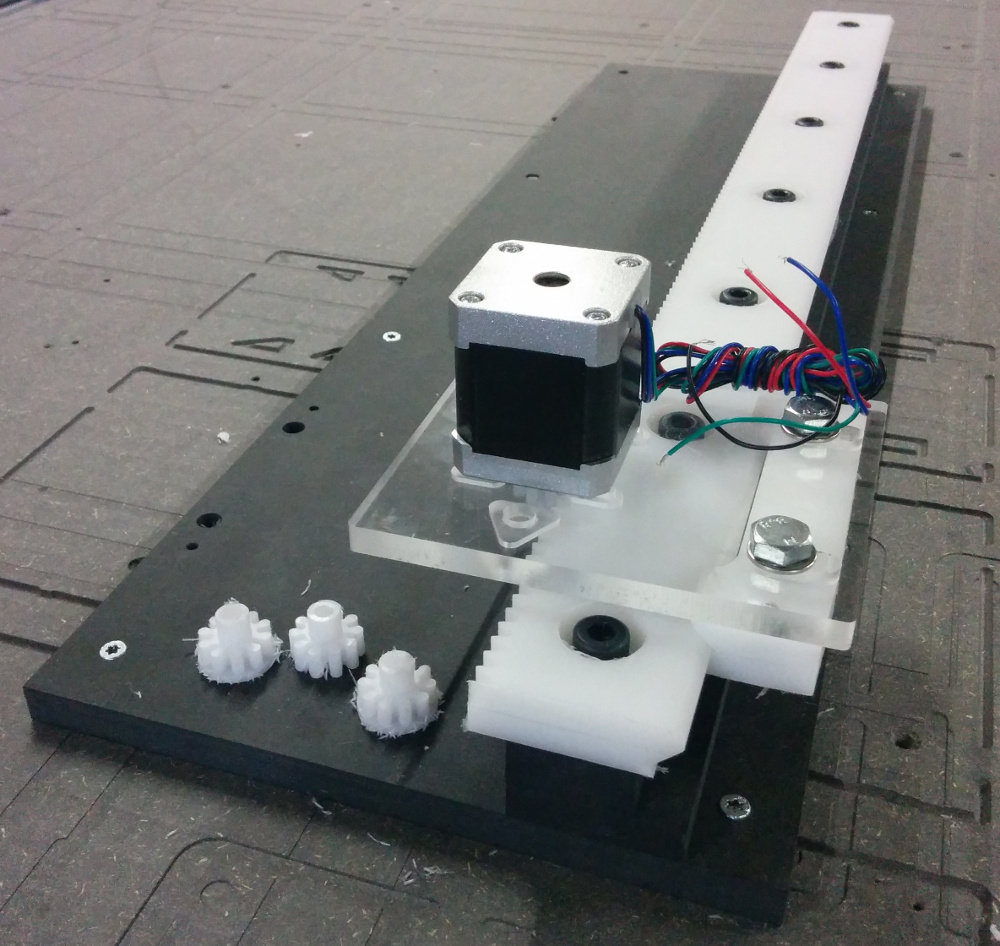
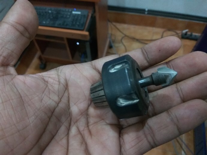
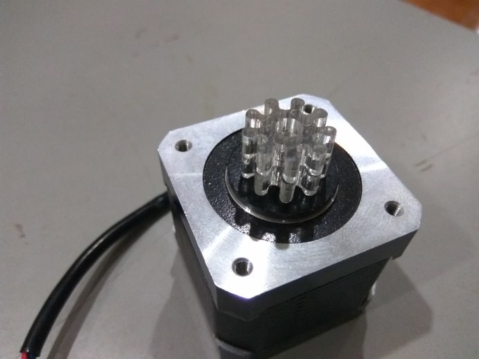
The next job is to connect the pinion to the shaft of the stepper. To do this we need a coupler, Since i did not have time to 3D print a coupler for this pinion i decided to tweak the dimensions a bit and press fit the gears into the shaft.
The shaft of the stepper motor was 5mm, hence I gave values in between 4.9 and 4.7,a nd cut two sets of each. 4.8 Fit well it was a tight fit, which was what I wanted.
In this weeks review I was called up in the random generator and I talked with Prof. Neil about my plans to make the rail. Neil advised me about the problems with using acrylic as the main member for the rail. Acrylic fails by cracking, hence it is not a good material for making something which will be exposed to dynamic loading conditions.
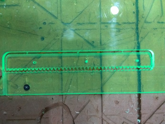
I had faced this issue a couple of time when I tried to fix the acrylc to the shopbot bed. It cracked where I screwed the board to the bed. This was a warning sign, I used acrylic because it was the only material available in our lab other than wood. I wanted to test how the material would behave under the circumstances. I made a 20cm rail as a test to find out how the rail would look like when cut on the shopbot. I though since the arm was not that heavy and the load could be withstood by the material, I could fix the acrylic rail on to a stiffer piece of wood and use it as a linear axis.
Acrylic is too fragile a material to be used for such application. Even if I finish the rail, it might break when I fix it to a backing plate.In the end I decided not to make it with acrylic.
In the mean time since the prototype for the arm was finished, our electronics engineers started programming it to make it move. They are using arduino to control the servo motor, since the servo only needs a pwm pin to run. The servo is powered externally and the input is set via arduino. The torque rating on the servo is not that high, only 4.3kgcm which is not enough to move the weigh of the arm when fully extended. That is why the motion is erratic. The servos are being over worked.
Since my plan with acrylic was busted I was looking for another material to try making the rails with. I searched in my local shops and online for HDPE or Delrin but local shops didn't have it and ordering online would take a lot of time.
This is when I found some pieces of scrap Eco Board (PVC foam boards). In my preliminary analysis I found the material to be strong and bendable. I though I could try the rails with the them, and they were much thicker than the acrylic sheets (18mm).
Eco board are much softer than wooden boards as they are made out of PVC. Since this was a scrap piece I wanted to try making the rails with it.
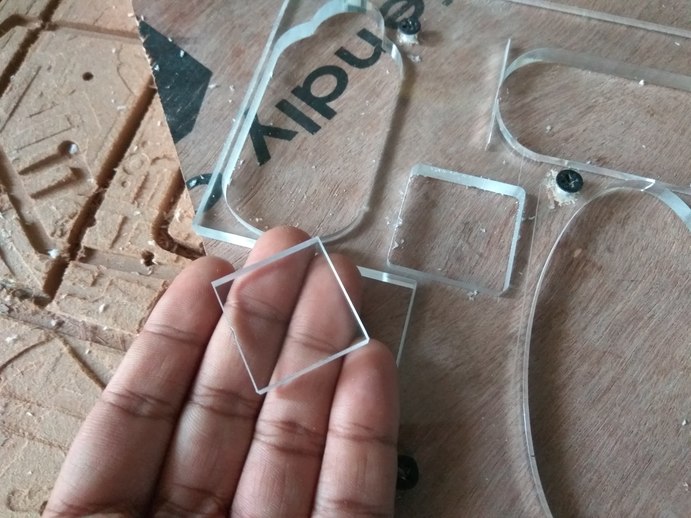
Since I have never used this material before I wanted to test cut a small piece so that I know how the material behaves and what kind of surface finish I will get.
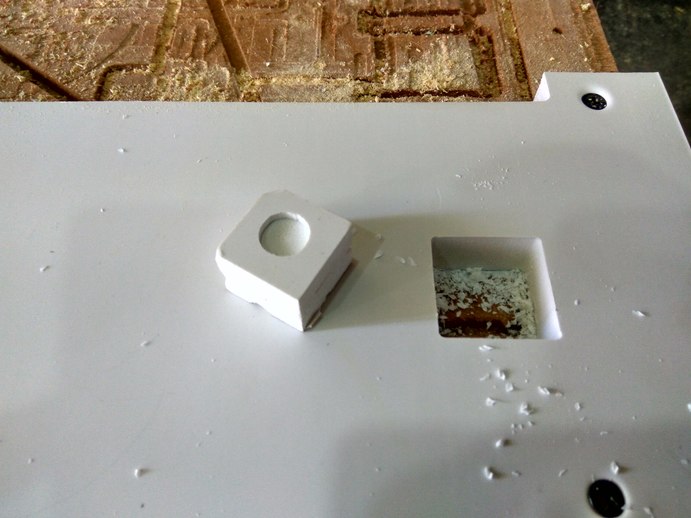
I made a small 2cmx2cm square with a circle on top and pocket out the circle. The surface finish was good and the material cut through beautifully.
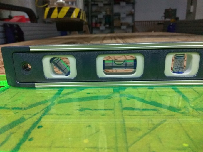
I made sure the board was level using a spirit level and proceeded to cut the chamfer on it using the V-bit. The cut was good but the surface finish is not that great.
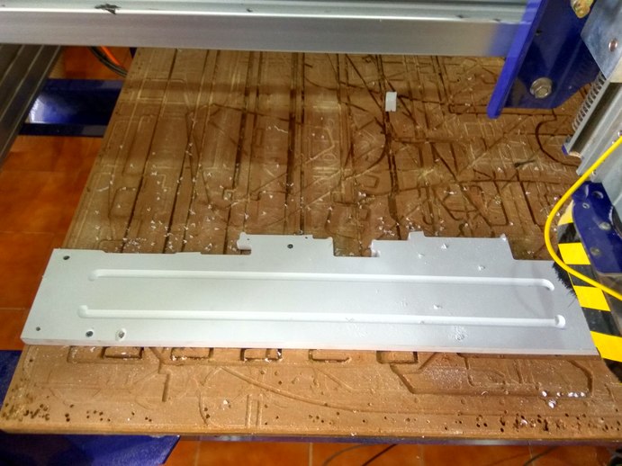
I should have given two cuts, a rough cut and a finish cut at higher speed and lower feed rate.
I then proceeded to cut the rest of the rail. I used the 6mm bit to pocket the area in the middle, before the teeth, where the a lot of material has to be removed. I then switched out the tool to a 3mm bit and cut the teeth profile, pocket for the screws and the final cut lines. The cut came out beautifully.
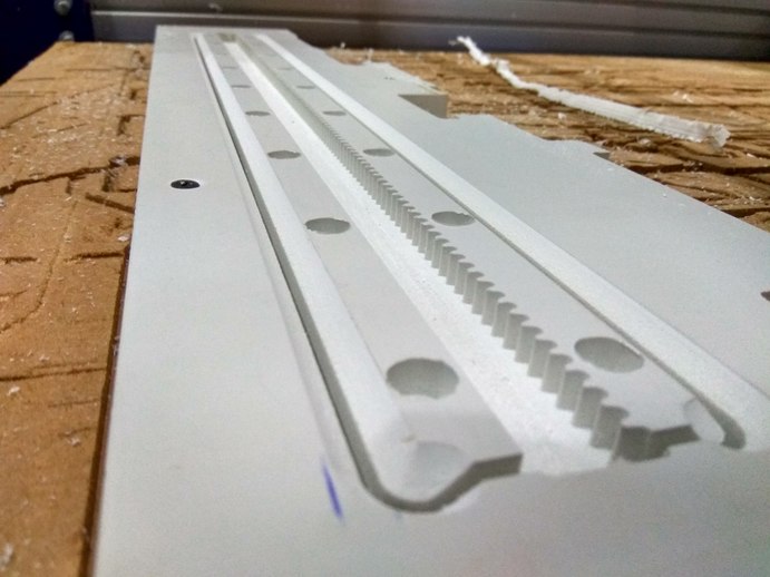
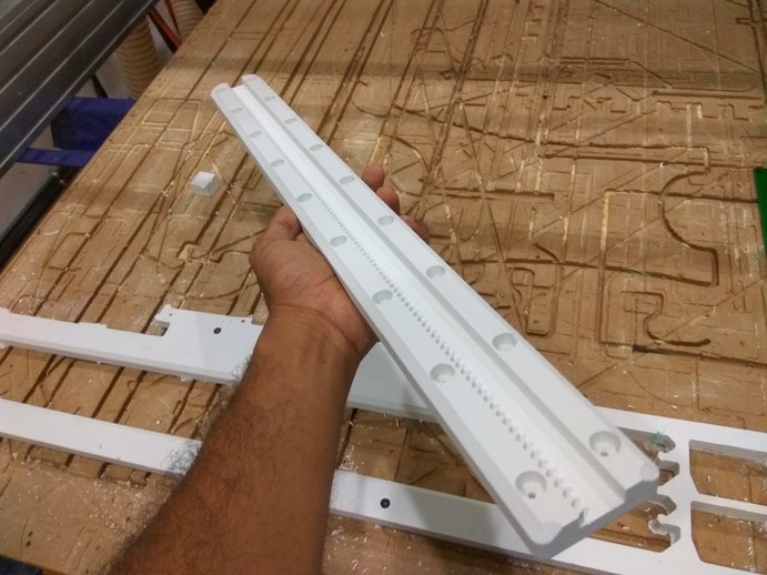
The rail is 60cm long and 18mm thick, The ecoboard is holding it shape nicely, but if you apply pressure at a sharp corner, you will deform the material. Its not the idea material for making a mechanical structure.
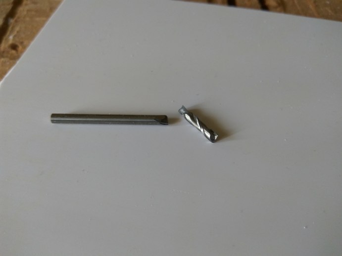
When I was cutting in shopbot, I had to change the bits frequently, this meant that I had to set the zero for each new bit. After pocket cut i switched from a 6mm bit to a 3mm bit. I was zeroing the bit by using the contact plate of shopbot, I tested the plate against the bit to ensure that input was comming in and I went ahead to give the option for setting the Z- zero. Only this time the spindle did not stop when it touched the plate, It kept going and in a snap the bit broke. I quickly hit the stop button to prevent any further damage.This was the first time I had broken a bit, so the experience was rather scary.
This reminded me how dangerous shopbot really is. One moment things are going fine and the next moment something could go wrong. You need to have a healthy respect for the machine and treat it that way. This is not a machine you can turn your back against.
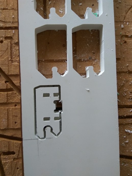
I had cut out Jens guide block, with the only modification being I increased the scale a bit so that it can accommodate the material thickness of 18mm. After cutting out only I realized one critical mistake. Jen's guide blocks were designed for tougher material, I cannot simply replicate them on a weak material like PVC foam.
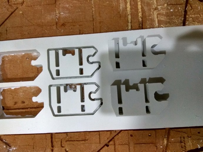
The guide blocks are really big but weak, another mistake I made is to pocket out the interior of the block to the full depth. I had realized it only after going through his documentation properly.
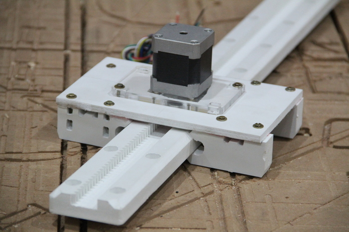
When I test fitted the guide blocks on the rail, I did not like how they stood, they were really big and the pockets were not cut correctly. hence I decided to modify the design a bit and cut out new pieces.
The main thing I changed was that I pushed the inside grooves higher and cut the height of the blocks by 1/3rd its original. Now the blocks were compact and are suitable for a weaker material like PVC foam.
The cut came out well, I like the design , It is more compact and fit my needs. I then cut out three more of them to fit to my rail assembly.
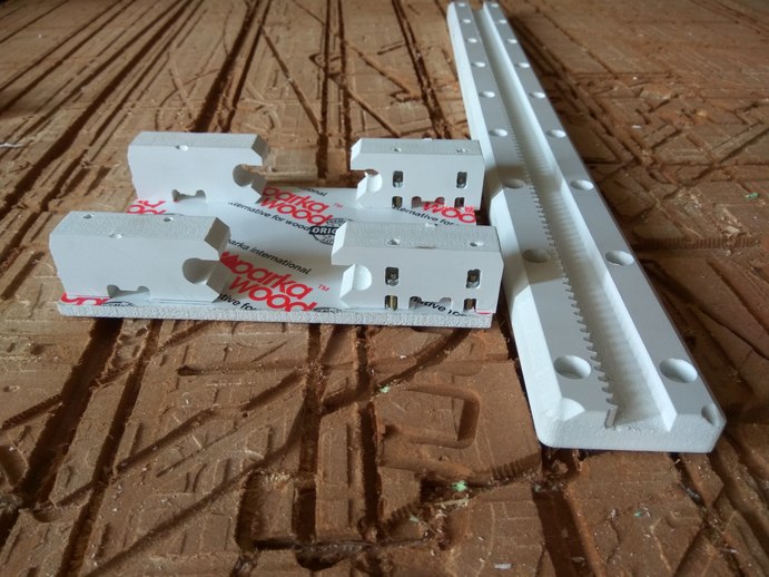
I attached the guide blocks to the top plate using M3 screws and nuts. The assembly was done manually, by using a drill to make the holes and inserting the screws in them, tightened by nuts.
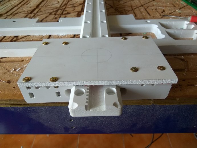
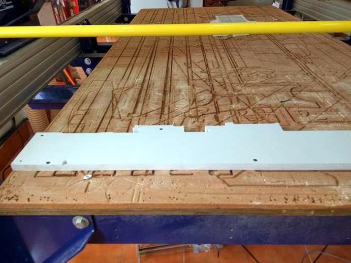
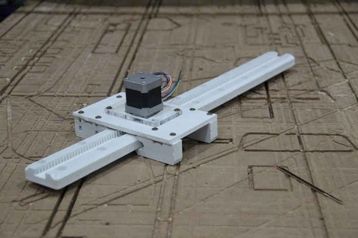
The next step is to attach the motors into the top plate. I had laser cut the motor plate in acrylic some time back. I attached the motor plate to the stepper using screws. I then attached the motor along with the motor plate into the top plate of the guide rail.
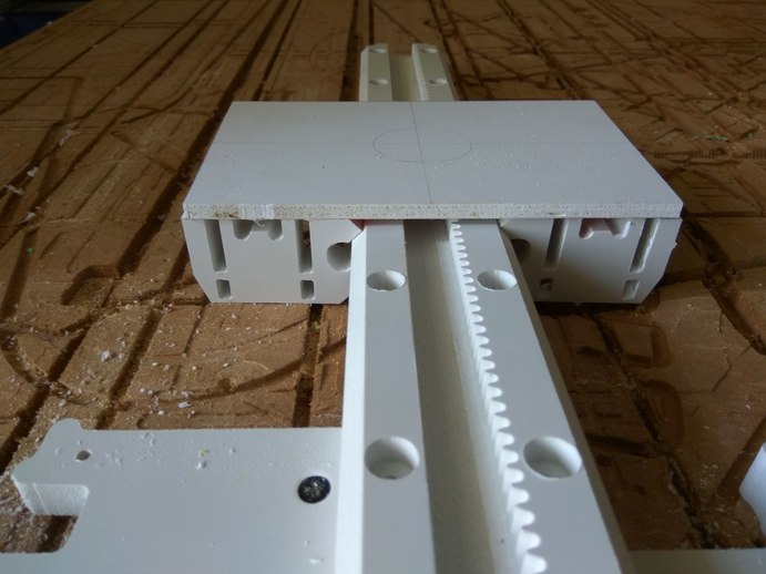
Next we had to come up with some way to fix the arm on top of the guide rail. For this I planned to press fit a small rectangular piece on top of the stepper and attach a base to it. So that the arm can be fixed to the base plate.
I designed and cut a hollow rectangle to fit on top of the stepper motor. The fit was good and strong, it will support the weight of the arm.
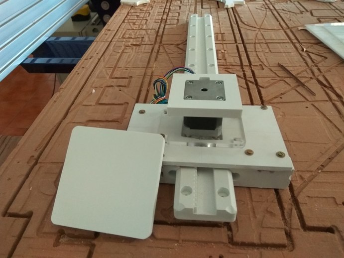
Finally the guide rail is done. There were some complications during the machining and assembly, but I was happy it came out well. I'm a bt worried about the material, Foam board is a very soft material. Jens design works really well. I will use it in the future.
rahulsrajan.com
rahulsrajan01@gmail.com
Trivandrum, Kerala ,
India.

Technopark, Kerala, India