Exercise 7 - Computer-Controlled Machining
Assignment for this week
Difficulty in Designing
For this week assignment, I have no idea what to create or how to make something Big. I was told that we need to use computer to generate the design using the various CAD software like Fusion 360. No nails, screws or glue are to be used to put the parts together.
As mention in week 3, being a Non-CAD user, I find it extremely challenging to draw objects and visualize it from a 2D to 3D let alone drawing it out in Fusion 360. Seriously, apart from the parametric settings, I have already forgotten most of the stuff I learnt. And now I have to face new challenge in designing and drawing it in Fusion 360 so that all the pieces can fit nicely together.
After completing the design in Fusion 360, have to send the design to be mill in the CNC router. OH NO !! another stress week. Neverthless, I still have to pull myself together and get myself familiar with the software and milling machine used.
Familiarization and Kerf Finding for CNC Router
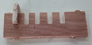
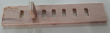
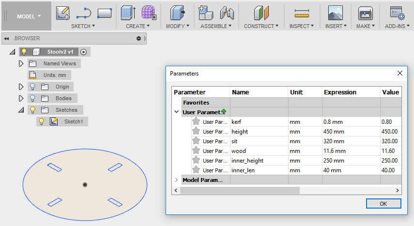
The CNC router we have in Fablab @ SP is the Signvec SK2030. We are using 8 x 4 feet plywood for our project. Thickness of the material is 11.6mm. A simple fitting test done together with my classmates (Jeff and Hong Guan) shows that +0.8mm would be a good press-fit setting to use. You can browse here for their website for more information.
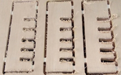
A further test has been carry out to use Spindle at 8000/9000, Speed at 3000/4000 and Speed Rate at 10%. The time taken varies for each settings. However, one need to consider the time taken to complete each milling. Setting Speed Rate too low althought the workpiece is in a much better shape but looking at the time taken to mill a test kit, cant imagine how long it will take to mill a bigger piece. I will be using Spindle at 8000, Speed at 4000 and Speed Rate 60%.
  |
 |
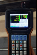
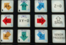
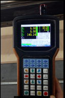
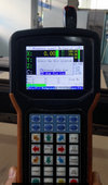
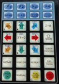
CNC Router Controlloer
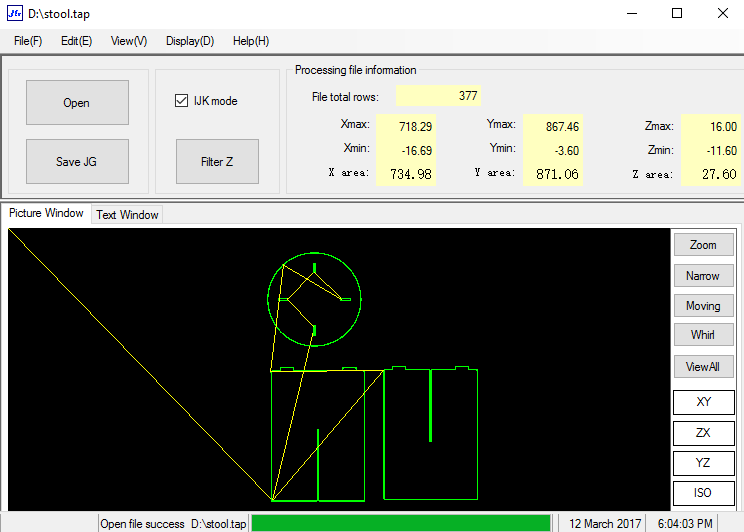
Signvec SK2030 CNC is controlled via a 3.5 inch jog-shuttle controller. It requires a file format of "JG", so we need to use the PC loaded with a software called CNC_Change to convert the “tap” file (which contain the G-code) to the format the CNC machine can understand. The JG file generated is then copied to a thumb drive and plugged into the SK2030 jog controller.
 |
The following are the steps to mill
- Press the X+, X-, Y+, Y-, Z+ and Z- keys to move the head in respective direction so to determine the XY origin by pressing XY=0 and the Z origin by pressing Z=0.
- Press F4 to load the gcode
- Select the file location > U disk file list and the OK button to read the file
- Press the OK button to register the parameters for the settings
- After determine the X,Y and Z origin. Simulate the cut by doing an air-cut to verify the operation
- To start cutting process, press the Run key and then followed by OK button
- During the milling process, press Shift F2 to decrease spindle motor speed and Shift F3 to increase the spindle motor speed by 3000 rpm each time.
- Press the UP-arrow (Y-up) or DOWN-arrow (Y-down) keys during milling changes the feedrate by 5% each time.
 |  |
 |
 |  |
 |
 |
Some Important terms use on Milling
Making reference to sites like Makezine , Precise Bits, Destiny Tool, PDSspindle and Using Milling.
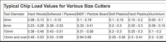
Chip load
It is a term used to describe the thickness of a chip removed by one cutting edge of the tool. Chip load is sometimes referred to as ‘feed per tooth’.
The formula to calculate chipload is:
Feedrate / (RPM x NumberOfFlutes)
If the chip is too small, the heat is transferred to the cutting tool causing prematurely dulling. Too high of a Chipload will cause an unsatisfactory edge finish, or part movement.
 |
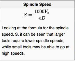
Spindle speed
It is the rotation speed of the tool and is measured in revolutions per minute (rpm).
 |
Feed rate
It is the speed at which the material is fed into the cutter. The formula to calculate Feed rate:
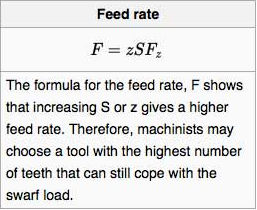 |
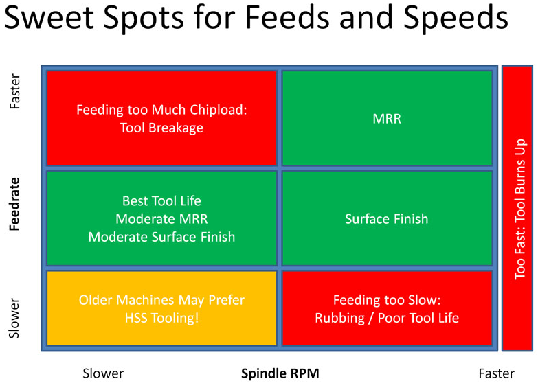
The CNC Cookbook website gives a good description of the various problems such as tool breakage, poor surface finish, poor tool life, machine chatter and material removal rates resulted from wrong settings.
For the SP Fablab CNC, we uses a 6mm, 2 flute end mill cutter, setting the spindle speed at 8000 rpm on softwood.
Feedrate = 0.28(chip load) x 8000(rpm) x 2(no of flute) = 4480mm per minute
 |
Step down
The distance in the z direction per pass that a cutting tool is plunged into the material
Step over
The maximum distance in the x/y direction that a cutting tool will engage with uncut material.
Design the The Stool using Fusion 360
I have chosen to do something simple that is drawing a stool. I browse the following sites Fusion 360 Beginners, Stool and Coffee Table to get some guides and ideas on what to draw and design in Fusion 360. It give me a rough idea on how to create one of my own stool in Fusion 360.
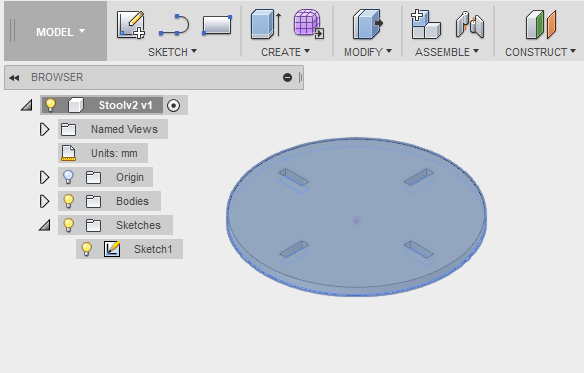
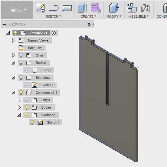
With reference back to Exercise 2 - Computer-Aided Design and Exercise 3 - Computer-Controlled Cutting write-up on Fusion 360. The following is what i have drawn using Fusion 360.
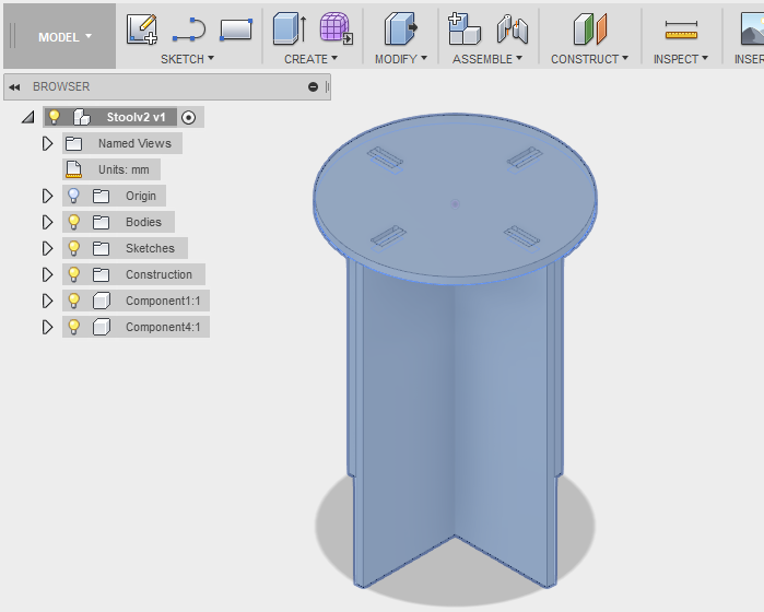 |
Like in Exercise 3, create parametric setting under Modify > Change Parameter. Next like in Exercise 2, create a sketch in 2D form for each part of the component then using Extrude (E), to make the 2D form into 3D.
 |
 |
 |
Once all the components have been extruded, we are ready to move to the next process.
Preparing Fusion 360 for milling
Before we send the stool design for milling, there is a step that need to be done. That is to generate the Gcode for milling. The file created is in tap format. With reference to CAM in Fusion 360 and Introduction to CAM/Toolpaths. I follow the steps and guide to create the gcode needed for milling.
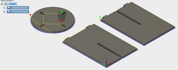
- Run new setup in Fusion 360 under CAM
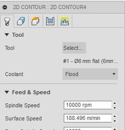
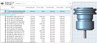
- Select 2D > 2D Contour > Under Tool > Pick 6mm Flatend Mill
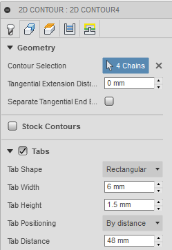
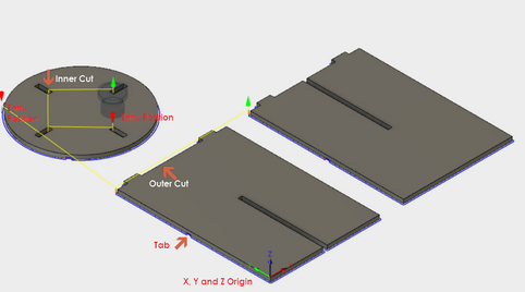
- Under Geometry > Select the Set the X, Y and Z origin, pick the direction for inner cut under contour selection, insert tabs for mill to prevent stock from flying out
- Under Height and Passes, use default settings
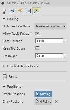
- Under Linking, define the entry position for the mill (optional) if not the system will auto assign the milling process.
- Repeat the same steps for outer cut
- Select Actions > Run Simulation to simulates toolpath and stock materials removal
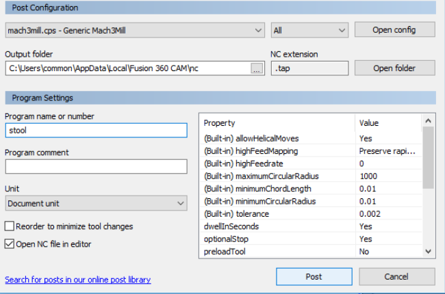
- Select Action > Post Process to create the gcode needed for milling (Will be choosing Generic Mach 3 Mill for my milling machine). File with extension *.tap will be created.
 |  |
 |
 |
 |
 |
 |
Conversion of Gcode for JG
Upon creating the tap file from Fusion 360, we require the CNC_CHANGE (JG) Program to verify the formatting of the gcode that it reads. Once verifying done, saved as a .JG file extension and it is ready for cutting on the Signvec SK2030.
 |
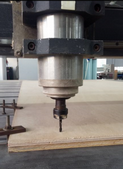
Milling the Stool
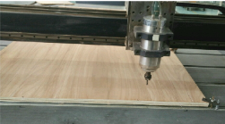
With the save JG file store into a thumb/flash drive, plugged into the SK2030 jog controller we are ready for Signvec CNC controller to start the actual cutting. Refer back here on how to use the Signvec CNC controller.
 |
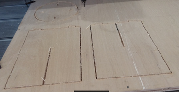
Once my stool has been cut out from the stock material, the tabs were removed using a hammer and chiesel.
 |
The milled pieces were then sand down to clean up the edges from the milling process. The stool was then assembled.
 |
Download the files for this week.
- Stool created in Fusion
- Stool with tap extension
- Stool with JG extension
My Thought
During our process in doing the testing to determine what is the best fit. We realised that it requires many testing before conclude what is the best fit and what is the ideal setting during the milling process. This is because we are not familiar with the software used in both the CAM in Fusion and the CNC Router. It doesn't help that the software CNC Change (comes with the router) was installed only in the PC that was meant for the Signvec SK2030 use. Although we conclude that +0.8mm was the best fit but that was without considering the use of dog-bone edges in the slot. As for the milling machine settings, although using speed rate of 60% and spindle speed 8000. The speed rate can be further increase.
This is the first time I managed to mill my own creation stool after designing it in CAD software - Fusion 360. Is really a good learning experience for me, it forced me really to learn the software from Fusion 360 > CAM > JG > CNC router. Otherwise, I dont think I would ever done something like that. I really hope that I can find time to come back and re-do or remake something apart from stool irregardless of whether I am able to complete this course or not. For now, I have to move on.