Exercise 3 - Computer-Controlled Cutting
Assignment for this week
Vinyl Cut
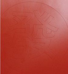
The Vinyl cutter I used was Silhouette Cameo. Since we are still in the Chinese New Year period, I will be using the chinese character "發" , meaning to become wealthy to test on the silhouette cameo. The entire cutting process is as follows:
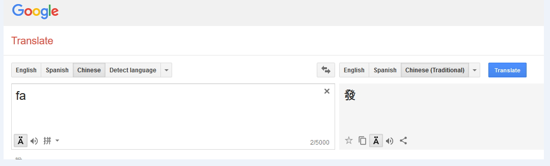
- Search for the word "發" in google translate, copy the text
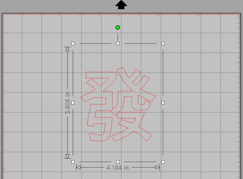
- Open the Silhoutte Studio that comes with Silhoutte Cameo, paste the text and resize the character to desire size
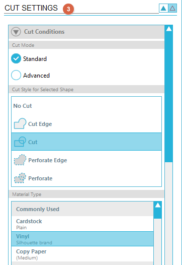
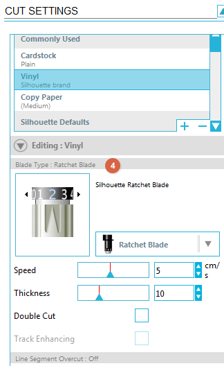
- In the Cut Setting, select the Cut Mode, Cut Style and Material Type
- For the Blade type, ensure the blade is in the right depth. The recommended setting from the manufacturer is Blade depth "1" but i will be using Blade depth "2", speed "5" and thickness "10"
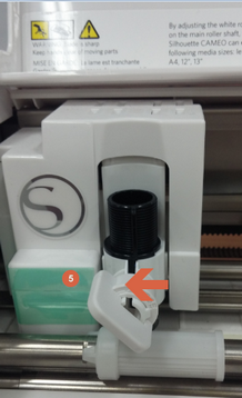
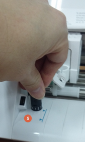
- At the cameo machine, unlock and adjust the blade
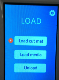
- Place the vinyl on the cut mat and press load cut mat"
- At Silhoutte Studio, click "send to silhouette"
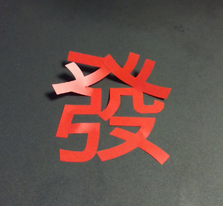
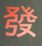
- When cutting is completed, cut out the area of the design, peel and place it over to your desire surface
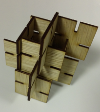
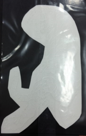
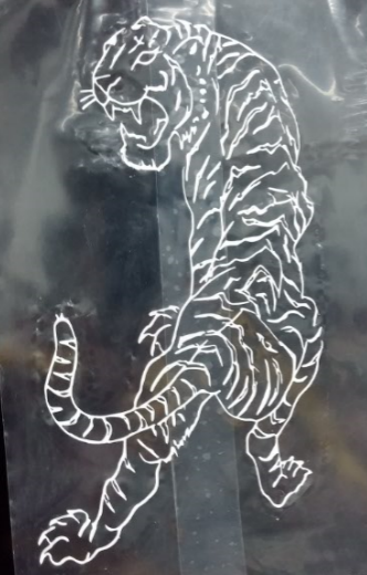
- Next, I try a more complicated design and then transfer the image using a transfer tape.
 |
 |
 |
 |
 |
 |
 |
 |
 |
 |
 |
File for download here.
Laser Cut
As a Non-CAD user, i find it extremly challenging to draw objects and visualize it from a 2D to 3D. With reference to past year archive, Ponoko and some online explaination on parametric press-fit construction, I will be using Fusion 360 for this week exercise on Laser Cut since Fusion 360 has a parametric settings under the user parameters.
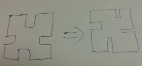
As this week schedule also crashes with our school student projects submission, therefore the priority was given to the full time student. While waiting for the availability of the Laser Cutter, I start to sketch on paper how I wanted the press fit box to look like and also thinking how can i sketch it in Fusion 360.
Finding the Kerf - Group Work
Before going into the laser machine to cut out the press-fit kit, we need to find out what is a Kerf. As mentioned in most of the reference websites, there will be certain amount of material being burns away during laser cut, so it is important to take into consideration the kerf when planning to laser cut any design in order to create the correct fit. For a more detail and to have a better understanding of Kerf, kindly visit this website.
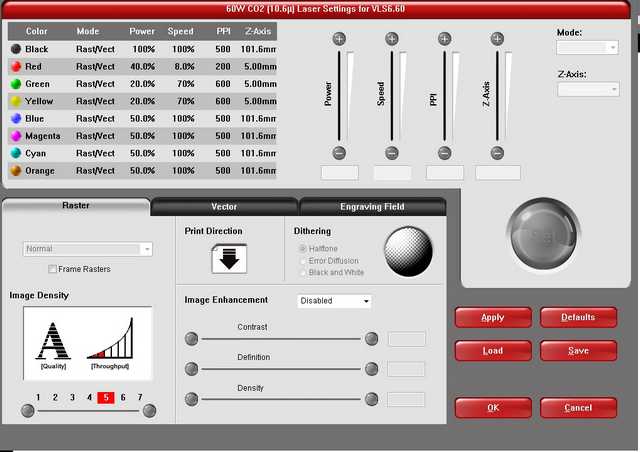
Fablab@SP are equipped with many different laser cutters. will be using the Universal Laser VLS660 to do the Laser Cut. The optimal cut through settings is obtained by adjusting the following
- Power - which is the strength of laser
- Speed - which is how fast the laser head move
- PPI - which is pulses per inch
- Z-axis = which is the material thickness
With the above and also some trial and error, the following predefine setting is determined.
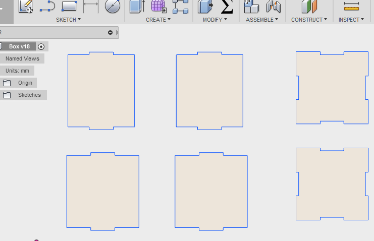
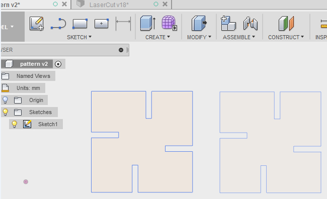
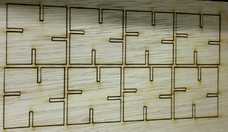
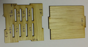
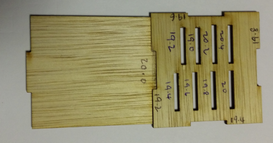
Next is to carry out the kerf test, with reference back to Exercise 2 - Computer-Aided Design for the write up on how to use Fusion 360. Started out by drawing a square in Fusion 360 with two male joint of 20mm and also another square with female joint with 19.8mm, 19.7mm, 19.6mm, 19.4mm and 19.2mm bearing in mind the material being burns away. It was then exported as dxf and transfer it for laser cut on a 2.3mm plywood.
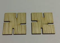
Test result as follows
- Test with 19.8mm, joint is loose, easily fall apart.
- Test with 19.7mm, joint is still loose, pieces still fall apart easily.
- Test with 19.6mm, joint is better but still loose and pieces can still move a bit.
- Test with 19.4mm, joint is quite fit.
- Test with 19.2mm, joint is tight fit.
Kerf for this laser cutter on this 2.3mm plywood is about 0.8mm
Drawing Tight Fit in Fusion 360
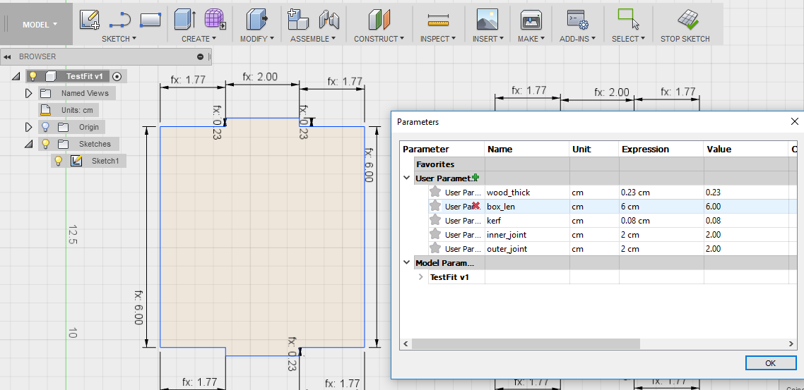
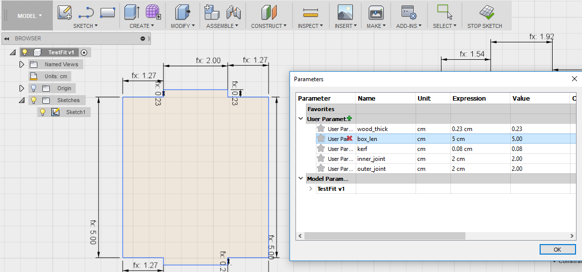
With the correct fitting determine, I proceed to draw the various part of the cube on Fusion 360 using the parametric feature. From the Modify tab dropdown, select "Σ"" symbol or Change Parameter, with consideration of the kerf enter under user parameter.
What makes parametric great was that at any time you can made changes to the shape created by changing the value set in the User Parameter. After which these set of value will apply to all the sides that are associate with the "Name" in the Parameter as shown. In this case, "box_len".