Exercise 11 Machine design
Requirement
- Group assignment - make a machine, including the end effector, build the passive parts and operate it manually
- Group assignment - automate your machine
- Document the group project and your individual contribution
For a more detailed documentation of our group project, check out the group page.
Planning
Like the week for Mechanical Design, none of us has programming background. Therefore we have decided that for this week Machine Design, whatever decisions made it has to be group decision and each one of us will still contribute, participate and collaborate as an individual.
Workload Distribution
Before we proceed to work on automating the machine, the group has met, discuss and distribute the workload as follows for this week machine design:
- Software needed to automate the machine - (Jeff/Ngiap Peng/Tiang Seih)
- Program and Test out in Windows platform - (Jeff/Ngiap Peng/Tiang Seih)
- Program and Test out in Ubuntu platform - (Hong Guan)
- Program and Test out in Mac platform - (Louis)
- Connecting the MTM Kit and Test Run on the Axis - (Ngiap Peng/Jeff/Louis/Hong Guan/Tiang Seih)
- Test the machine using hard coded coordinates on shapes and text
- Text - (Ngiap Peng/Louis)
- Shapes - (Jeff/Hong Guan/Tiang Seih)
- Documentation
- Creating/Updating the Group and Machine Design Page - (Louis/Tiang Seih)
- Photographer - (Hong Guan)
- Videographer - (Louis)
- Poster design for the MTM Group Page - (Hong Guan)
- Video creation for the MTM Group Page - (Louis)
- MTM Presentation - (Tiang Seih)
Links to my team-mates' contribution:
My contribution
In this group project on machine design, I was involved in the following area:
- Program and Test out in Ubuntu
- Connecting the MTM Kit and Test Run on the Axis as a group
- Test the machine using hard coded coordinates for shape
- Documentation - Presentation Poster Design
Program and Test out in Ubuntu platform
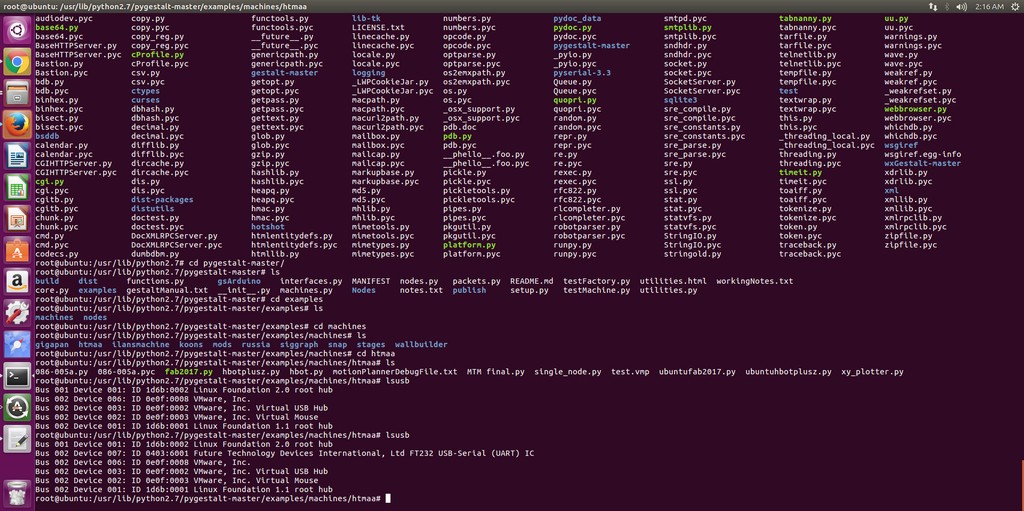
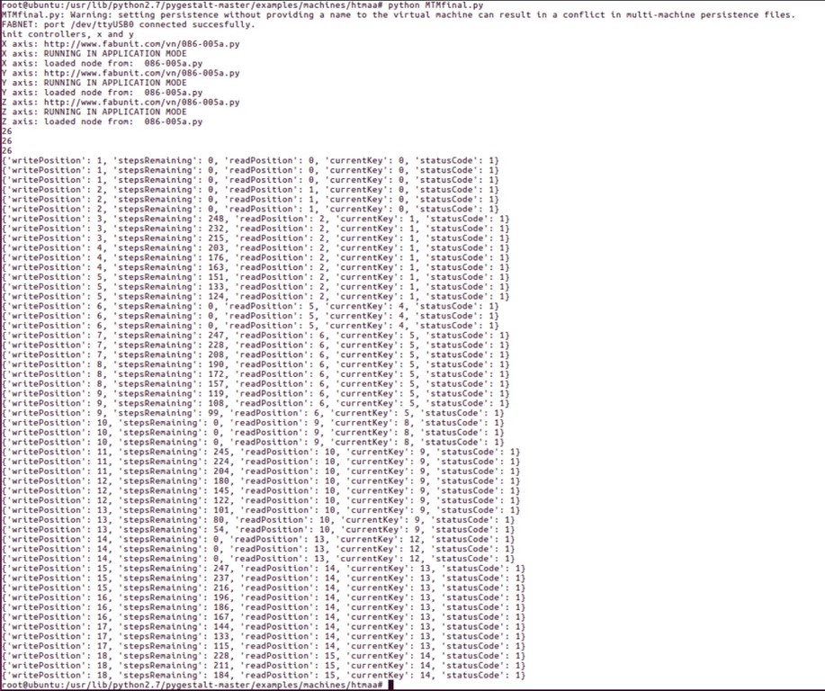
As my Laptop is the only one with 16GB memory to run both windows 10 and Ubuntu concurrently among our team member, so I have since week 9 got the unbuntu python environment ready and started on the testing for single axis and then three axis. Esentially, the python coding is independant of the OS platform. The only trick here is the definition of port connecting to FTDI interface.
As such I first power up the virtual machine and run ubuntu then after coonected the Gestalt node and stepper motor through the FTDI, I then use the command of lsusb to check whether there is a FTDI device connected to my Ubuntu system.
Communicating with the stepper motors
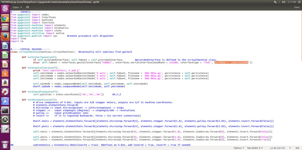
Modifying the example files found in ~\pygestalt-master\examples\machines\htmaa\, I was able to test the system, and ensure that my computer is able to talk to the machine. These are the changes I've made:
  def initInterfaces(self):
    if self.providedInterface: self.fabnet = self.providedInterface   #providedInterface is defined in the virtualMachine class.
    else: self.fabnet = interfaces.gestaltInterface('FABNET', interfaces.serialInterface(baudRate = 115200, interfaceType = 'ftdi', portName = '/dev/ttyUSB0'))
With that I started my one axis testing and a video clip was recorded as follow:
With the success of testing of one axis movement, I then move on to the two axis testing by running the following command in Ubuntu.
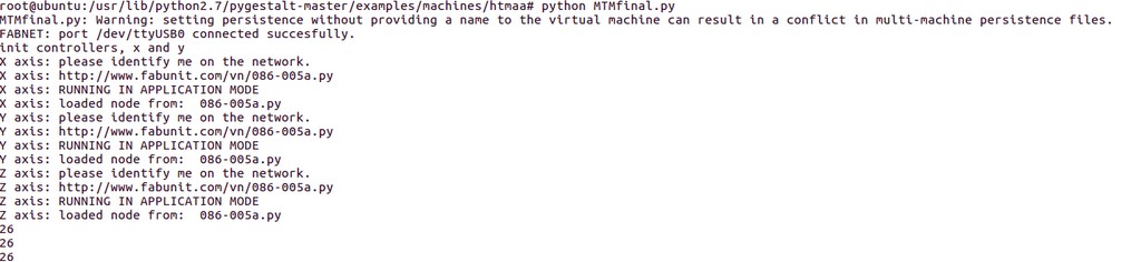
As we our machine will need to work with three axis movement, naturally I move on to the testing by running the following command in ubuntu.
Connecting the MTM Kit and Test Run on the Axis
Our MTM Kit consist of the folllowing
- 2 Stages - Stepper and roll bar
- 4 guide bars
- 3 gestalt circuit board
- 3 Ribbon Communicating Cables
- USB FTDI Cable
- Power supply


Using Nadya's hbotplusz.py as reference, we study the program code for the important function and also modify to suit our machine in python.
- Import the Gestalt library
   from pygestalt import nodes
   from pygestalt import interfaces
   from pygestalt import machines
   from pygestalt import functions
   from pygestalt.machines import elements
   from pygestalt.machines import kinematics
   from pygestalt.machines import state
   from pygestalt.utilities import notice
   from pygestalt.publish import rpc #remote procedure call dispatcher
   import time
   import io
    #------VIRTUAL MACHINE------
    class virtualMachine(machines.virtualMachine):  #eventually will subclass from gestalt
    def initInterfaces(self):
    if self.providedInterface: self.fabnet = self.providedInterface   #providedInterface is defined in the virtualMachine class.
    else: self.fabnet = interfaces.gestaltInterface('FABNET', interfaces.serialInterface(baudRate = 115200, interfaceType = 'ftdi', portName = 'COM10'))
    def initControllers(self):
    print "init controllers, x and y"
    self.xAxisNode = nodes.networkedGestaltNode('X axis', self.fabnet, filename = '086-005a.py', persistence = self.persistence)
    self.yAxisNode = nodes.networkedGestaltNode('Y axis', self.fabnet, filename = '086-005a.py', persistence = self.persistence)
    self.zAxisNode = nodes.networkedGestaltNode('Z axis', self.fabnet, filename = '086-005a.py', persistence = self.persistence)

    self.xyzNode = nodes.compoundNode(self.xAxisNode, self.yAxisNode, self.zAxisNode)
self.position = state.coordinate(['mm','mm','mm']) #X,Y,Z
    def initKinematics(self):
    # drive components of h-bot. Inputs are A/B stepper motors, outputs are X/Y in machine coordinates.
    # elements.elementChain.forward(
    # microstep => input microstepcount -> 1/microstepCount -> steps
    # stepper =>   input stepAngle (degrees) -> stepAngle/360 -> revolutions
    # pulley =>    input pitchDiameter (mm)
    # invert =>    if it is inputted backwards. false = its correct connection])

    self.xAxis = elements.elementChain.forward([elements.microstep.forward(4), elements.stepper.forward(1.8), elements.leadscrew.forward(8), elements.invert.forward(False)])

    self.yAxis = elements.elementChain.forward([elements.microstep.forward(4), elements.stepper.forward(1.8), elements.leadscrew.forward(8), elements.invert.forward(True)])
    self.zAxis = elements.elementChain.forward([elements.microstep.forward(4), elements.stepper.forward(1.8), elements.leadscrew.forward(8), elements.invert.forward(True)])

    self.stageKinematics = kinematics.direct(3)
    def initFunctions(self):
    self.move = functions.move(virtualMachine = self, virtualNode = self.xyzNode, axes = [self.xAxis, self.yAxis, self.zAxis], kinematics = self.stageKinematics, machinePosition = self.position,planner = 'null')
    self.jog = functions.jog(self.move) #an incremental wrapper for the move function
    pass
Drawing and test out the machine
I began the test with a simple square.
A square
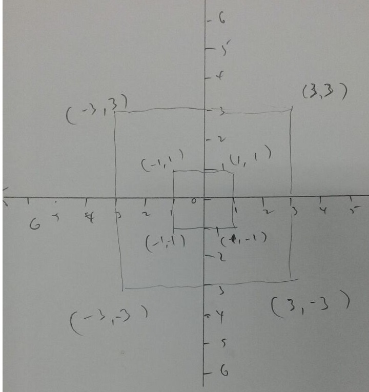
After our machine succesfully plotted a simple square I decided to test out the pen lifting capability, to draw a square within a bigger square. First up, I have to sketch the coordinates for a square within a bigger square on paper, calculate the coordinate for the design and then multiply accordingly to be used in the python code as it was mm.
Two Squares Drawing
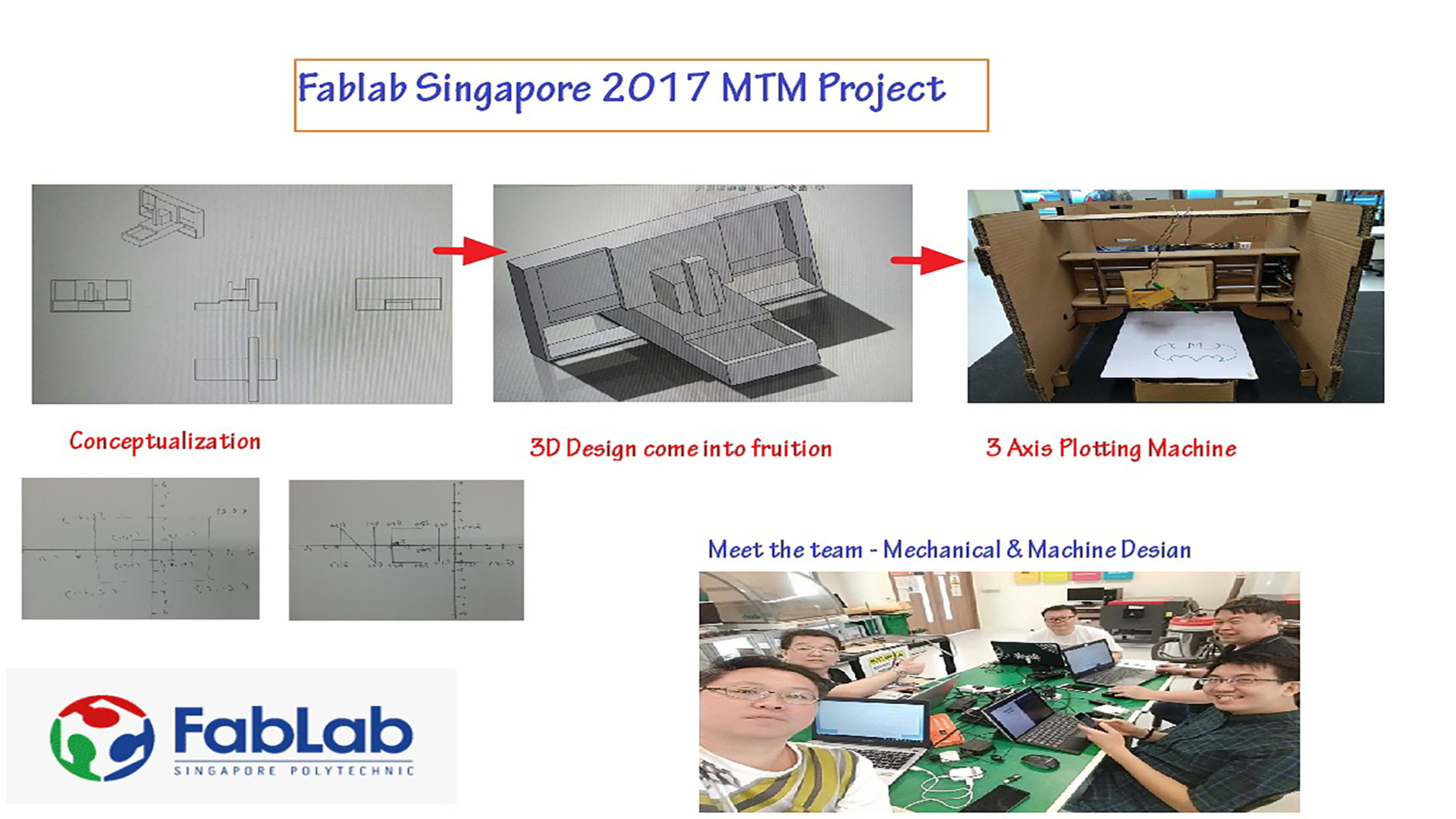
Website Documentation - Poster Design
While taking photo for most of our activities during the group discussion, I was also taking some short video clips that was later being edited by Louis into our presentation video as shown in our mtm group page. While at the same time, I had design the MTM page presentation slide and saved into poster.png file as shown in the snapshot below.