Week 3 - Computer controlled cutting
Intruduction
Third week was all about cutting stuff out of different materials using vinyl cutter and laser cutter. For vinyl cutter you will need a vector image. For the laser a vector image was needed as well but the design had to be done with a program that you could make a parametric design with. In my case I used FreeCAD software to make the parametric design. Then exported it in 2D form and used Inskape to make the final cut file for the laser.
Tasks for the week:
1. Make parametric design with CAD-software
2. Create a cut file from CAD design for the laser cutter
3. Cut the design with the laser cutter
4. Make a vector outline file for the vinyl cutter
5. Cut the design with vinyl cutter
Here are the manufacturing files of this weeks assingments:
Inskape .svg file of the dog
Parametric design FreeCAD-file
Parametric design .pdf file for cutter
Vinyl Cutter
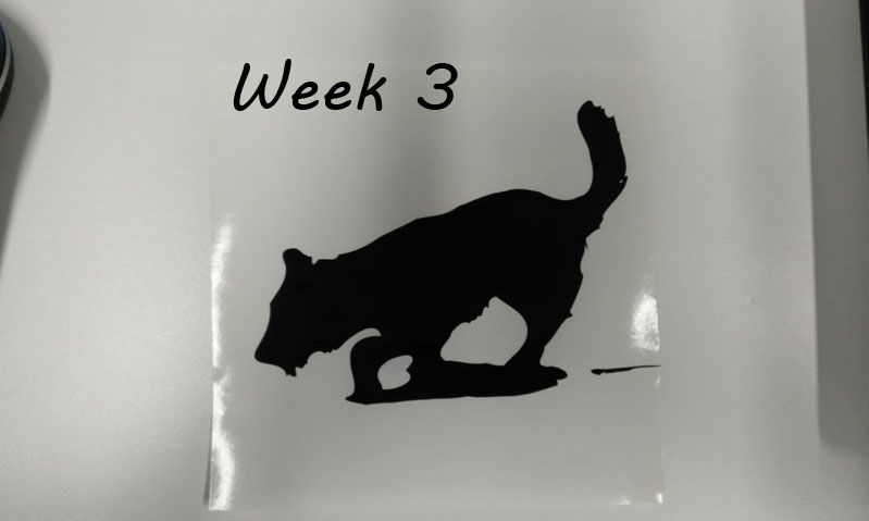
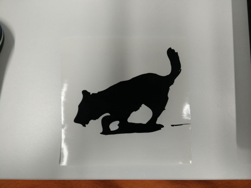
For vinyl cutter I chose to take some pictures of our dogs and make stickers out of them. The final goal is to get full size prints that will be put to the cars side for decoration. For the weekly assingment thought I managed to make small samples. Here is the processing.
General workflow was:
1. Get a good picture
2. Photoshop it to maximize side profile and convert to black and white
3. Import to Inskape
4. In inskape the outline vector is generated and all other data discarded
5. Finally the cut data is send to the vinyl cutter for cutting.
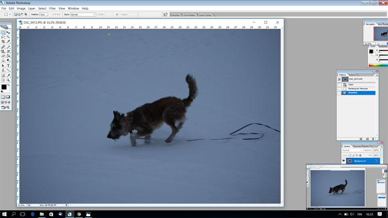
When starting the process I found out that I did not have any good contrast pictures I could get the outline from. So I had to get my camera and go out to take some pictures. Weather conditions did not support my idea but here is the picture good enough to start the process.
Photoshopping a picture is a process on its own and as it is not a part of weekly assingment I just list some processes I do with Photoshop:
1. Cutting the extra picture out using select->image->crop
2. Edit color distribution by image->adjust->levels and curves
3. Make image grayscale image->mode->grayscale
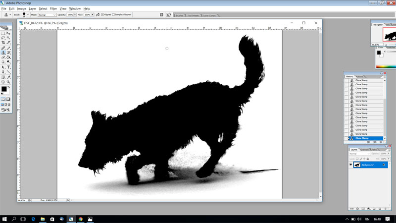
4. Make grayscale into black and white mode->adjustments->brightness/contrast
And here is the result.
I save the picture as .jpg and import it to Inkskape.
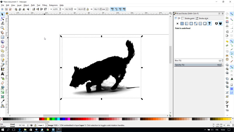
In Inkskape, first we have to get the outline of the image. This happens as follows:
1. Select the picture using "select and transform objects"-tool.
2. Use Path->Trace bitmap. Just use the basic setting, the result can be seen in advance if you click the preview-box as selected.
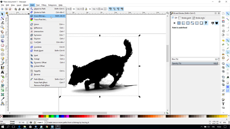
This process creates an new image on a layer that is below the first one. The original must be moved out of the way by selecting it and dragging it out of the way.
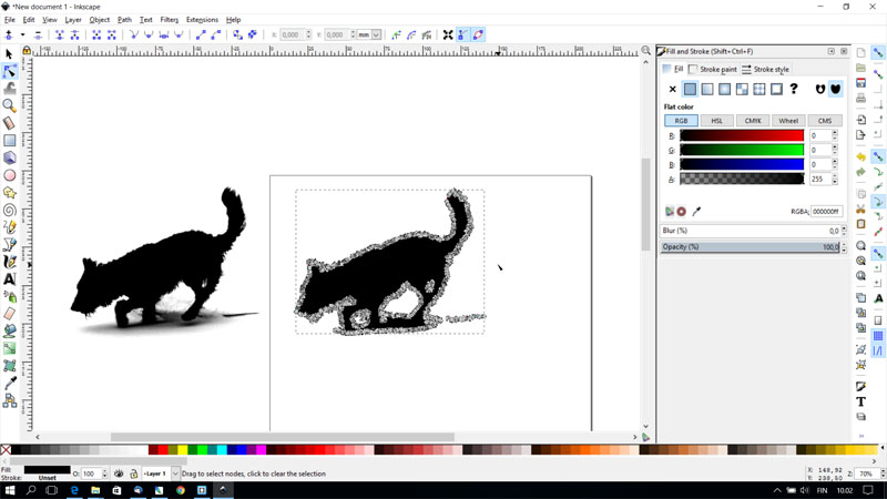
Now you have the outline vector there. It is quite complex, and it is a good idea to simplify it a bit. This happens by:
3. Path -> simplify. I did it couple of times to get rid of extra vertor points.

After 2 simplify rounds, it looks much better, but there still is some extra vertor points that are not usefull. To get rid of those, I just zoom in and select the points by hand and delete them.

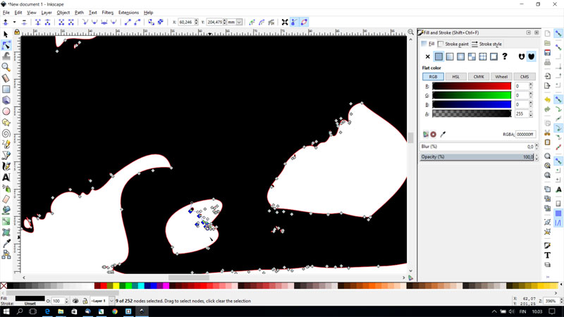
Here is the final version with only few vector points on the outline.
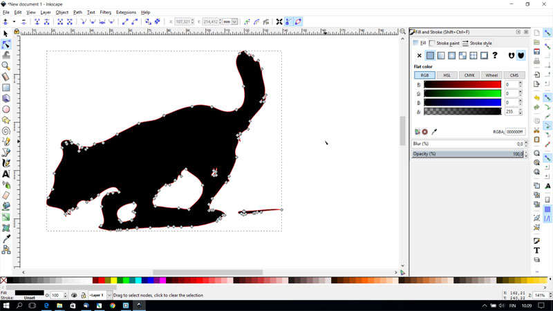
After this process, we have to separate the outline. This is done by:
4. select picture, activate "fill and stroke" window from Object->directory.
5. In fill and stroke window tabs, use:
6. Fill: no fill, stroke/paint: black, stroke style: width: 0,5pt.

The printing happens from Inskape, so the Inskape.svg is acceptable file form. It is important to put the picture to left bottom corner of the document so the printer dont use unnecessary material.
Setting up the vinyl cutter
To print with the vinyl printer at the fablab, some basic setting must be done to make the cutter ready. Setting the vinyl cutter up is as follows:
1. Turn the power on
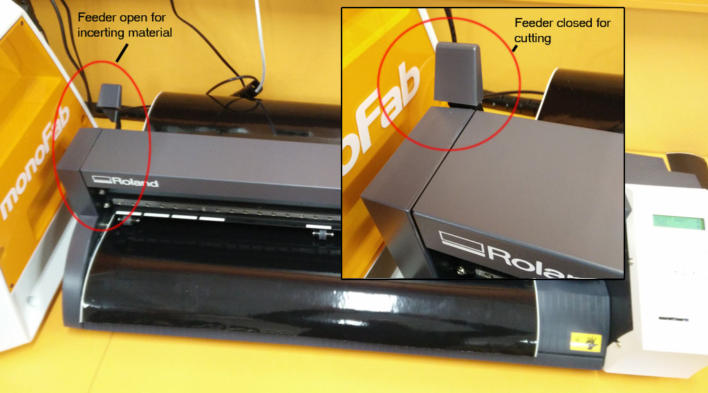
2. Put the material you want to the printer, we used sticker from the roll.
3. Push the lever down (backwards) to open the rollers. Insert material between rollers. Pull material far enought and align left side next to lines on the roller. Pull the lever back to the original position.
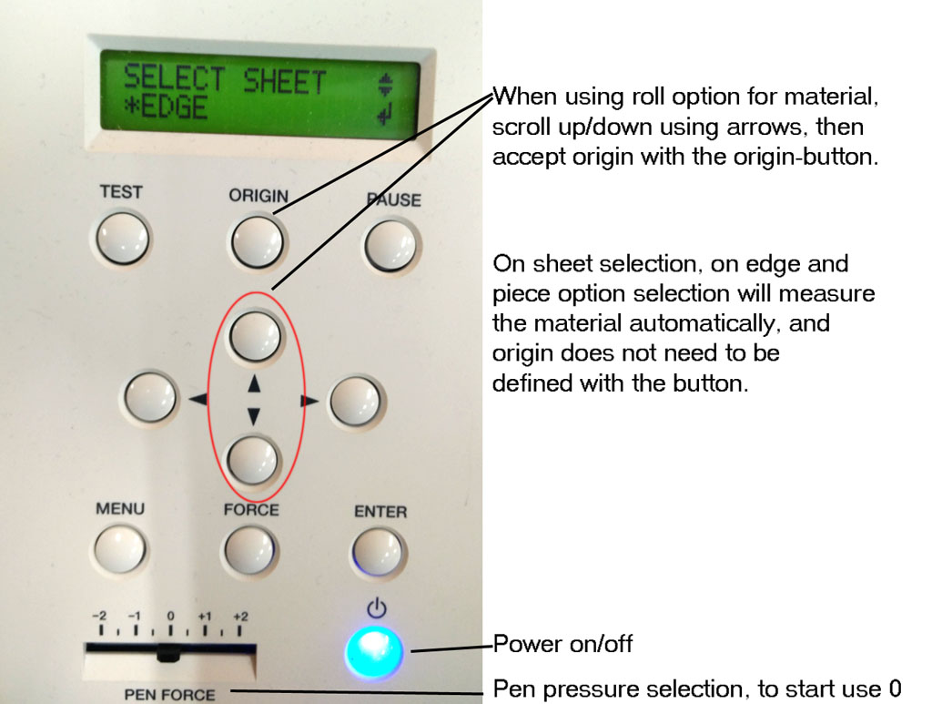
4. From controls, up and down buttons, select "edge" and press enter to accept. The cutter will find the edge of the laminate roll. Now the cutter is set.
4.1. There are 3 options here, roll, edge and piece. When selecting using material from roll, edge or roll can be selected. Edge option finds material edge for you, on roll option, material edge has to be found using the arrow keys, just run the material up as long as the cutter head finds the edge. Then press the Origin button. If using piece, the machine will measure the material dimensions for you.
5. From computer -> Inkscape make sure that the picture you are about to print fits defined document size. If not change the setting from File->Document Properties.
6. Make sure that the picture is in left bottom corner of the document.
7. Select Print and correct laminator as Printer, ours is Roland GS-24. Go to Preferences.
8. From Printing Preferences -> cutting area, select "Get from machine" This will set the width to correct value. Then select the length to same value as in Document Properties values.
9. Then you are done, just hit Print.
Parametric design and laser cutting
First thing to do is to make a part design in some suitable software. I started using FreeCAD and even thought it had some issues here and there I managed to make a parametric design and export 2D profile out of it to be edited in Inskape. In Inskape the final tuning of the design cut picture was made and finally saved as .pdf with linewidth of 0,02mm. Cutting with our lasercutter happened by printing to the cutter from .pdf file.
In FreeCAD I used sketch workbench to sketch the part. Biggest problem was to get the constraining done so that when modifying the parameters, the whole part kept its shape. First I did the constraining quite a hard way, defining most of the part sides one by one. But later learned from a co-student to use the equality constraint. That made life a much more easy.
Here is a picture of constraining. One on the right has all the sides constrained separately, on the left I have used equality constrain command to define all sides as equal. That makes it also really easy to use parametric defining of dimensions as there is only few variables to work with. On the left picture only four variables exist. Those are the ones with numeric definitions.
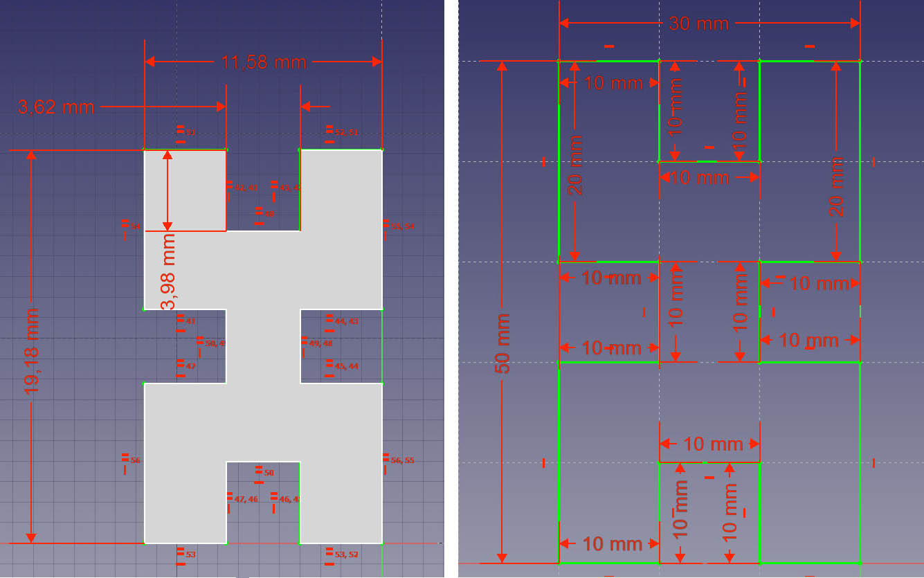
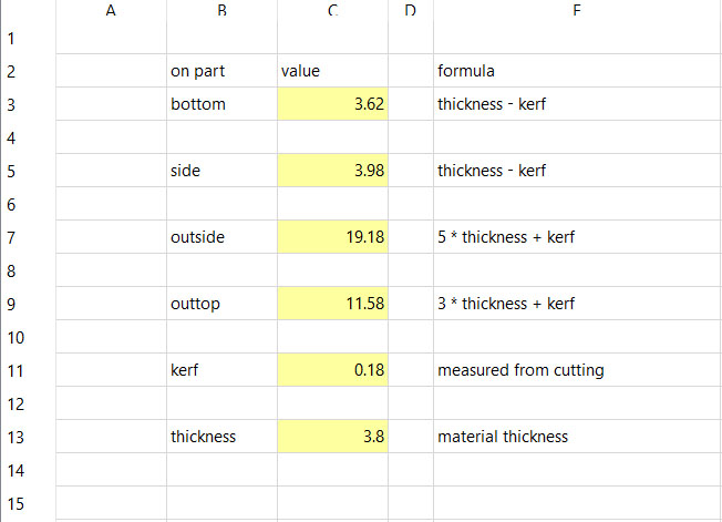
After sketching the part and constraining it. I used spreadsheet workbench to create "a document" where I could define all the dimensions of the part so that at the end, I just needed to define material thickness and kerf values, and all others were modified automatically. Here is the spreadsheet where the values are defined. All other values are calculated from material thickness and kerf values. On the right side next to values I have written open the formula I used to calculate dimensional values.
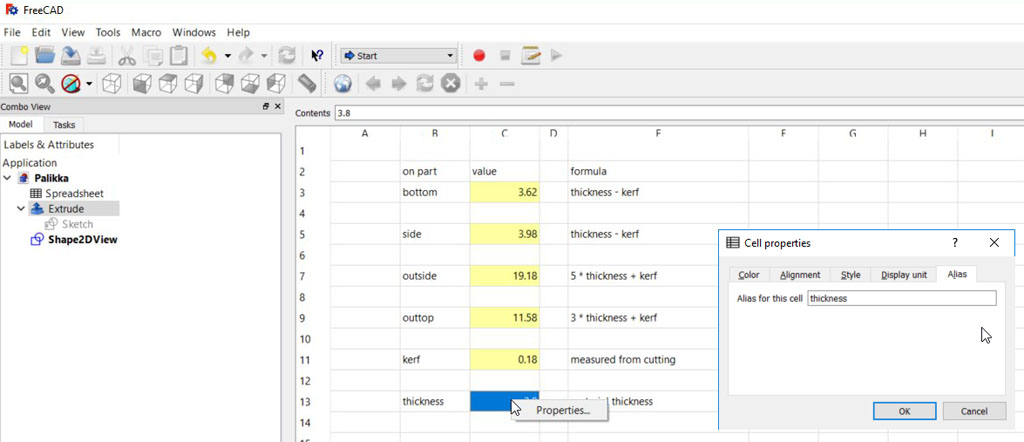
To connect the sketch with parameters in spreatsheet. This is done using aliases. This happen by going to spreadsheet, left clinking the value cell and selecting properties. From opening Cell properties, Alias tab is selected and alias is written in "Alias for this cell".
Next parametric values need to be linked to constrains in the sketch. Back in the Sketch view, Sketch Constraints every constraint need to be connected to the Spreadsheet alias. Clicking the constraint and then clinking the "fx" symbol, the spreadsheet value can be connected to the constraint. Connecting avery constraint to the spreadsheet alias I get parametrized design.

Finally after defining the part I wanted to cut with the laser, I first used Drawign workbench to get the 2D projection of the part out in Flattened svg format that I could import to Inkskape for final preparation. Using this method, for some reason that did not come clear to me, in inkskape I had 3 separate edge lines on top of each other. Two of those had to be discarded or else the laser would cut the same part three times over. With some help from co-student I found out that using Draft workbench it was more easy to generate the needed 2D-projection.
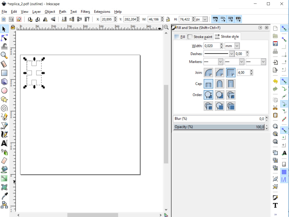
After exporting the flattened .svg-file, I opened it in Inkskape, defined the outline to be 0,02mm thick and positioned the part at the left top corner of the document. Now the document was ready to be saved as .pdf file for the laser cutter. You must also note that the line color is all black (256 value) and there is no opasity. If the printer does not find the line to be printed, check these values in Inkskape and create a new .pdf file.
Printing to the laser cutter happened from .pdf file. First open the .pdf, go to print file, where the laser must be selected as printer. Then correct material needs to be selected from list and loaded. If it is only outline cut, vector option has to be selected and finally just print to the laser.
Of course the laser cutter had to be set up. Put the right material in. Origo is on left top corner. Then the actual origo is defined by moving the laserhead to right position on top of material and accepted position. Then the focus must be set with the proper tool. After that, accept the print and go. At this point, if the print command is used at the computer, the file is visible at the printer screen, from it must be accepted.
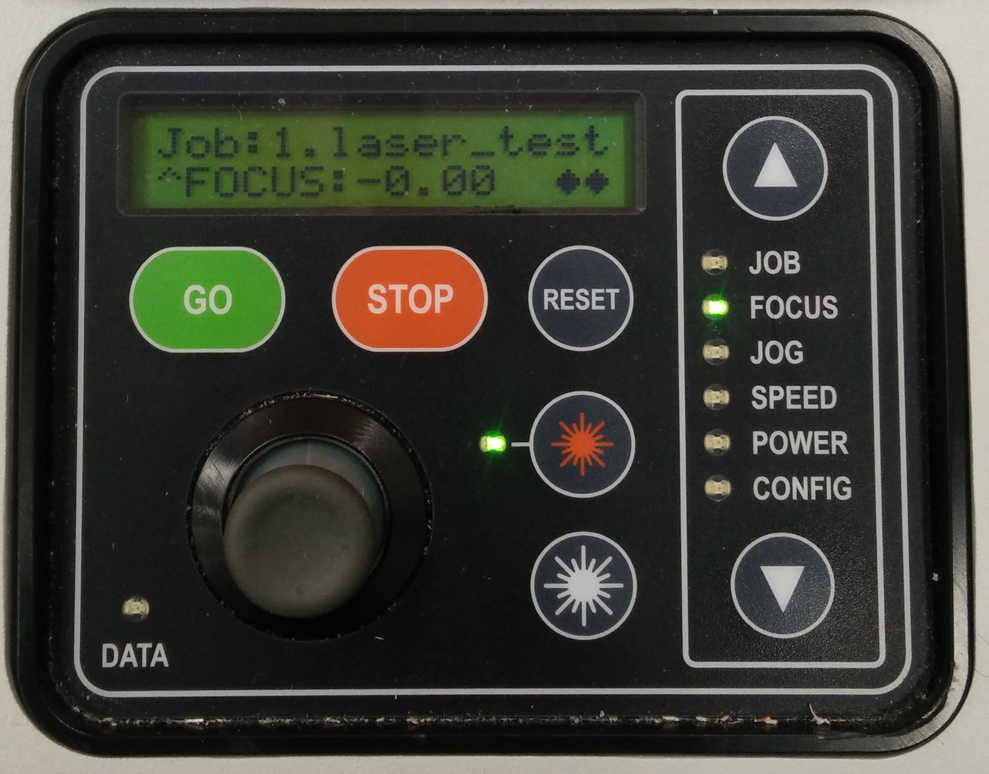
1.To set the origo, use up/down arrows to select JOG-option, then using the black joystick move the laser head in the position where you want the origo to be. Accept position by pushing the joystick down. This will set the origo. Laser head has a positioning pointing laser that can be activated from small red laser image next to a led. If the led is on, the pointing laser is on and it should be visible at the blank material. If you do not see it, you can use paper or something else to see the spot.
2. To set the focus, move selection to the FOCUS position (as is shown on the picture), take focus positioning triangle and position it to the laser head. Use up/down buttons to move the laser head up/down so that the head of the triangle just hit the blank material. Accept correct focus by pushing the joystick button.

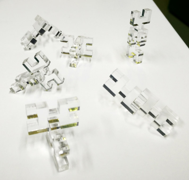
Here are some ready made blocks and some forms that can be build out of them. They are one type general blocks that can be assembled in multible ways.

Kerf and group assingment
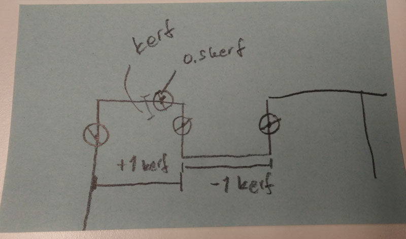
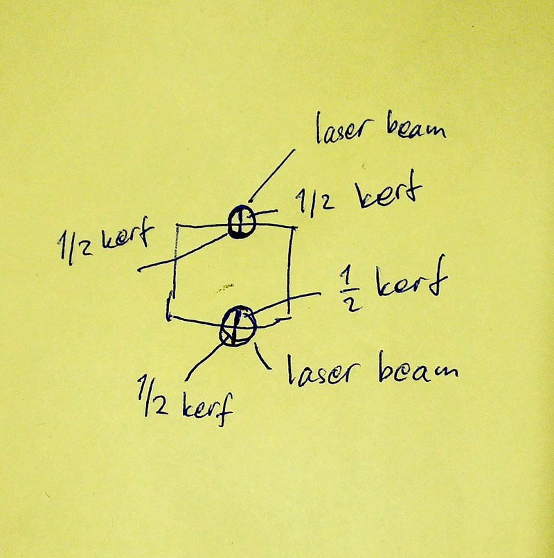
One of the biggest problems was to get my head around the kerf. At the end of the week I finally got the idea. Annoying problem was that the acryle material that I used for the test blocks was supposed to be 4 mm thick, but as found out later, on some points it was 4mm and on other parts of the blank it was 3.8mm. That made the optimal kerf finding a bit of a problem. Kerf is the width of the laser beam and at the same time the width that the beam will evaporate or rip of from the material. It depends on the setting of the laser as well as the properties of the laser cutting machine used. Here is some quite rude pictures of kerf as I was processing it. On the picture, as small circle is the laser spot on the line that it is cutting, depending on the parameters, the spot diameter varies, but as it is shown there, some material will be lost inside the line as well as outside the line. This needs to be considered while defining part dimensions. In this case some dimension had to be added to the outline cutting edge but at the same time some keft compensation had to be reduced from "pocket" part of the cut.
Group assingment
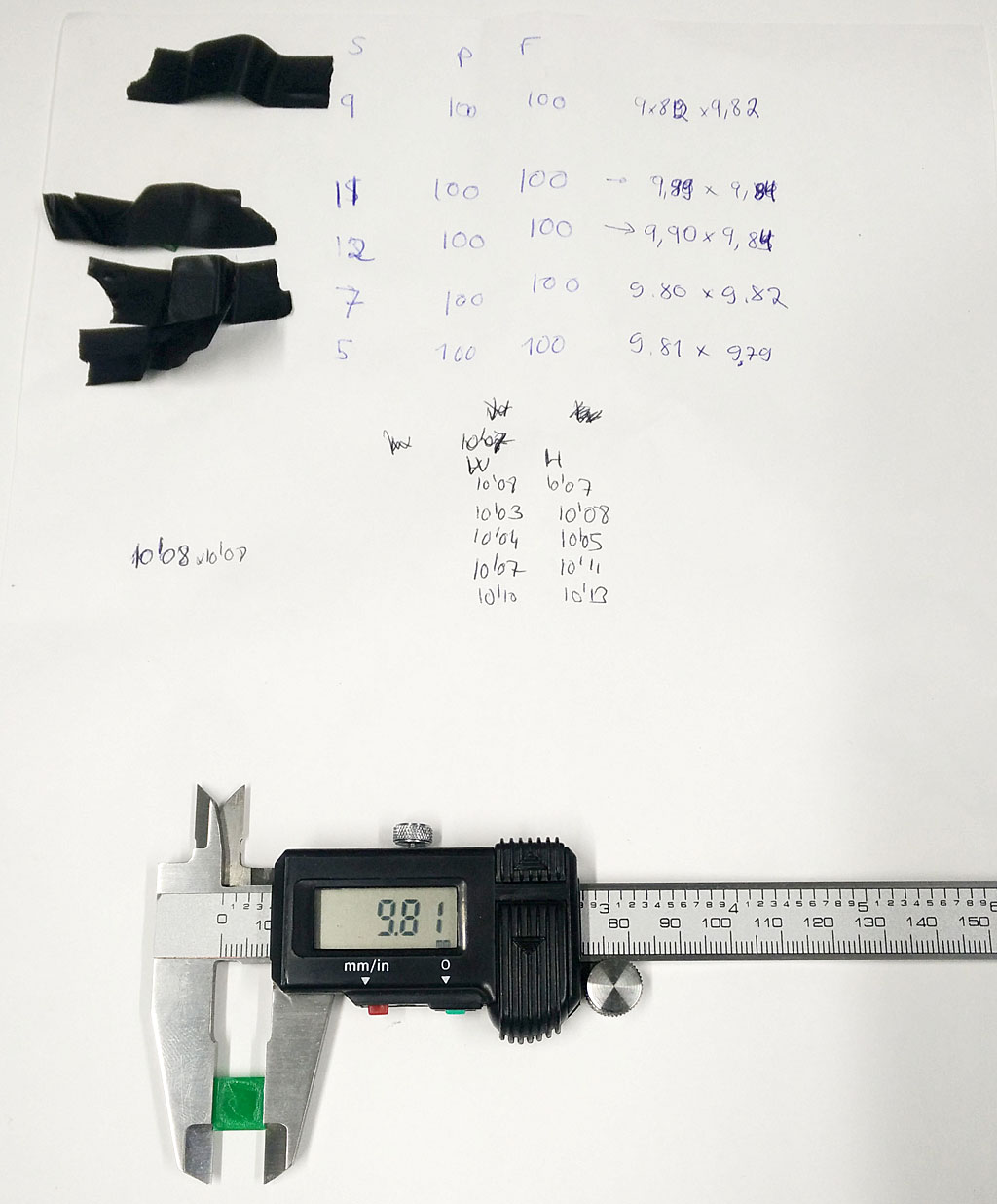
The group assingment was to define cutting values for the laser cutter at our FabLab. Our team consists of Ivan and Nataliya For the start, we cut some 1cm x 1 cm blocks out of 3mm acryl varying the cutting parameter speed to see what is the minumum value for fine cutting. From the blocks we measured lost dimension that gave us a look at the kerf values.
Cut block were measured using caliper. Measuring only the cut blocks, we get value of half kerf as cut line goes over the cut part and the "hole" that is left to the blank. To get the actual kerf value, you need to multiply the measured values from block. Thought if measured the whole lenght of the block, will give the actual kerf as half kerf is lost on both sides of the block.
Here is a table of values and results.
| Speed | Power | Frequency | Square Measures (mm) |
|---|---|---|---|
| 5 | 100 | 100 | 9.81 x 9.79 |
| 7 | 100 | 100 | 9.80 x 9.82 |
| 9 | 100 | 100 | 9.80 x 9.82 |
| 11 | 100 | 100 | 9.89 x 9.84 |
| 12 | 100 | 100 | 9.90 x 9.84 |
| 13 | 100 | 100 | Not cut |
| 15 | 100 | 100 | Not cut |
As from the table is seen when the speed was 13 or more, we could not cut through any more. So minimum value, keeping power and frequency at 100%, speed must be 12 or slower. From the dimensions it is also visible that with slow speed, material loss (kerf) gets bigger. From that and from tests done by our co-student Mikko we found out that the kerf is around 0.18 mm when cutting acryl around 3-4mm thick.
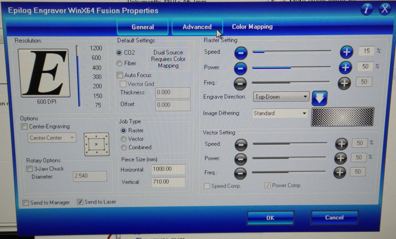
Here are pictures of laser settings for 3mm acryl cutting and some cuts that did not quite get through the blank material.