Object Design
In this second loop I decided to start by defining the design of the object better. I would like it to look like a pencil but on a larger scale, from a natural material like wood with some pieces printed in 3d or acrylic with laser cut.
I chose to generate an object with a well defined outer shape and then empty it inside to accommodate all the components.
I also want it to be able to be milled in the router on a board of thickness less than 3cms. So, the final design consists of two symmetrical pieces that come together to form the pencil.
A little workshop work ..
In the following days I will continue making adjustments to the inner part of the mold to fit all the components like in a game of tetris.
Electronics and programming
In this loop I will try to integrate all the final components to the system:
ATTiny 44
microcontroller,
potentiometer to adjust the threshold value and regulate the behavior of the
solenoid,
phototransistor
mini board to read the data of luminosity,
button
to change state in the information display by the
ledbar
, battery and power switch.
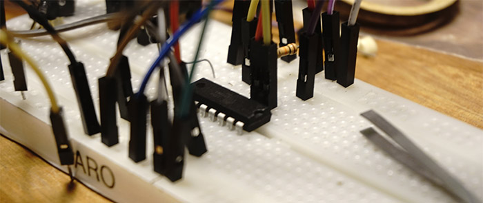
As in the first loop, I made the circuit by using a protoboard and an ATTiny84 microcontroller, similar to the ATTiny44 that I will use in my main board.
Here is the Arduino code i used for running the tests.
#include >Grove_LED_Bar.h>
Grove_LED_Bar bar(8, 9, 0);  // Clock pin (PWM pin) , (Digital) Data pin, Orientation

int potpin = A2;
int valuePot;
int valuePhotoMap;
int valuePhoto;
int solenoid = A7;

void setup() {
  pinMode(solenoid, OUTPUT);
  pinMode(valuePhoto, INPUT);

  bar.begin();
}

void loop() {
  valuePot = analogRead(potpin);    // reads the value of the potentiometer (value between 0 and 1023)
  valuePhoto = analogRead (A3);   // reads the value of the phototransistor (value between 0 (+light) and 1023 (-light))
  bar.setLevel(10 - (valuePhoto / 100));

  if (valuePhoto > valuePot) {
    analogWrite(solenoid, 127);
  } else {
    analogWrite(solenoid, 0);
  }
}
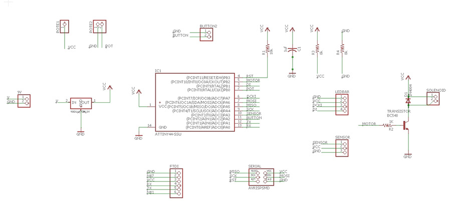
 The design of the circuit would then be as follows.
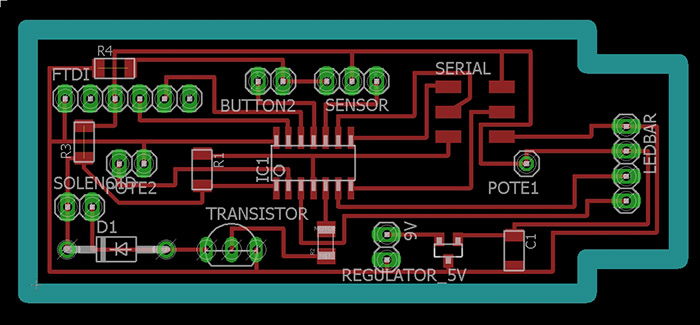 And here is the PCB to Gcode configuration for milling the board.
 The pcb milling and soldering process went fine. I use a BC548 transistor for connecting the solenoid and a LM3480IM3-5.0 linear voltage regulator for connecting the 9V battery.
Finally i added the button function to the main sketch and upload it to the ATTiny44.
The pcb milling and soldering process went fine. I use a BC548 transistor for connecting the solenoid and a LM3480IM3-5.0 linear voltage regulator for connecting the 9V battery.
Finally i added the button function to the main sketch and upload it to the ATTiny44.
#include >Grove_LED_Bar.h>
Grove_LED_Bar bar(7, 9, 0);  // Clock pin (PWM pin) , (Digital) Data pin, Orientation

int solenoid = 8;
int potpin = 10;
int valuePot;
int valuePhoto;

void setup() {

  pinMode(solenoid, OUTPUT);
  pinMode(valuePhoto, INPUT);

  bar.begin();
  buttonSetup();
}

int estado = 0;

void loop() {

  if (buttonLoop()) {
    estado = (estado + 1) % 3;      // changes program state
  }

  valuePot = analogRead(potpin);    // reads the value of the potentiometer (value between 0 and 1023)
  valuePhoto = analogRead (A3);   // reads the value of the phototransistor (value between 0 (+light) and 1023 (-light))

  switch (estado) {
    case 0:
      bar.setLevel(10 - (valuePhoto / 110));
      break;

    case 1:
      bar.setLevel(10 - (valuePot / 110));
      break;

    case 2:
      bar.setLevel(0);
      break;
  }

  if (valuePhoto > valuePot) {
    analogWrite(solenoid, 127);
  } else {
    analogWrite(solenoid, 0);
  }

}
And the button program.
// this constant won't change:
const int buttonPin = 2;

// Variables will change:
int lastButtonState = 0;     // previous state of the button


void buttonSetup() {
  pinMode(buttonPin, INPUT_PULLUP);
}


bool buttonLoop() {
    bool r = false;

    // read the pushbutton input pin:
    int buttonState = digitalRead(buttonPin);

    // compare the buttonState to its previous state
    if (buttonState != lastButtonState) {
      // if the state has changed, increment the counter
      if (buttonState == LOW) {
        // if the current state is HIGH then the button
        // wend from off to on:
        r = true;
      }
      // Delay a little bit to avoid bouncing
      delay(5);
    }
    // save the current state as the last state,
    //for next time through the loop
    lastButtonState = buttonState;

    return r;
 }
Assembly and testing
The process of assembling the components was quite difficult, there is really little space inside the pencil!
To achieve a good fit of the electronics inside the pencil I had to enlarge the interior cavity with hand tools.
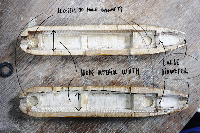 The recesses were supposed to go magnets to keep the parts together, but it was very difficult to make that type of closure work.
For some reason the battery has not worked yet, I think the voltage regulator may have overheate. I also had problems with the potentiometer, it seems not to work in the whole range, maybe because of its resistance value: 1K but i will recheck pin configuration.
In the next loop I will try to improve this issues.
The recesses were supposed to go magnets to keep the parts together, but it was very difficult to make that type of closure work.
For some reason the battery has not worked yet, I think the voltage regulator may have overheate. I also had problems with the potentiometer, it seems not to work in the whole range, maybe because of its resistance value: 1K but i will recheck pin configuration.
In the next loop I will try to improve this issues.
Here
is the link for download the files of this second loop.
Continue to third loop.