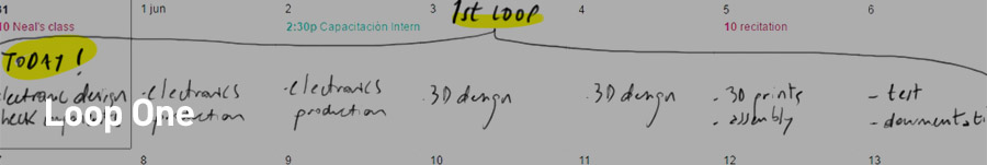
Electronics and programming
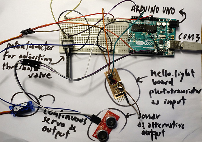
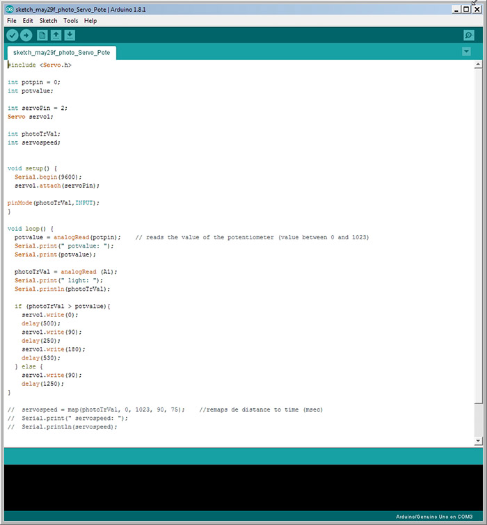
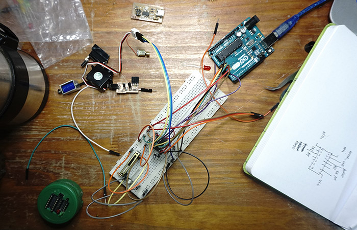
First, I want to focus on my weaknesses: electronics and programming. The first thing I did was quickly translate the ideas by assembling a circuit with an Arduino UNO, a protoboard, some sensors and test engines. This also allowed me to do a quick check of the programming by uploading a simple sketch for testing light/shadow response.
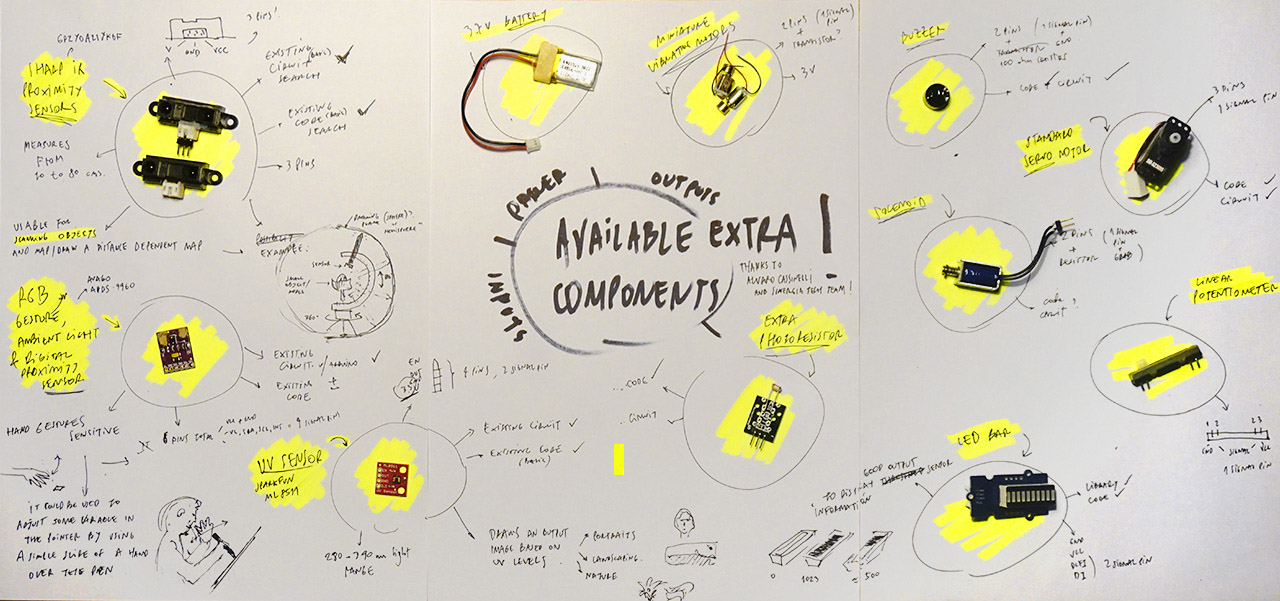
 After doing the tests of the circuit I received some new interesting components to play with more possibilities of inputs and outputs. Some of them are very useful for the project, such as the linear potentiometer, the ledbar, the IR proximity sensor and the RGB sensor, I will try to include them as alternative options in the design of the circuit in Eagle.
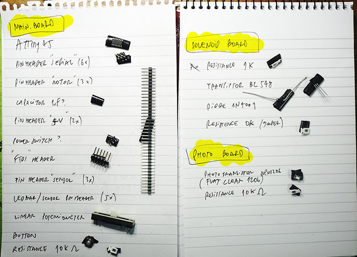
 I want the pen to be a modular system with fixed parts and interchangeable parts like pointers and sensors. So, I designed three different circuits in Eagle: the main circuit (with an ATTiny44 module), the input circuit with a phototransistor and the output circuit with a solenoid as the actuator.
 Later on I will realize that during the design I did not take some important variables of Attiny44 pinout into consideration and made several silly mistakes.
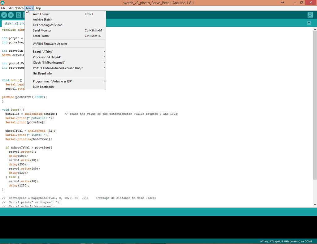
I tried to program the board several times through Arduino IDE, using an Arduino UNO as an ISP.
Later on I will realize that during the design I did not take some important variables of Attiny44 pinout into consideration and made several silly mistakes.
I tried to program the board several times through Arduino IDE, using an Arduino UNO as an ISP.
Despite checking the welds several times I could not get the operation done successfully :(
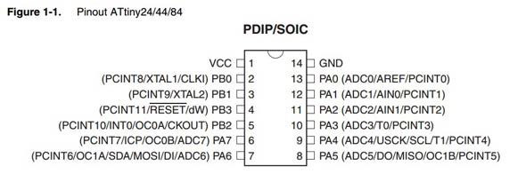
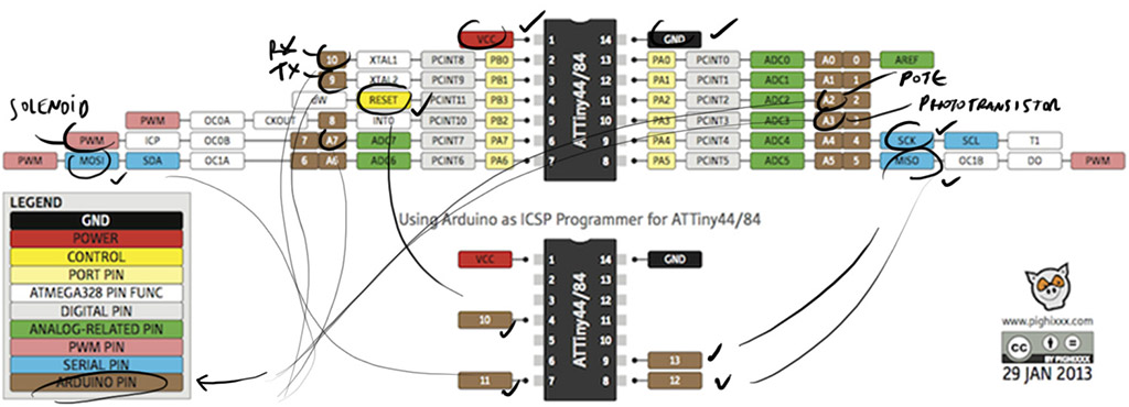
I decided to return to the protoboard but this time I got a ATtiny84 micro, similar to ATtiny44 but with more memory. Now I can test the programming directly from Arduino IDE avoiding, for the moment, possible interferences in the process due to errors in the design and electronic.
 It is always useful to have the ATtiny84 datasheet and the corresponding pins for programming in Arduino IDE.
 After a little programming in Arduino IDE I managed to get the solenoid to act by moving a pen, interpreting the light values in real time.
Here
is the link for download the files of this first loop.
Object Design
The first concept that I decided to explore at the formal level was the possible generation of a modular system that could contain independently the main board of the input sensors and the output actuators.
The idea is to generate small "tubes" of 5 cm in height that can be embedded between them and generate the general external shape of the pencil.
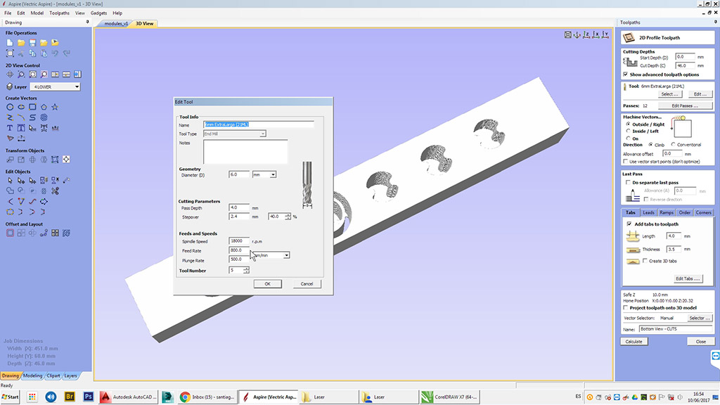
I worked the digital design with Autodesk Autocad and programmed the file for the ShopBot router in Vectric Aspire.
Because of the shape of its engagement the milling work must be done double sided.
As the material to be used is a hard wood I will use an extra long tool so we decided to reduce the fedd rate to 800 to avoid damages to both the milled parts and the tool itself.
 The results were not very good. The walls 3mm thick in some areas disappeared completely. Probably a precision error when placing the piece on the second side.
To fix the components inside the "generic" tubes, design and print some specific 3d parts for each component.
Although the results have not been entirely bad, for the next loop I will evaluate Neil's last class phrase "make almost anything" instead of "make almost everything" in order to concentrate my energy ant time in a more concrete finished object rather than in a modular system.
Here
is the link for download the files of this first loop
Continue to second loop.