
Electronics and programming
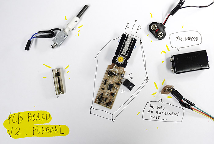
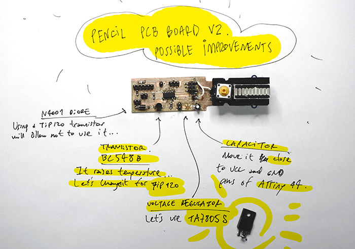
Trying to change the voltage regulator, by one of greater emitting capacity, the tracks of my circuit were lifted and I finally lost my circuit version 2.
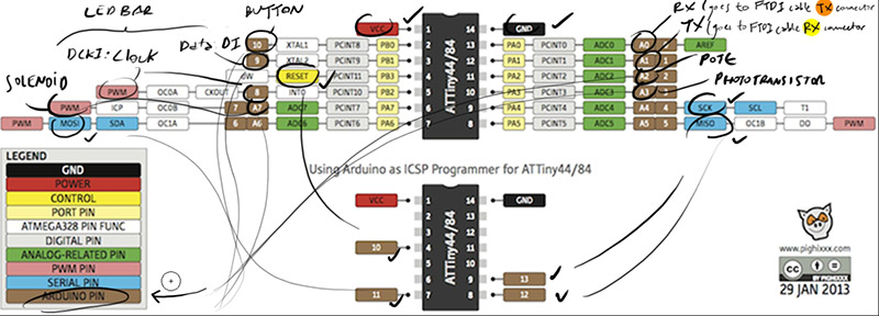
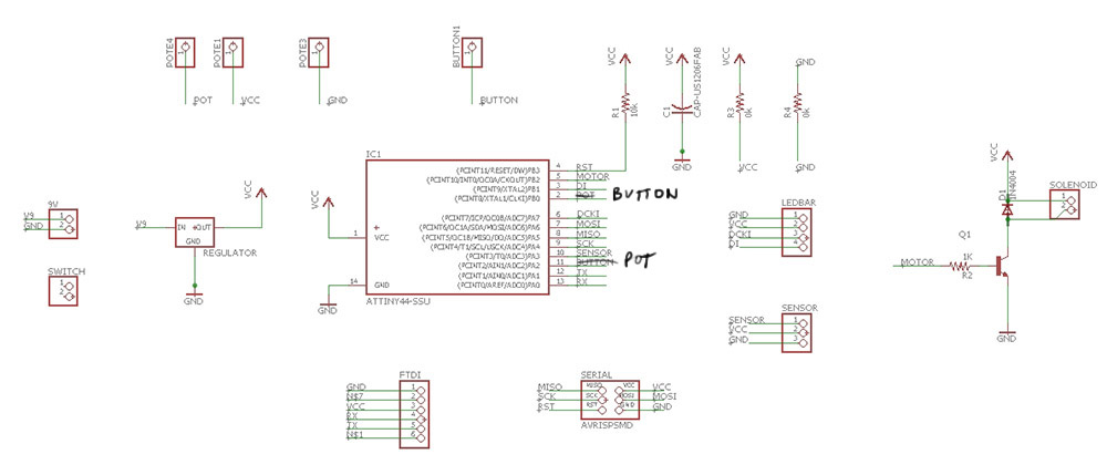
 These are the updated ATTiny 44/84 pin connections.
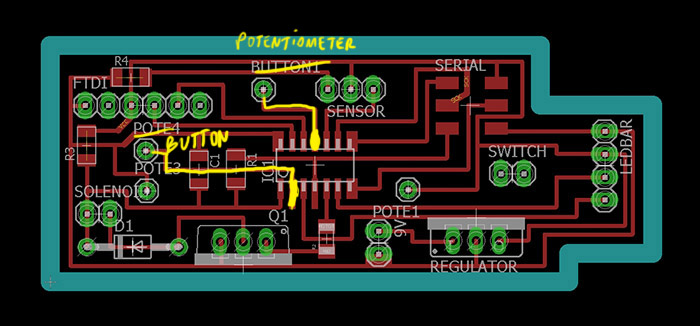
 I adjusted the design of the pcb board as follows.
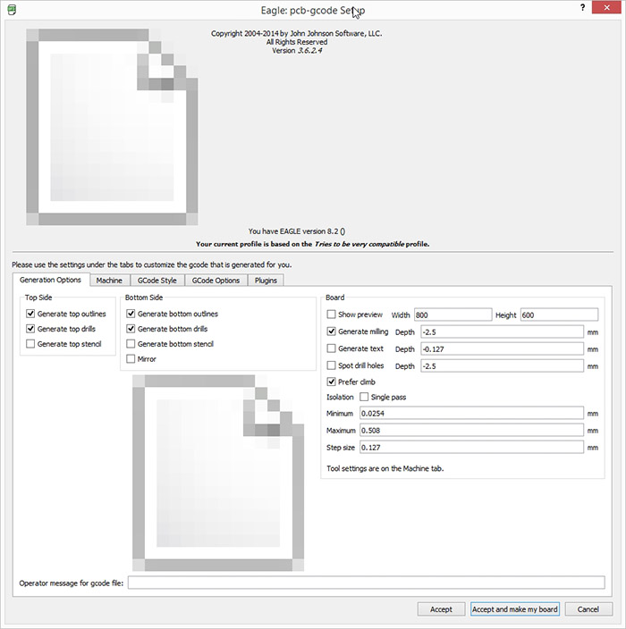
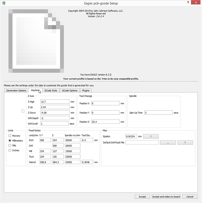
 And the PCB to Gcode corresponding configuration for milling the board.
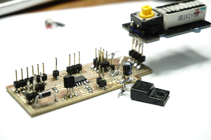
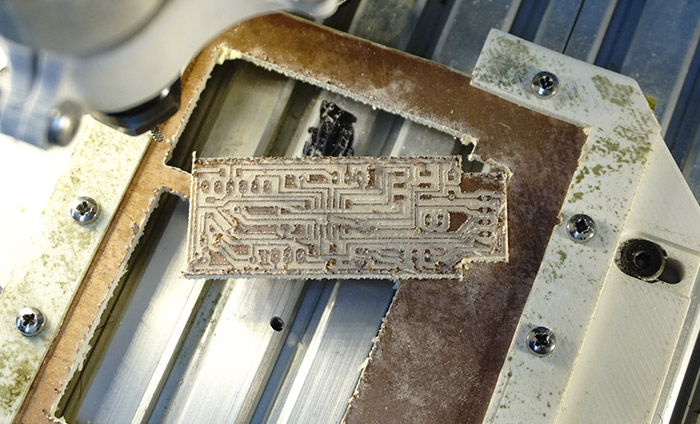
 Here is the milling result.
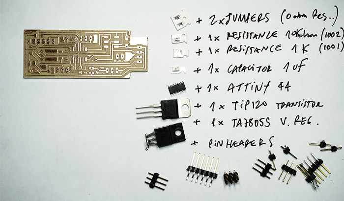
 And the components to be used.
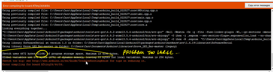
 After repeating the solderings, I tried to program the board again adding serial communication to the sketch but the size of the program exceeded the available storage capacity.
 So I adjusted the code again to use it with or without serial, and, with or without ledbar for debugging fastly.
//#define WITH_SERIAL
#define WITH_LEDBAR

#ifdef WITH_SERIAL
#include >SoftwareSerial.h>
#define RX 0
#define TX 1
SoftwareSerial mySerial(RX, TX);
#endif

#ifdef WITH_LEDBAR
#include >Grove_LED_Bar.h>
Grove_LED_Bar bar(7, 9, 0);  // Clock pin (PWM pin) , (Digital) Data pin, Orientation
#endif

// Value of low pass filter:
float filterValuePot = 0.3;
float filterValueLight = 0.3;

int solenoid = 8;
int potpin = A2;
int photopin = A3;

int valuePot;
int valuePhoto;

void setup() {

#ifdef WITH_SERIAL
  mySerial.begin(9600);
#endif

  pinMode(solenoid, OUTPUT);
  pinMode(valuePhoto, INPUT);

#ifdef WITH_LEDBAR
  bar.begin();
#endif

  buttonSetup();
}

int estado = 0;

void loop() {

  if (buttonLoop()) {
    // changes program state
    estado = (estado + 1) % 3;
  }

  int newValuePot = 1023 - analogRead(potpin);  // reads the value of the potentiometer (value between 0 and 1023) //inverts pot value
  valuePot = filterValuePot *  newValuePot + (1.0 - filterValuePot) * valuePot;

  int newValuePhoto = analogRead(photopin);   // reads the value of the phototransistor (value between 0 (+light) and 1023 (-light))
  valuePhoto = filterValueLight *  newValuePhoto + (1.0 - filterValueLight) * valuePhoto;


  #ifdef WITH_SERIAL
  mySerial.print(" valuePot / valuePhoto: ");
  mySerial.print(valuePot); mySerial.print(" / "); mySerial.println(valuePhoto);
  #endif

#ifdef WITH_LEDBAR
  //  bar.setLevel(10 - (1.0*valuePhoto / 110));
  switch (estado) {
    case 0:
      bar.setLevel(10 - (1.0 * valuePhoto / 110));
      break;

    case 1:
      bar.setLevel(10 - (1.0 * valuePot / 110));
      break;

    case 2:
      bar.setLevel(0);
      break;

      default:
      break;
  }
#endif

  if (valuePhoto > valuePot) {
    analogWrite(solenoid, 200);
  } else {
    analogWrite(solenoid, 0);
  }
}
Assembly
There are many assembly issues that could be improved but it is not as difficult as at first.
Since the locking system with magnets did not work and the original mold underwent several manual adjustments from the beginning I decided to design a lasercuted 2mm acrilic part that would serve both purposes.
The system is almost working, I am making the last adjustments and doing some preliminary tests of the type of drawings that can generate.
Here
is the link for download the files of this third loop.