Assignment
* Design and build a wired &/or wireless network connecting at least two processors
Neil's class Summary
Design
For this week assinment I chose to do the asynchronous serial communication board.
I designed my circuits at Eagle, following Neil's board and consulting some documentation from previous years made by
Carolina Vignoli and Gabriel Tanner.
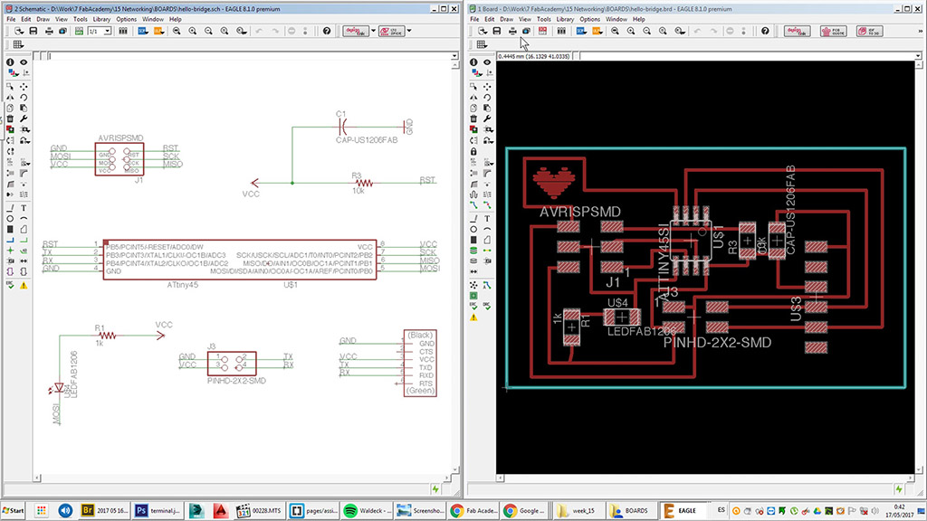
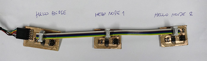
These are the results of the schematic view and board view for the hello.bus.45.bridge board.
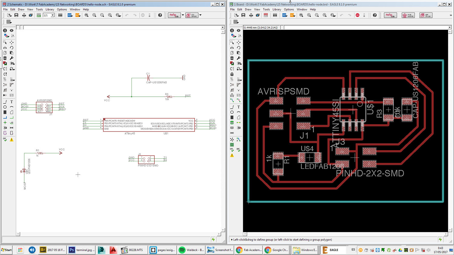
 And here the ones for the hello.bus.45.node boards.
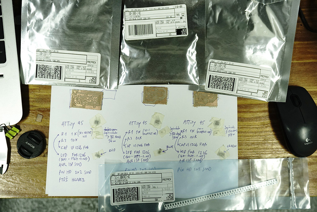
 I decided to use led lights of three different colors to distinguish the circuits: red for bridge, blue for node # 1 and green for node # 2.
With the values of voltage and current taken from the technical sheets of led lights, I used this
online application
to calculate the required resistance for each color. So the results are ..
LED RED CLEAR 1206 SMD for the hello.bus.45.bridge board.
 LED BLUE CLEAR 1206 SMD for the the hello.bus.45.node#1 board.
 LED GREEN CLEAR 1206 SMD for the the hello.bus.45.node#2 board.
 Finally I decided to use resistances of 1k ohm for all leds since it exceeded the necessary value.
Download the EAGLE files.
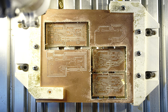
Fabrication
After milling the circuits in our local "Gava Milling Machine", I ordered the necessary components for each boarf and then solder them.
Programming
The programming was quite simple since the milling and the welds were very well executed -Thanks Mer for your hands and nails :-)
For the programming of the boards I started by downloading the files hello.bus.45.c and the makefile of Neil.
Then I copied the same content to three different folders, each folder will contain the same pair of files but we will make different editions according to each board in each C file.
 This is a brief interpretation of the basic C code for the serial bus asynchronous communication written by Neil that I will run on each node.
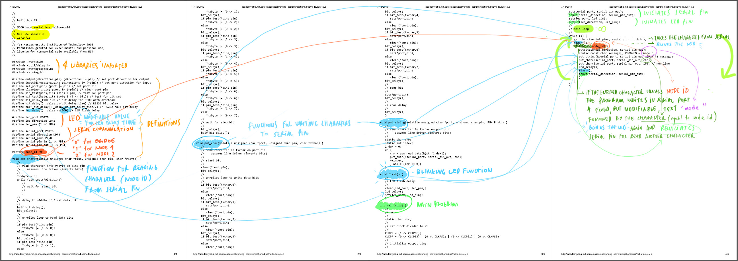 I edited C file line #29, adding some more ms for led delay time
#define led_delay() _delay_ms(1000) // LED flash delay
and line #220, for the display the message "hello node " previous to node id number.
static const char message[] PROGMEM = "hello node ";
Then I edited line #41 (the id of each device) in each C file of each folder (corresponding to each board) #define node_id
'0' for bridge, #define node_id '1' for node 1, #define node_id '2' for node 2.
 I used my FabISP board to independently program the bridge and the nodes. These are the connections for each board.
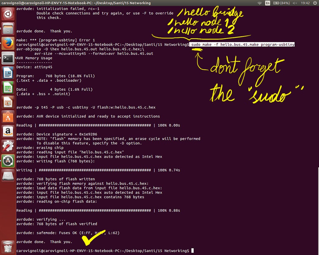
 Now from Terminal, I navigated to each folder and ran the corresponding makefile for each board. This is the sentence:
sudo make -f hello.bus.45.make program-usbtiny
These are the final connections to run the tests.
 Finally in Arduino IDE I configured the board as ATTiny 45, the clock as "Internal 8 Mhz" and port as "/dev/ttyUSB0".
Now using the Serial Monitor, the led light should blink twice by sending "2" for hello.bus.45.node#2 (green led board), sending "1" for hello.bus.45.node#1 (blue led board) and sending "0" for the hello.bus.45.bridge (red led board). Here a brief video of that test.
Download the programming files.