
Group assignment
* Automate your machine.
Neil's class Summary
Group website
Hardware installation
In this stage of work I will be responsible for gathering and operating the set of electronic components that the drawing machine will use.
We do not have the Gestalt Nodes and the FabNet board, so we decided to solve the problem using an Arduino UNO + CNC Shield and two Pololu stepper carrier drivers.
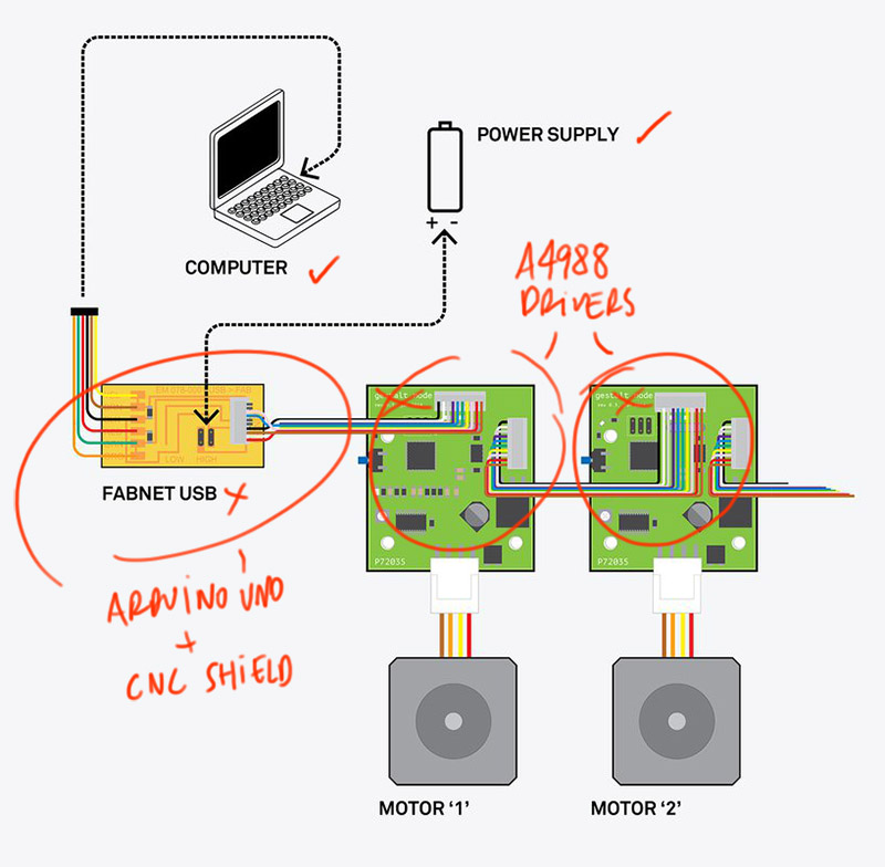
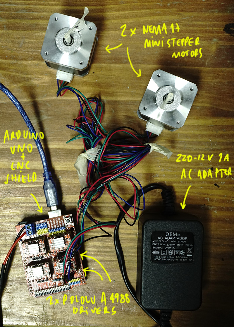
These are the electronic components to be used:
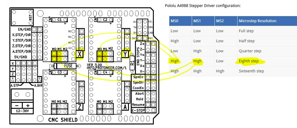
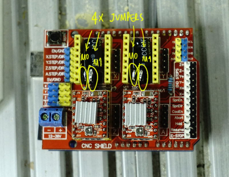
First, i connected the CNC Shield over the Arduino UNO and before connecting the A4988 stepper motor carrier drivers I studied the proper configuration of jumpers to obtain a 1/8 microsteps resolution.
 Then I connected the A4988 drivers and power to CNC Shield paying special attention to the correct orientation of +/- cables.
We managed to get a 220-12V, 1A AC adapter, let's hope that the intensity is enough to move both motors simultaneously. Otherwise, each A4988 controller has a power regulator that allows each motor to be calibrated separately.
This video was very helpful for me in the assembly process, and also this site.
Software installation
As we will be using
GRBL, a CNC controller software and g-code interpreter, running on an Arduino Uno board, the first step is install the corresponding library. Just copy the unzipped folder to ..\Arduino\libraries\ rename it to GRBL and restart Arduino IDE.
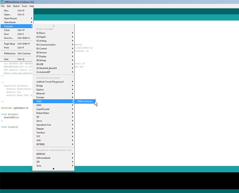
Connect the Arduino UNO board and upload the sketch found in File ->Examples –> GRBL (or what ever you renamed the folder to) -> GRBLtoArduino
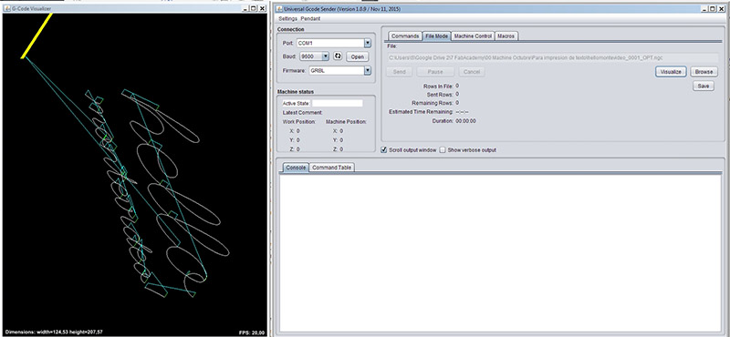
 There are several programs compatible with GRBL to send g-code to CNC machines. We find that Universal GcodeSender, a Java based GRBL compatible cross platform G-Code sender, has a lot of documentation, fits very well with the use of our machine and comes with a fast 3D g-code visualizer.
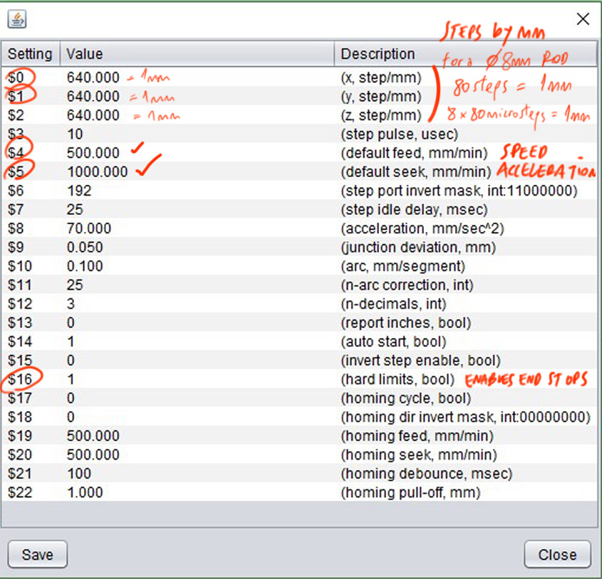
 It is necessary to set the movement parameters within the program. To do this, we use the "$$" command to display the parameters and "$ (parameter number) = (your value)" to set another value, as example "$ 5 = 1200" for setting feed rate to 1200 mm / min.
This video was very helpful for me in this part of the process.
 After a while of testing I managed to perform a test of the system.
System integration
The first thing to do was to integrate the new electronics into the frame on the X axis.
Then we concentrate on solving some mechanical problems in the frame and stage of the Y axis. We work both members of the group in simultaneous looking to improve the slippage of the stage and the union between the threaded rod and the stepper motor.
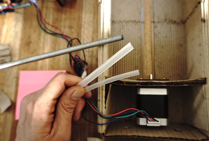
For the union of the rod and the stepper motor on Y axis we finally use a small rubber tube that holds both parts very well.
 Now we are ready to start drawing with gcode! Here is the first test of alignment and sliding.
And here is a video of the complete process.
Here
is the link for download the files of this week assignment.
Now we are ready to start drawing with gcode! Here is the first test of alignment and sliding.
And here is a video of the complete process.
Here
is the link for download the files of this week assignment.
Please visit our group website for more information.
Go back to week 9 assignment: Mechanical Design.