Procedure:
0. Assignment
1. The Board I have Used (board, LED RBG)
2 Checking the RGB Led Works Correctly
3. Processing
4. Communicating From The Computer To The Board
5. Communicating From The Board To The Computer
6. My Program - Further Investigation
7. Download Files
0. Assignment
Write an application that interfaces with an input and/or output device that you made, comparing as many tool options as possible.
LEARNING OUTCOMES
Interpret and implement design and programming protocols to create a Graphic User Interface (GUI).
HAVE YOU...
...described your process using words/images/screenshots
...explained the the GUI that you made and how you did it
...outlined problems and how you fixed them
...included original code
1. The Board I Have Used (Board, LED RGB)
For this week's assignment, my goal is to communicate with the computer with my board
which contains a RGB led. I will do that using processing and programming the board with arduino.
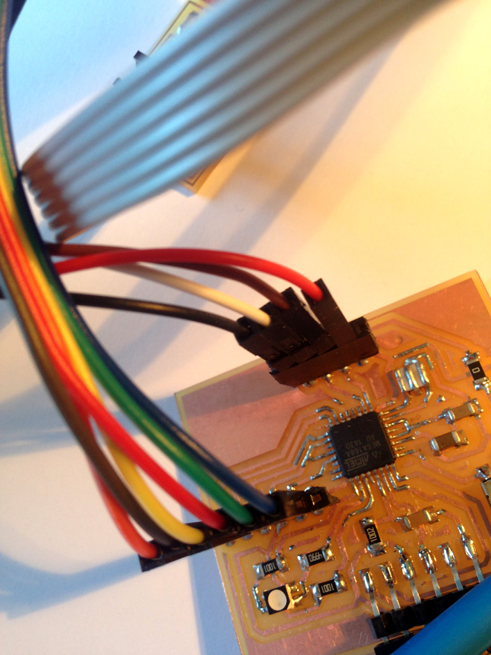
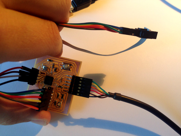
This is the board I have used is the same one as my Input's Assignment. Apart of building one for my sonar, I included
a RGB led:
For more info, go to Inputs:
In one hand, I want to communicate from the computer to the board and on the other, from the
board to the computer.
2. Checking The RGB Led Works Correctly
As during the fabacademy I have used individual leds for my Embedded Programming Academy, this
one I wanted to use a RGB led. As I did not know how to program it, I went on the internet and
found a good tutorial (https://fabricadigital.org/leccion/como-usar-un-led-rgb-con-arduino/ )(in
this case in Spanish), read it, and tried the sketch code example.
RGB Led With Common Anode
Analysing the RGB Led, now I know there are two types of RGB Led: the ones that have a common anode and the ones that a common cathode.
-Common Cathode:
the common cathode is connected to the ground and each individual Led is connected to a resistor. Then, the resistor is connected to the output pin.
-Common Anode:
the common anode is connected to the +5V and each individual Led to a resistor each. Then, connect that resistor to an output pin.
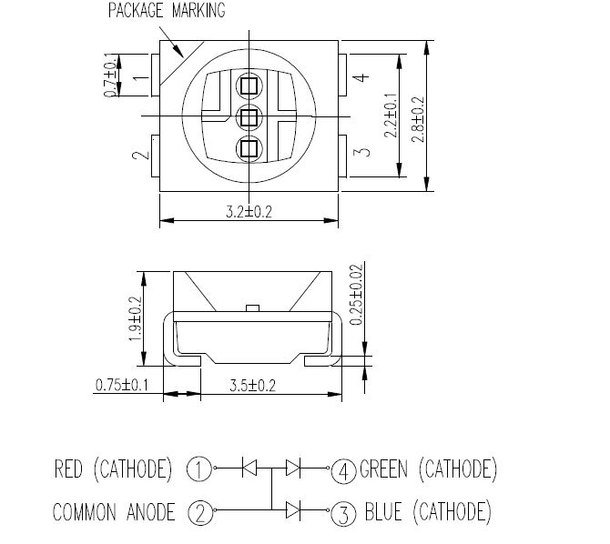
Just below there is the technical information of the RGB Led I am using:
The one I am using for this week is a RGB Led with a common Anode. Therefore, the led works with an inverse logic for coding. It should be difficult to think the other way round.
Explaining the Code
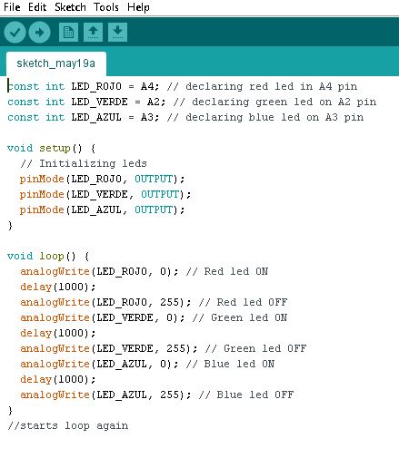
First I define the different variables for each pin (as they are constant variables, I declare them as such).
In my case, the red led is pin A4, the green led is A2 and the blue led is A3.
For the setup, I initialize each pin with the command 'pinMode'. First I start turning on the red led,
then use the command 'delay for 1000 milliseconds, turn of the red led and turn on the green led.
The same process to end with the blue led, starting the loop all over again.
				const int LED_ROJO = A4; // declaring red led in A4 pin
const int LED_VERDE = A2; // declaring green led on A2 pin
const int LED_AZUL = A3; // declaring blue led on A3 pin

void setup() {
  // Initializing leds
  pinMode(LED_ROJO, OUTPUT);
  pinMode(LED_VERDE, OUTPUT);
  pinMode(LED_AZUL, OUTPUT);
}

void loop() {
  analogWrite(LED_ROJO, 0); // Red led ON
  delay(1000);
  analogWrite(LED_ROJO, 255); // Red led OFF
  analogWrite(LED_VERDE, 0); // Green led ON
  delay(1000);
  analogWrite(LED_VERDE, 255); // Green led OFF
  analogWrite(LED_AZUL, 0); // Blue led ON
  delay(1000);
  analogWrite(LED_AZUL, 255); // Blue led OFF
}
//starts loop again
Commands used:
-pinMode (pin, mode): Configures a specific pin as an input, input_pullup or output. In this case, as an Output.
-analogWrite(pin, value) - using PWM: Writes an analog value to a pin. The value can vary between 0 (turned off) and 255, varying the led's brightness (in this case).
-delay(milliseconds): Pauses the program for the amount of time specified in 'milliseconds'.
-Now I have checked the RGB led works properly.
3. Processing
This is my first time I have used processing and it is very interesting as I come from an artistic
background. Definitely, I will have a deeper look to this way of creating art via electronics and
programming later on once I have finished all my works on Fabacademy and Architecture.
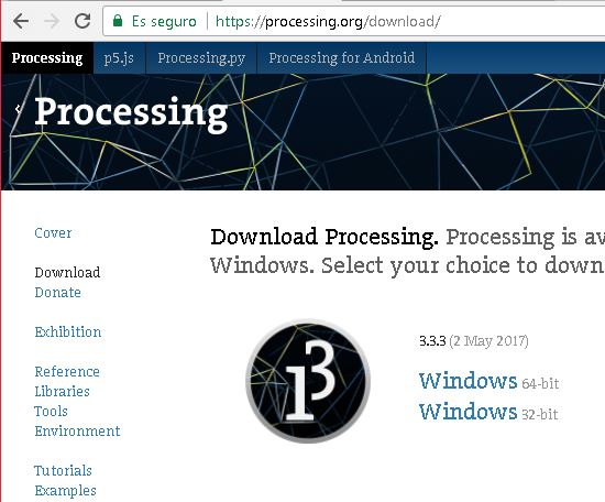
Processing is an open source computer programming language (simple) with and integrated environment
which mixes electronics and programming with visual arts.
Therefore, I went to www.processing.org and downloaded the version 3.3.3, released the May 2nd 2017.
Taking a deeper look on their website, as in arduino, there are several tutorials and definition
of each command used in the code. Nice and easy.
4. Communicating From The Computer To The Board
As done before when checking if the led worked, I went on the internet and read a tutorial to
communicate from the computer to the board. I found one very interesting: Controlling an RGB
Led With Arduino and Processing (http://www.instructables.com/id/Controlling-an-RGB-Led-with-
Arduino-and-Processing/).
The idea is, when the program is loaded into the board and processing has started, an image
like this appears on the screen
Then, with your mouse, by selecting one colour, it is transferred to the board and the RGB led shows the same colour.
Explaining theCode Processing
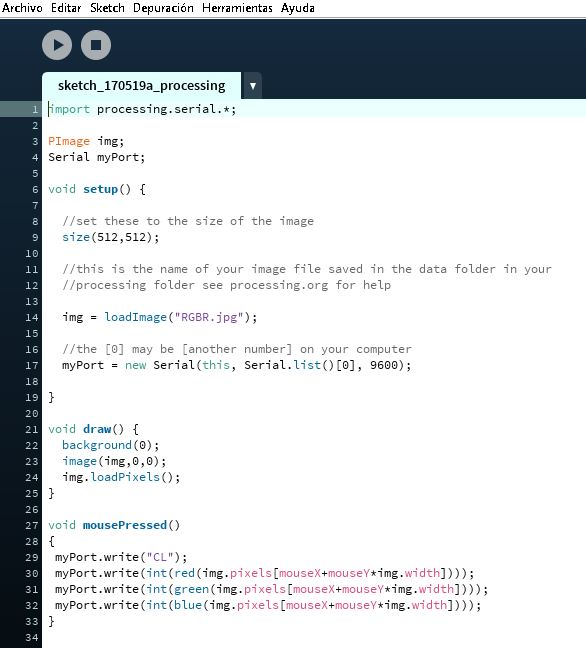
First, I import the processing.serial library to communicate with the board. Then I create a variable called
'PImage' and name it 'img and the serial variable and name it 'myPort'.
Secondly, with the set up, I define the display window with 512 pixels x 512 pixels, and loading RGBR.jpg image to the variable created before 'img'.
Thirdly, I draw on the display window described in setup, a background colour of black, being at the 0,0
(origin - remember the origin is at the top left of the display window) and creating a matrix of pixels
to identify each pixel to a position when the mouse is pressed.
Finally, I create the event 'mousePressed' so when the button mouse is pressed on top of one of the pixels
loaded on the matrix before, the program takes the information related to the colour of the pixels from
that position and transfers it to my port and into the board.
			import processing.serial.*;

PImage img;
Serial myPort;

void setup() {

  //set these to the size of the image
  size(512,512);

  //this is the name of your image file saved in the data folder in your
  //processing folder see processing.org for help

  img = loadImage("RGBR.jpg");

  //the [0] may be [another number] on your computer
  myPort = new Serial(this, Serial.list()[0], 9600);

}

void draw() {
  background(0);
  image(img,0,0);
  img.loadPixels();
}

void mousePressed()
{
 myPort.write("CL");
 myPort.write(int(red(img.pixels[mouseX+mouseY*img.width])));
 myPort.write(int(green(img.pixels[mouseX+mouseY*img.width])));
 myPort.write(int(blue(img.pixels[mouseX+mouseY*img.width])));
}
Arduino
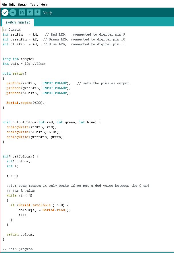
First, I start declaring variables for red, green and blue led to A4, A2 and A3 pin respectively.
Then I create a 32-bit variable named inByte, for reading the information coming through the port.
And finally a variable int for a 10 millisecond timing in ms.
In setup, I initialize the pin modes as outputs, and the baud rate of the serial communication to 9600.
Commands used:
-import: it is used to load a library into a processing sketch.
-PImage: creating variable to load and stores the selected image. Processing can upload .gif, .jpg, .png. This variable is directly related to 'loadImage'. Here we can name our variable 'img'.
-loadImage. loading image followed by its location.
-void setup(): initialization to define the environment properties such us screen size, loading the needed media; it is only ran once.
-size(x,y): defines the dimensions of the display window, corresponding x to the width units in pixels, and y to the height units in pixels.
-void draw(): the draw function continuously executes the lines of codes written inside it until the program is stopped or noLoop() is called.
-background(0): sets the background colour of the processing window.
-image(img,x,y): this function draws an image to the display windows. The image must have been loaded correctly to the sketch previously.
-loadPixels(): This function loads a snapshot of pixels on the current display window. This function must be called before reading or writing to 'pixels()'.
-void mousePressed(): This function is called when the mouse button is pressed.
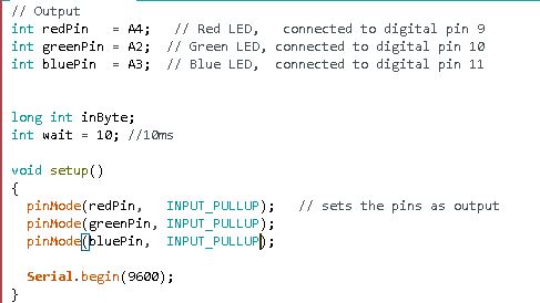
Problems
The code is done for a RGB led with a common cathode. Without noticing that at the beginning, the RGB values
were inverted and when selecting one colour, it came out another one. To correct this what I did was to change
the output to an Input_Pullup. But it did not work.
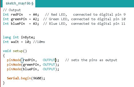
// Output
int redPin = A4; // Red LED, connected to digital pin 9
int greenPin = A2; // Green LED, connected to digital pin 10
int bluePin = A3; // Blue LED, connected to digital pin 11
long int inByte;
int wait = 10; //10ms
void setup()
{
pinMode(redPin, INPUT_PULLUP); // sets the pins as output
pinMode(greenPin, INPUT_PULLUP);
pinMode(bluePin, INPUT_PULLUP);
Serial.begin(9600);
}
void outputColour(int red, int green, int blue) {
analogWrite(redPin, red);
analogWrite(bluePin, blue);
analogWrite(greenPin, green);
}
int* getColour() {
int* colour;
int i;
i = 0;
//for some reason it only works if we put a dud value between the C and
// the R value
while (i < 4)
{
if (Serial.available() > 0) {
colour[i] = Serial.read();
i++;
}
}
return colour;
}
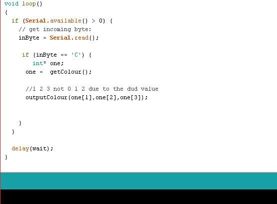
// Main program
void loop()
{
if (Serial.available() > 0) {
// get incoming byte:
inByte = Serial.read();
if (inByte == 'C') {
int* one;
one = getColour();
//1 2 3 not 0 1 2 due to the dud value
outputColour(one[1],one[2],one[3]);
}
}
delay(wait);
}
5. Communicating From The Board To The Computer
For this program, I went to https://processing.org/tutorials/electronics/ and starting reading what it can be
done with the switch I have on my board. I arrived to an example program that consists of creating
a black rectangle on the display window. When you press the button on the board, the rectangle becomes
light gray. Once you stop pressing the button, it becomes black again.
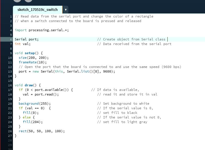
Explaining the Code Processing
First, I import the library processing.serial.* as done on the previous example to communicate through
the port. Then I create the variables Serial named as port, and an int variable for the value.
Then, in setup, I determine the size of the display window (200 pixels by 200 pixels) and have a
frameRate of 10 times per second. After that, defining where to find my port at a baud rate of 9600.
For the loop ('void draw'), if there is a value available on the port, it reads it and stores it on the int named 'val'.
At the end, having a 255 value for the background, if the value received is equal to 0, the fill inside
the rectangle must be 0 (black). If it isn't, then it must fill the rectangle with a 204 colour (light
grey). Then, the rectangle dimensions are determined ( position x: 50, position y: 50, 100 pixels
for width, 100 pixels for height).
Commands used (without repeating previous ones explained before):
-'frameRate(x)': this function specifies the number of frames (x) displayed each second. In this case, it redraws the rectangle 10 times per second.
-'fill(x)': sets the colour used to fill the shape.
-rect (x,y, width, height): draws a rectangle on the display window.
// Read data from the serial port and change the color of a rectangle
// when a switch connected to the board is pressed and released

import processing.serial.*;

Serial port;                             // Create object from Serial class
int val;                                 // Data received from the serial port

void setup() {
  size(200, 200);
  frameRate(10);
  // Open the port that the board is connected to and use the same speed (9600 bps)
  port = new Serial(this, Serial.list()[0], 9600);
}

void draw() {
  if (0 < port.available()) {         // If data is available,
    val = port.read();                   // read it and store it in val
  }
  background(255);                       // Set background to white
  if (val == 0)  {                       // If the serial value is 0,
    fill(0);                             // set fill to black
  } else {                               // If the serial value is not 0,
    fill(204);                           // set fill to light gray
  }
  rect(50, 50, 100, 100);
}
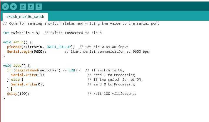
Arduino
First, I declare variable for pin 3 (where my button is connected to). The running the setup,
I activate the mode to Input_pullup with a Serial connection at a 9600 baud rate.
For the loop, if the pin reads LOW, it means the my button is ON as it is configured as an
INPUT_PULLUP. Then number 1 is sent to the computer via serial communication. If the pin is
HIGH, then send 0 to the computer and delay 100 milliseconds.
			// Code for sensing a switch status and writing the value to the serial port

int switchPin = 3;  // Switch connected to pin 3

void setup() {
  pinMode(switchPin, INPUT_PULLUP);  // Set pin 0 as an input
  Serial.begin(9600);         // Start serial communication at 9600 bps
}

void loop() {
  if (digitalRead(switchPin) == LOW) {  // If switch is ON,
    Serial.write(1);                     // send 1 to Processing
  } else {                               // If the switch is not ON,
    Serial.write(0);                     // send 0 to Processing
  }
  delay(100);                            // Wait 100 milliseconds
}
6. My Program -
As now I have understood how the board and the computer talk to each other, I want to go further on experimenting a little bit more with processing with colour and shapes.
I went again to
and continued reading on how to create different shapes.
On the other hand, for the colour of my shape, I only have used the fill (205) and the fill (255), corresponding to monochromatic colours. I wanted to add a little more colour to my program.
New commands used:
TRIANGLES
It is plane created by connecting three points. The three points are specified by pairs, having six numbers (three pairs), to define the position of each point:
'triangle ( x1, y1, x2, y2, x3, y3);'
-x1 and y1: x and y coordinate of the first point.
-x2 and y2: x and y coordinate of the second point.
-x3 and y3: x and y coordinate of the third point.
-The one I have used:
'triangle (288, 18, 451, 460, 488, 460);'
'triangle ( 150, 150, 451, 460, 488, 460);
ARCS
Draws an arc on the screen. The arc is drawn along the outer edge of an ellipse defined by a, b, c and d. Using the start and stop parameters to specify the angles at which to draw the arc.:
'arc( a, b, c, d, start, stop);'
-a: x coordinate of the arc's ellipse
-b: y coordinate of the arc's ellipse
-c: width of the arc's ellipse
-d: height of the arc's ellipse
-start: angle to start the arc, in radians
-stop: angle to stop the arc, in radians.
-The one I have used:
'arc(479, 300, 280, 280, PI, TWO_PI);
QUADRILATERALS
The first pair of parameters set the position of the first vertex, and the next pairs the next vertex and so on. The command:
-
-x1 and y1: x and y coordinate of the first corner.
-x2 and y2: x and y coordinate of the second corner.
-x3 and y3: x and y coordinate of the third corner.
-x4 and y4: x and y coordinate of the fourth corner.
-The one I have used:
'quad (189, 18, 216, 19, 216, 360, 144, 360);'
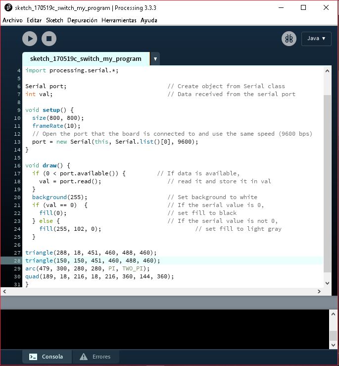
Processing
The modifications I have done is:
-having a bigger screen: 800x800px
-having different shapes
-including colours
-using new commands
Arduino
The board's code is the same as the second test I have done, connecting the board to the computer. When the button is pressed, it changes on the screen.
Processing: Code
import processing.serial.*;

Serial port;                             // Create object from Serial class
int val;                                 // Data received from the serial port

void setup() {
  size(800, 800);
  frameRate(10);
  // Open the port that the board is connected to and use the same speed (9600 bps)
  port = new Serial(this, Serial.list()[0], 9600);
}

void draw() {
  if (0 < port.available()) {         // If data is available,
    val = port.read();                   // read it and store it in val
  }
  background(255);                       // Set background to white
  if (val == 0)  {                       // If the serial value is 0,
    fill(0);                             // set fill to black
  } else {                               // If the serial value is not 0,
    fill(204);                           // set fill to light gray
  }
  triangle(288, 18, 451, 460, 488, 460);  //triangle formation
  triangle (150, 150, 451, 460, 488, 460); //triangle formation
  arc(479, 300, 280, 280, PI, TWO_PI); //arc formation
  quad(189, 18, 216, 18, 216, 360, 144, 360);  //quadrilateral formation

}
Arduino: Code
int switchPin = 3;  // Switch connected to pin 3

void setup() {
  pinMode(switchPin, INPUT_PULLUP);  // Set pin 0 as an input
  Serial.begin(9600);         // Start serial communication at 9600 bps
}

void loop() {
  if (digitalRead(switchPin) == LOW) {  // If switch is ON,
    Serial.write(1);                     // send 1 to Processing
  } else {                               // If the switch is not ON,
    Serial.write(0);                     // send 0 to Processing
  }
  delay(100);                            // Wait 100 milliseconds
}