Fabacademy 2017
Final Project Process
Index
1.Project management
Fab Window
Most of the digital fabrication building methods for architecture that I'm aware of are focused on complete systems rather than using a "building block" approach so I'm interested in exploring this route for my final project.
Windows are quite fascinating building elements for many reasons:
- They are as old as Architecture itself.
- They are not static.
- They have been the first ones incorporating the latest technologies in each period (glass panes, metal frames, domotics, etc…).
- They are ubiquitous and banal.
So the starting idea is to develop a window design which will have to meet the following main goals:
- Timber structure.
- Fabricating as many elements using fab lab technologies.
- Design should be up to current Eurocode standards on thermal insulation, waterproofing, structural integrity, fire resistance and safety.
- Design should include some input output devices such us temperature, air quality and light sensors, mechanical actuators, motorized solar control and so on.
2.Design tools
Timber Window manufacturing
Most of the digital fabrication building methods for architecture that I'm aware of are focused on complete systems rather than using a "building block" approach so I'm interested in exploring this route for my final project.
The starting idea is to develop a window design which will have to meet the following main goals:
- Timber structure.
- Fabricating as many elements using fab lab technologies.
- Design should be up to current Eurocode standards on thermal insulation, waterproofing, structural integrity, fire resistance and safety.
- Design should include some input output devices such us temperature, air quality and light sensors, mechanical actuators, motorized solar control and so on.
Router and power tool manufacturer Trend-uk.com shows the process of building a timber window.
Despite a window can appear at first as a simple building component, they are generally quite sophisticated engineering and design elements which requires a substantial number of tools and multiple fabrication steps. So in order to make sure that the design would have a high performance I started analysing their shapes at a 1:1 scale.
I used swiss and german construction manuals a my primary reference material, specifically Constructing Architecture by Andrea Deplazes and Building Openings Construction Manual by Jan Cremers. Both countries have extremely high standards for timber window construction so it would be a great starting point for the project.
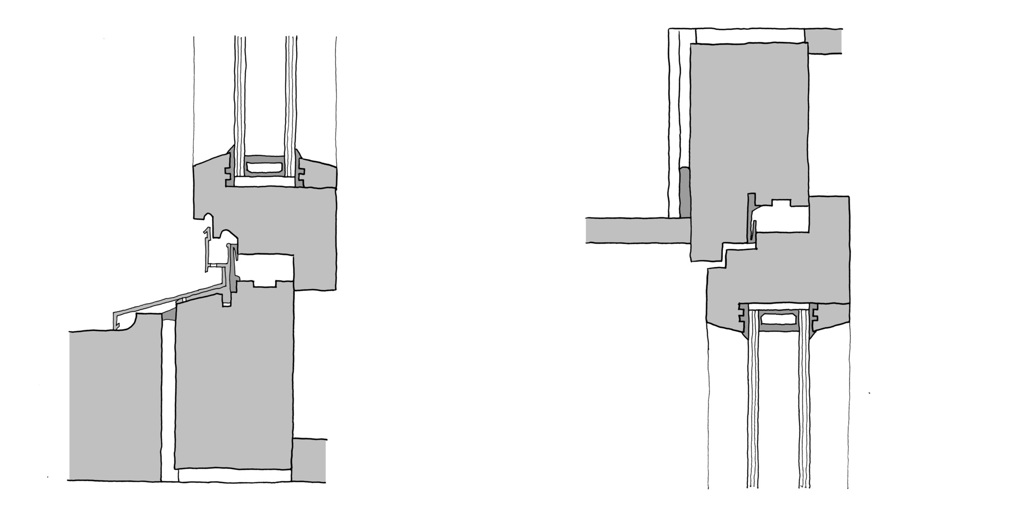
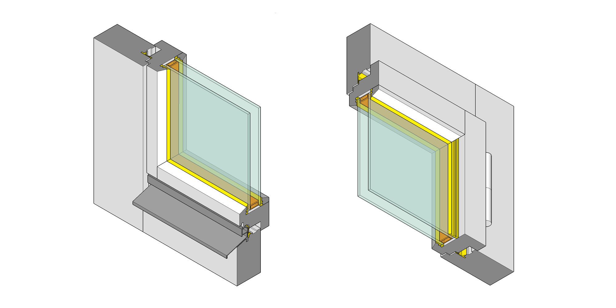
I sketched timber windows details both horizontal and vertical sections, making sure that all the different design features were properly identified. It has been a quite fascinating process to understand the reasoning behind these profiles.
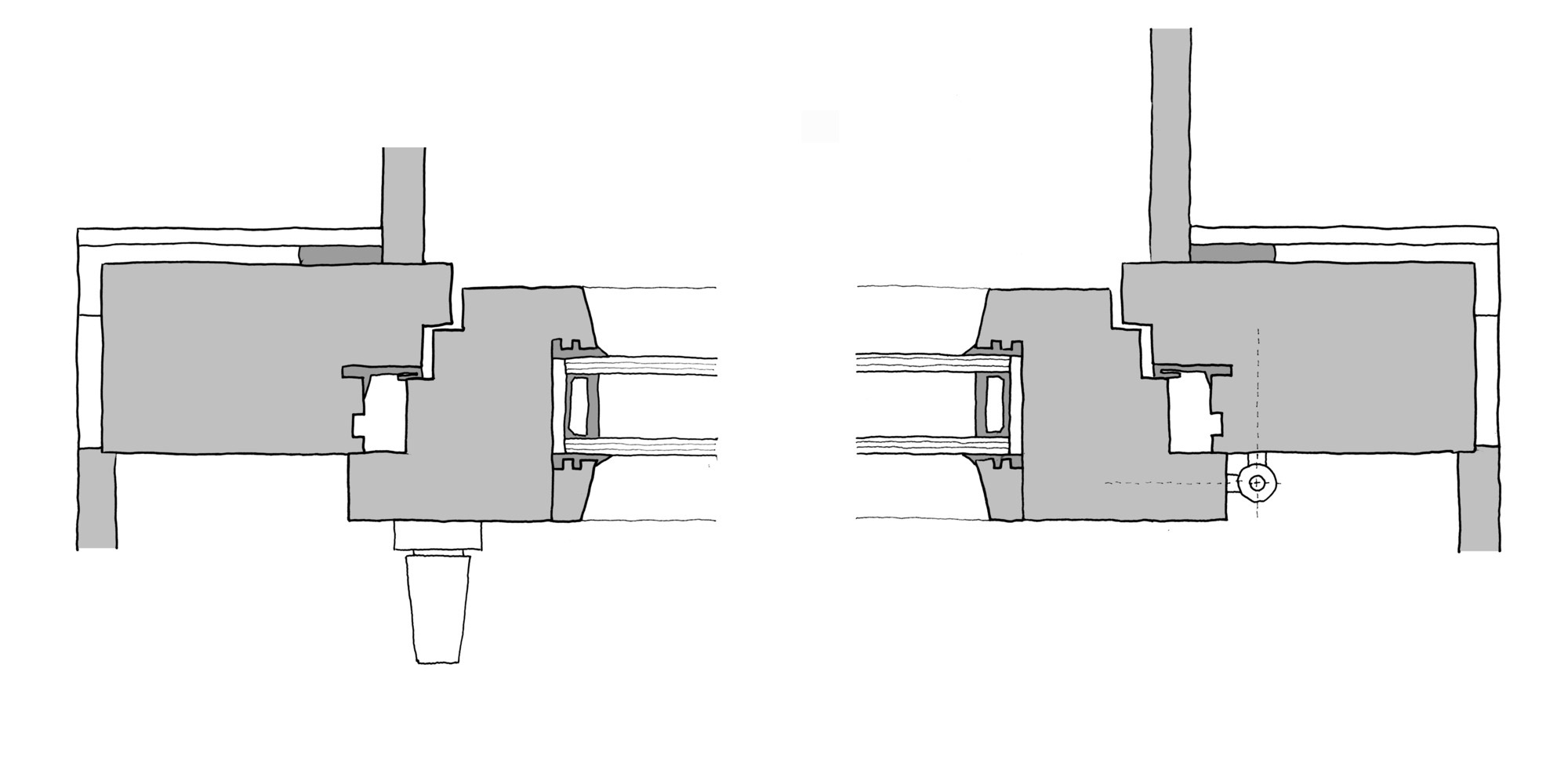
Identified window elements:
- Outer frame. The outer frame is part of the window; it is fixed to the opening rebate in the reveal.
- Sash frame. The sash frame is rebated and carries the glazing. Various styles of opening are possible.
- Reveal. The reveal is the vertical side of the structural opening to which the jamb of the outer frame is fixed; its depth is equal to the thickness of the wall.
- Weatherstripping in frame rebate.Fitted to all sides of the window, the weatherstripping ensures a windproof fit preventing ingress of noise.
- Erection tape. A compressible sealing strip seals the jamb against the outer part of the reveal.
- Setting block. Setting blocks help to align the glazing temporarily before it is fixed in position.
- Glazing bead,The glazing bead is part of the sash frame and fixes the glazing in position. It is removable.
- Rubber gasket.The gasket creates a windproof seal and fixes the glazing in the frame
- Insulating glazing. two panes of glass bonded together on all sides via a spacer hermetic edge seal
- Hardware.Hardware is the overall term for the components required to assemble operate or secure the window
- Lintel a loadbearing component, is the horizontal termination of the structural opening.
- Rebates. Stepped interface between outer frame and sash frames, with peripheral weatherstripping.
- Rainwater drainage channel This channel is included to collect any water in the outer rebates of the window frame and drain it to the outside.
- Weatherstripping in frame rebate Fitted to all sides of the window, the weatherstripping ensures a windproof fit preventing ingress of noise.
- Weather bar The weather bar is required only along the bottom edge of the window; it drains the driving rain from the front of the window and from the frame rebates at the sides. It must be sealed against the sill member and the reveals (compound or gasket).
- Window sill The window sill forms the horizontal termination at the bottom of the opening. It is given a gentle fall so that water can drain to the outside. Special care is needed at the ends of the window sill. It must be ensured that water on the window sill cannot seep sideways into the reveals.
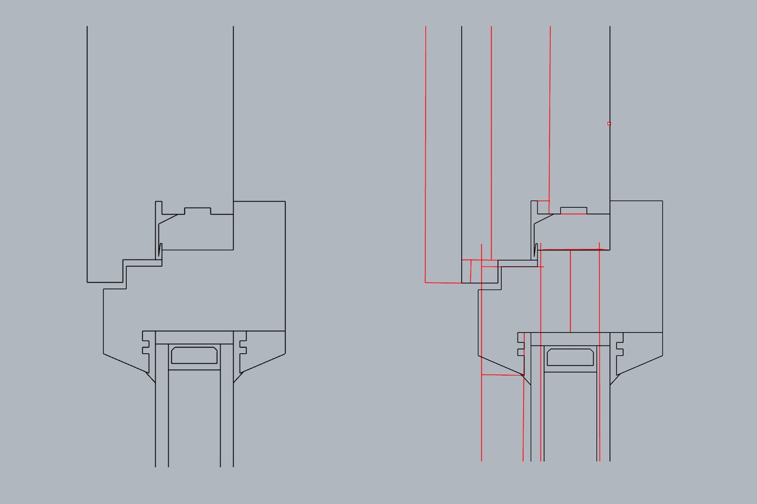
Rhinoceros
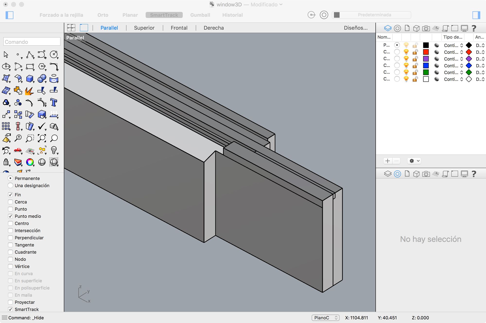
From this 1:1 (real scale) sketch models, I started to measure and draw them into horizontal and vertical vector views which would be used to build the 3D geometry. Rhinoceros is excellent for drawing fast and precise as it uses nurbs (non-uniform rational B-spline) in its geometry engine.
SketchUp
While I was modeling in Rhino, I realize that the finger joints were much more sophisticated than I first assumed and while Rhino is great for precision, Sketchup is really fast and interactive for pushing and pulling the geometry so I drew it in SketchUp to figure out the specific finger joint pattern. At this point I started to think on the final project fabrication process too.
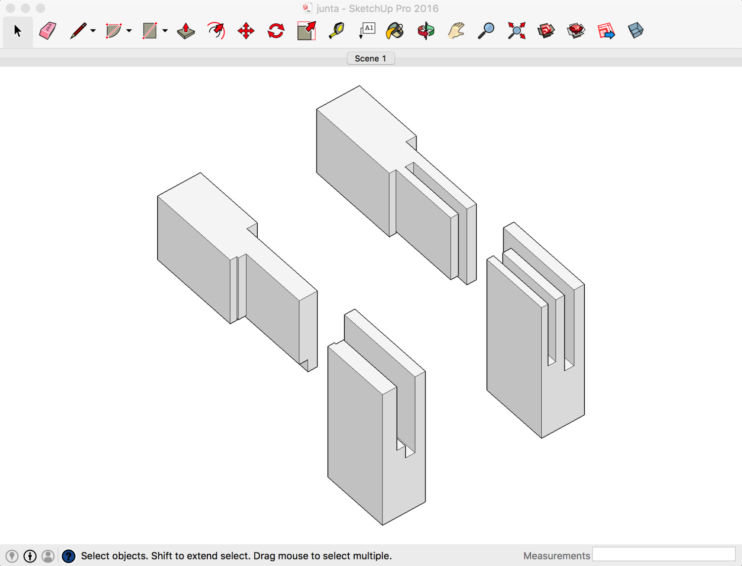
I tested three and one finger joints and based on the thickness of the frame a single finger joint seems much more adequate, I will need to test this joint on a physical prototype before validate it completely.
Complete Model
Went back to Rhino and "carved" the joints using bolean operations. I wasnt entirely happy with the way Rhino represents polysurface objects and I couldn't find a simple way to display coplanar surfaces as a single surface. Back again to SketchUp! SketchUp display settings are quite flexible so it is super fast to represent the geometry using isometric projection and setting different thicknesses for the outlines and edge lines.
I drew all the different elements and grouped them coherently using the Outliner panel, set up a couple of isometric views and exported as a raster png. Finger joints are much more complicated that I anticipated it is going to be a an interesting challenge to make a design that performs well and it is simple to fabricate and assembly.
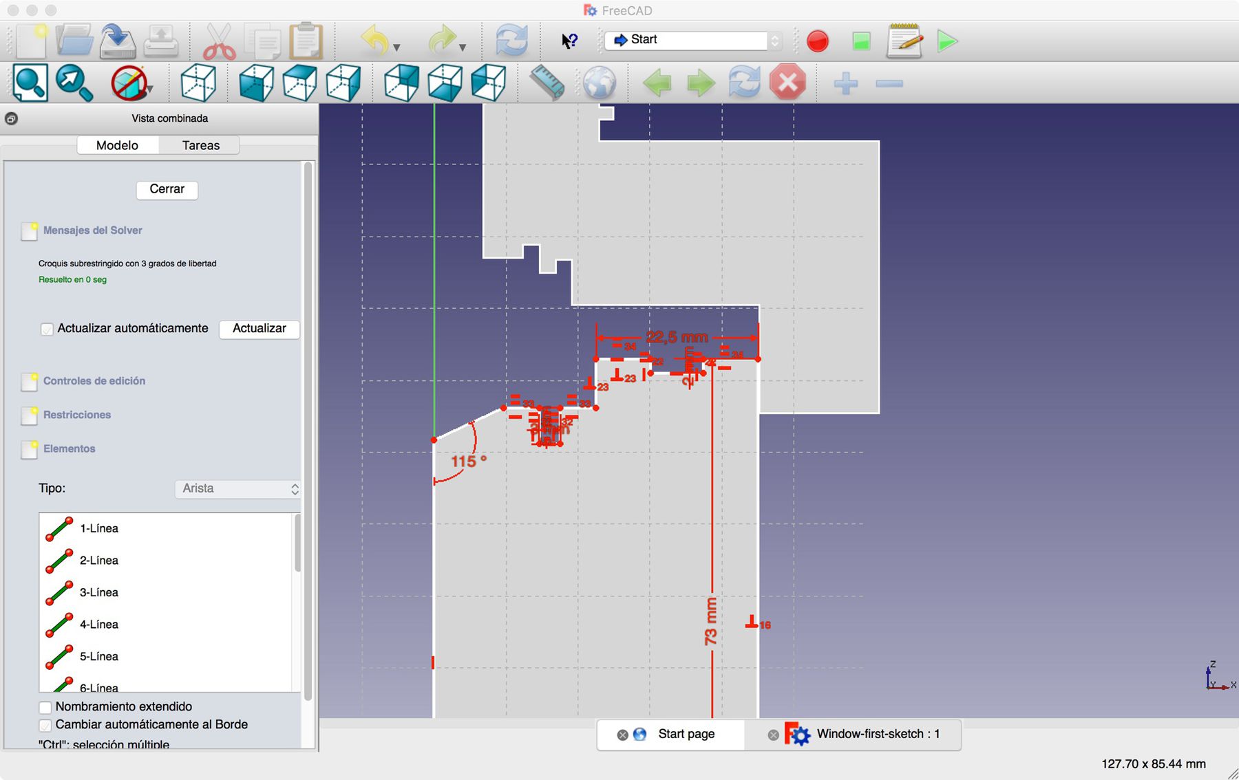
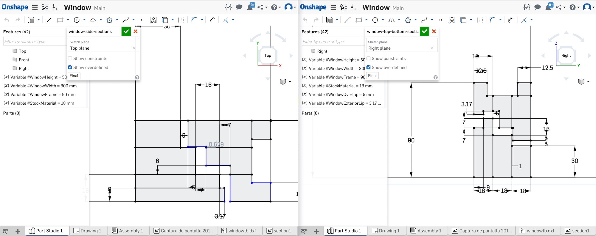
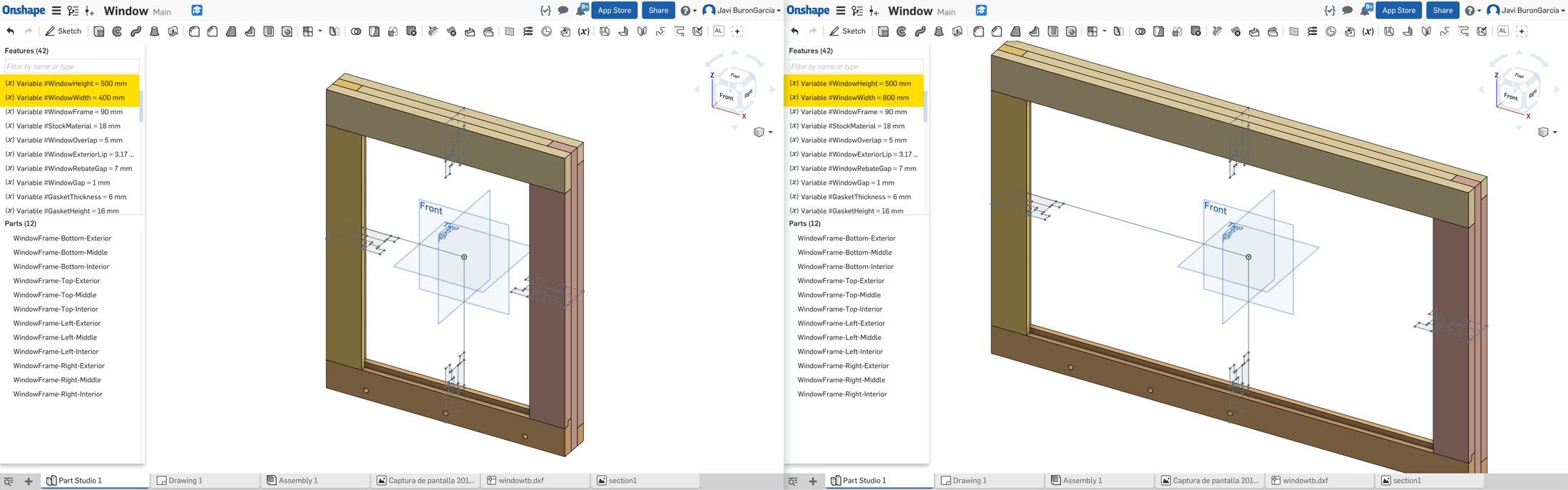
Parametric modelling
Finally, once I had a much clearer understanding of the dimensions, relationships and tridimensional shapes, I started building a parametric model in Freecad that will allow me to iterate the design faster once I start prototyping. Never used Freecad before, it feels powerful but the modelling process seems to be very structured so I think it has been useful to model and analyze things first with SketchUp and Rhino.
3.3D scanning and printing
Latch and handle
This week's task was to start 3D printing and scanning and by doing so develop designs that take advantage of the unique characteristics of additive manufacturing. In additive manufactured objects, designers have great control on not only the boundary of the object but the structure of the 3D printed object itself. This opens up an unprecedented flexibility to transform the object’s strength-to-weight ratio or the position of the object’s center of mass for example.
I would like to explore the possibilities of additive manufacturing for certain components of my window project.
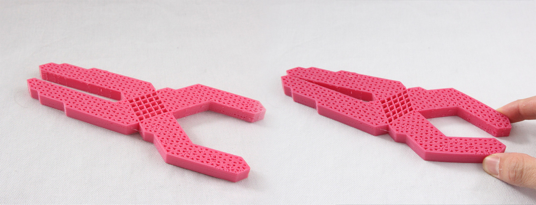
Metamaterials mechanisms
On my research on functional additive manufacturing mechanism I found This paper by a group of researchers –Alexandra Ion, Johannes Frohnhofen, Ludwig Wall, Robert Kovacs, Mirela Alistar, Jack Lindsay, Pedro Lopes, Hsiang-Ting Chen, and Patrick Baudisch– of the Hasso Plattner Institute in Germany about Metamaterials mechanisms.
Metamarials are artificial structures with mechanical properties that are defined by their usually repetitive cell patterns, rather than the material they are made of.
As the authors explain in the paper, the research explores the idea of considering metamaterials as machines rather than just materials by creating objects that allow for controlled directional movement. This allows users to create objects that perform mechanical functions.
7.Computer-Controlled Machining
First full size mockups
The main objective of this project is to create a design and manufacturing process for a high performance window that can be replicated in any fab lab with the standard Fab Lab equipment and accessible materials. Plywood is an interesting choice as it provides a good weight to strength ratio, decent durability and a broad range of qualities and prices.
A 8x4 flat CNC milling machine would be the preferred tool as well. In order to make the design accessible to entry users with limited skills, I will try to simplify the milling process as much as possible, avoiding complicated jigs and registration processes.
Woodworking Tips - FELDER window set IV 78 Part 1 - Felder Group
How to fabricate a complicated timber profile which is normally made in multiple routing steps using dedicated (and expensive) router bits? The first decision would be to achieve these profiles by dividing them in simpler sections –using simple pocketing and profiling operations– and assembling them later.
There are certain shapes that will be much harder to replicate using this process by in exchange manufacturing and assembly process should be greatly simplified making the fabrication of a window a process that most people could undertake as a weekend project. I would like to experiment with using certain specialized bits to enhance or improve the design something like a "basic" and a "pro" version of the design.
For this first prototype I worked on the outer frame and left the sash frame for the next iteration. A 54mm (18mmx3) depth frame seemed adequate as it can fit a double glass comfortably without adding too much weight.
I decided that the I/O element of the design –light sensors and a an automatically actuated window blind– would be clamped to the frame externally so wiring and electronics can be accessed without removing the window entirely.
For this prototype I used the same ply –medium grade ply– than the baby walker but I am thinking is trying furniture grade birch ply instead. Using ply instead of solid timber is going to represent significant savings in any case. Same compression bit was used too, for a 500mm by 400mm window the whole job took less than 8 minutes.
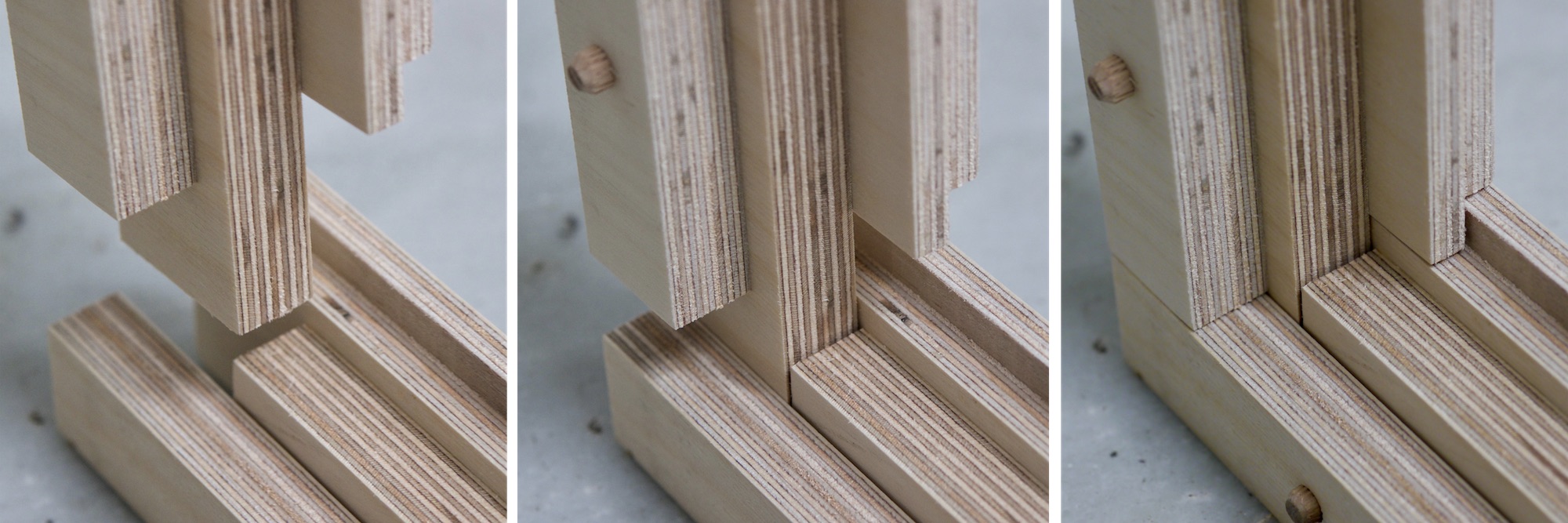
Made a significant mistake when processing the exported drawing from Onshape into V-carve Pro and 8mm hole for the dowels cut all the way through the exterior and interior faces, next iteration wont have those holes.
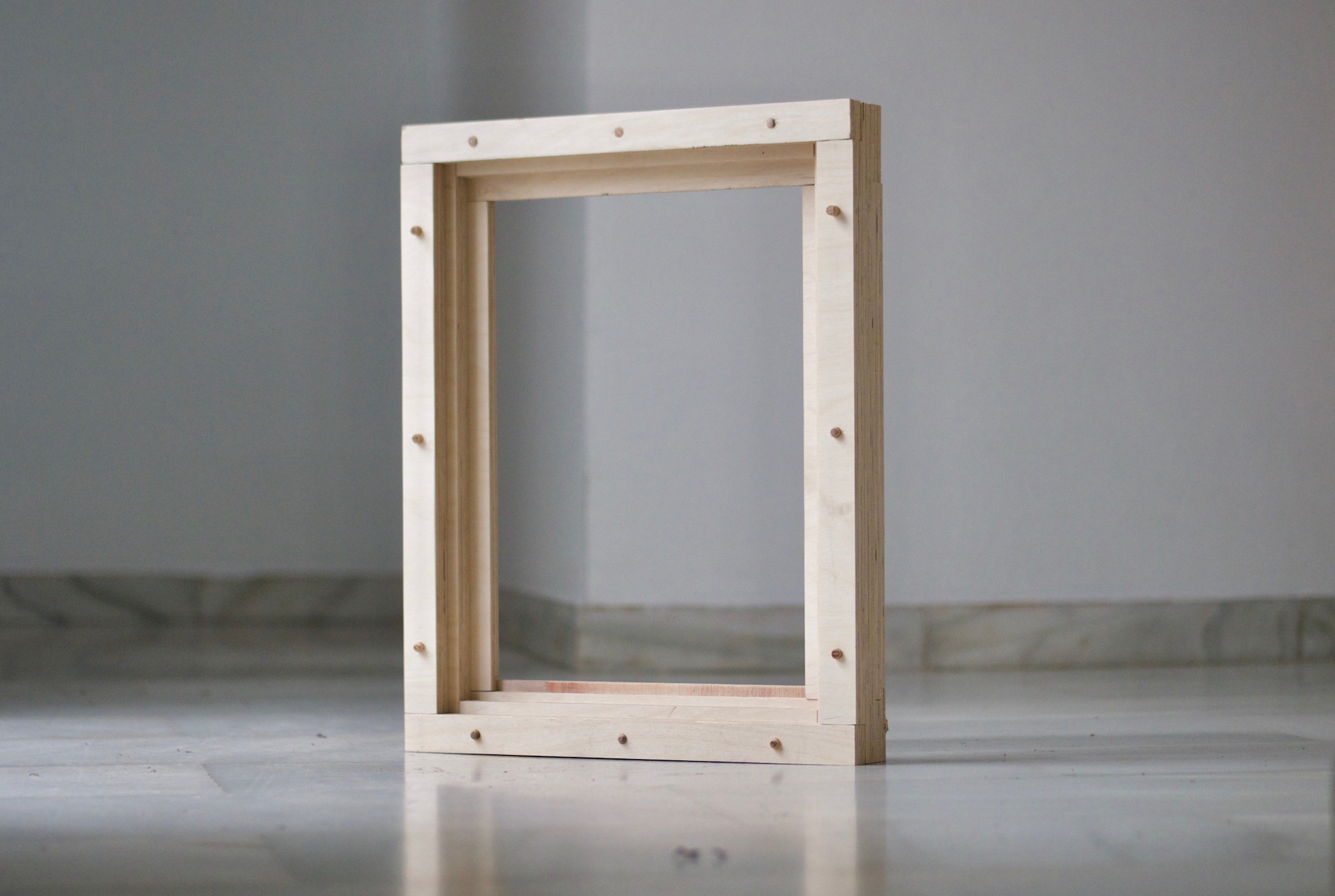
Pieces were quite promising in my opinion, they feel robust and sharp. All the parts fitted together precisely. I havent glued anything yet, will give it a go next weekend. I'm not entirely happy with the bottom element as I need to drain water to the outside, I will have a better understanding of how to solve this once I cut the sash frame.
Tenth task
Output devices
This week task is to design, make and programme a board controlling an output device. I will use this week task to work on my final project and control a DC motor for the roller blinds of the fab window.
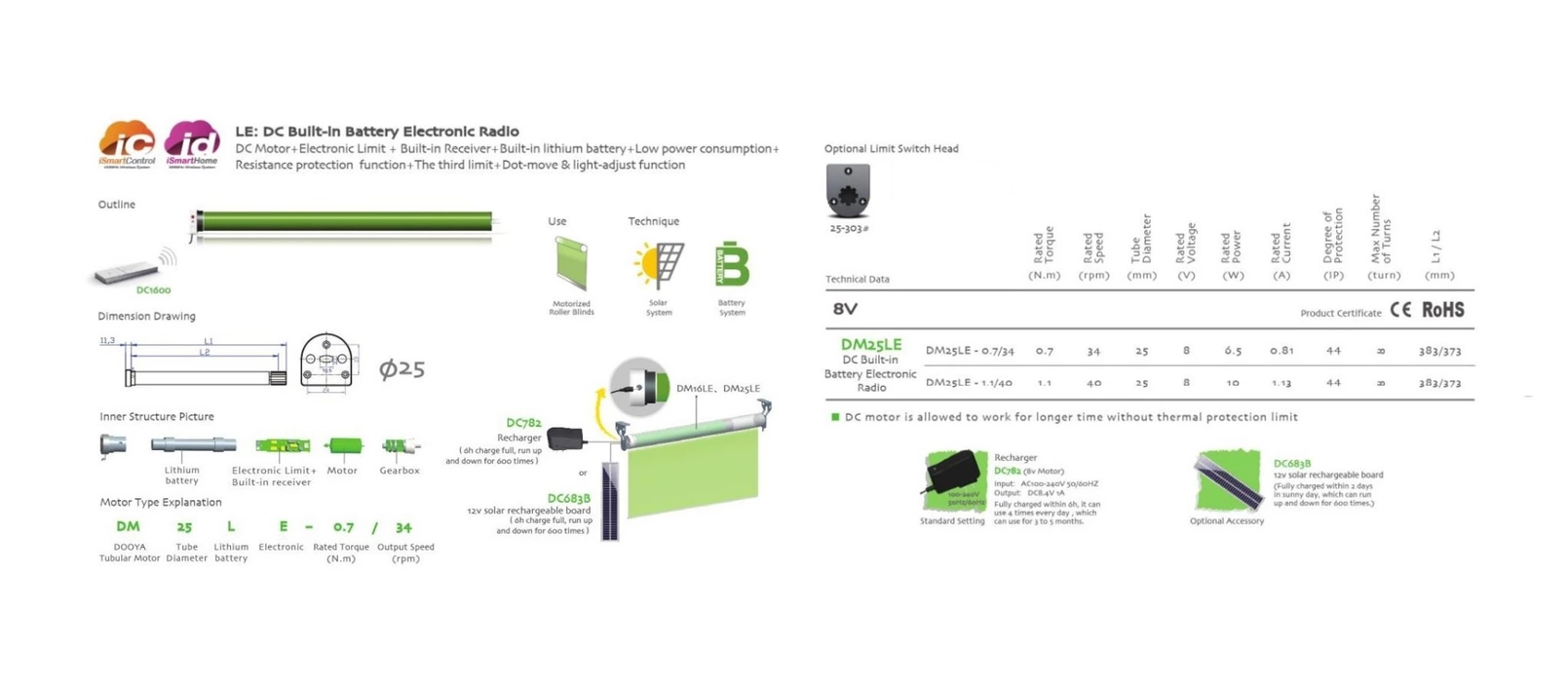
This is a good resource for calculating the neccesary torque of a roller blind DC motor. I am still not sure the final size of my window so I opted for a medium range torque of 1N.m. I also found a manufacturer which provides DC motor and the reduction gearbox in a handy format that can be installed inside the roller blind inner tube so it will keep things much tidier than installing the motor on one side.
This specific model also includes a battery which I will use to power the whole system. It brings its own controller circuit with a built in radio reciever which they will not be used, I will be using my own designed boards. It needs 8V and 0.81 Amps.
Designing the board
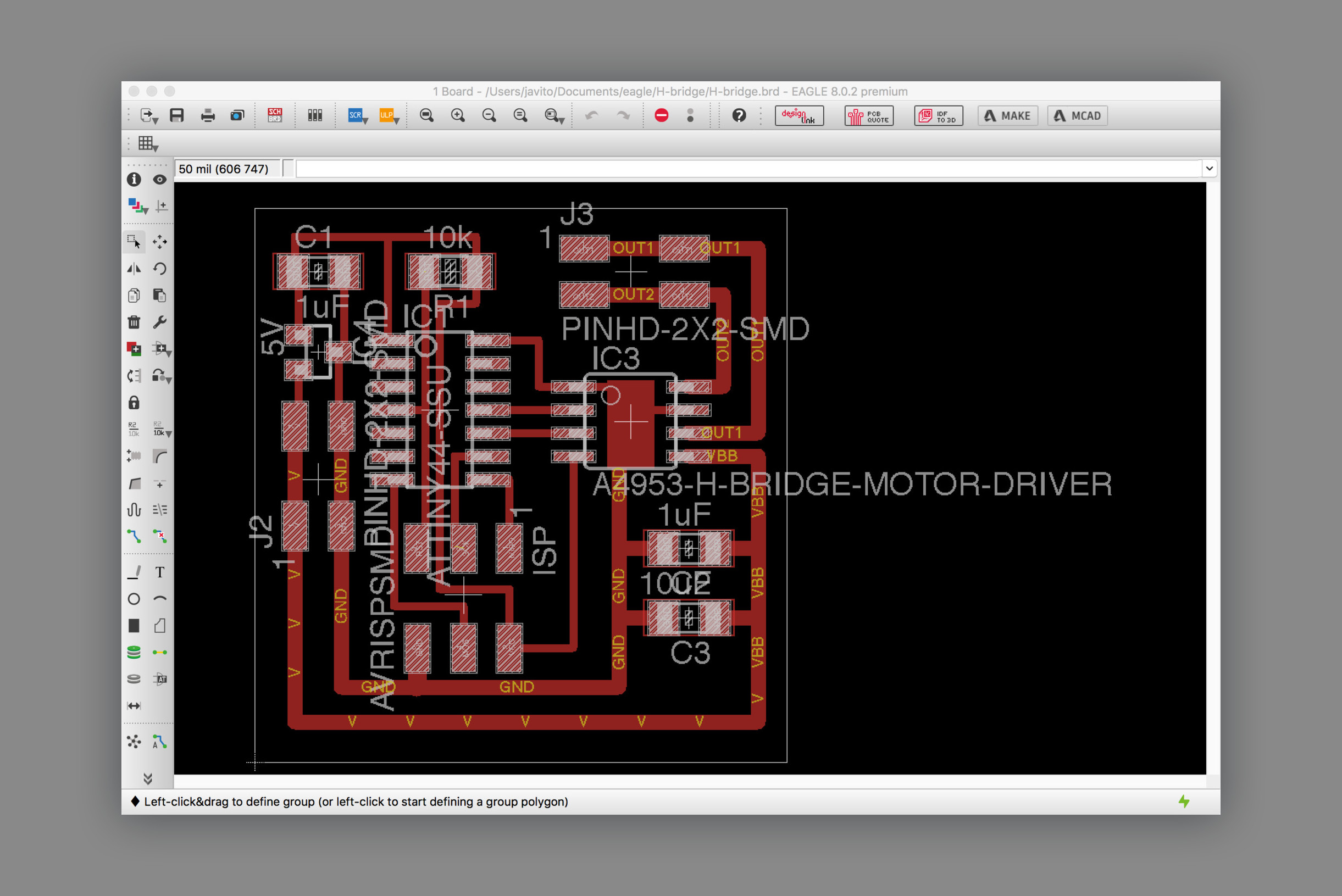
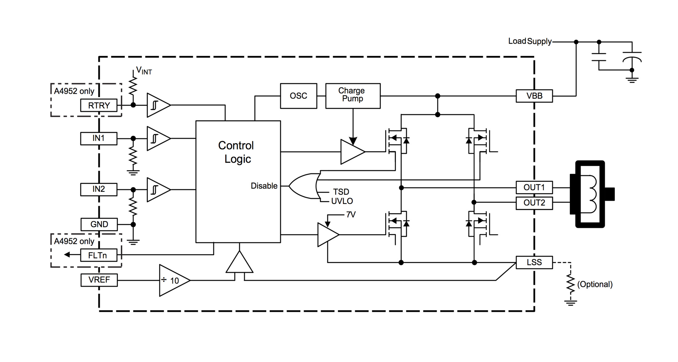
hello.H-bridge.44 board was used as a reference. It uses the A4953 Full-Bridge DMOS PWM Motor Driver which as its datasheet state "…is capable of peak output currents to ±2 A and operating voltages to 40 V". The chip has an exposed thermal pad for heat disipation.
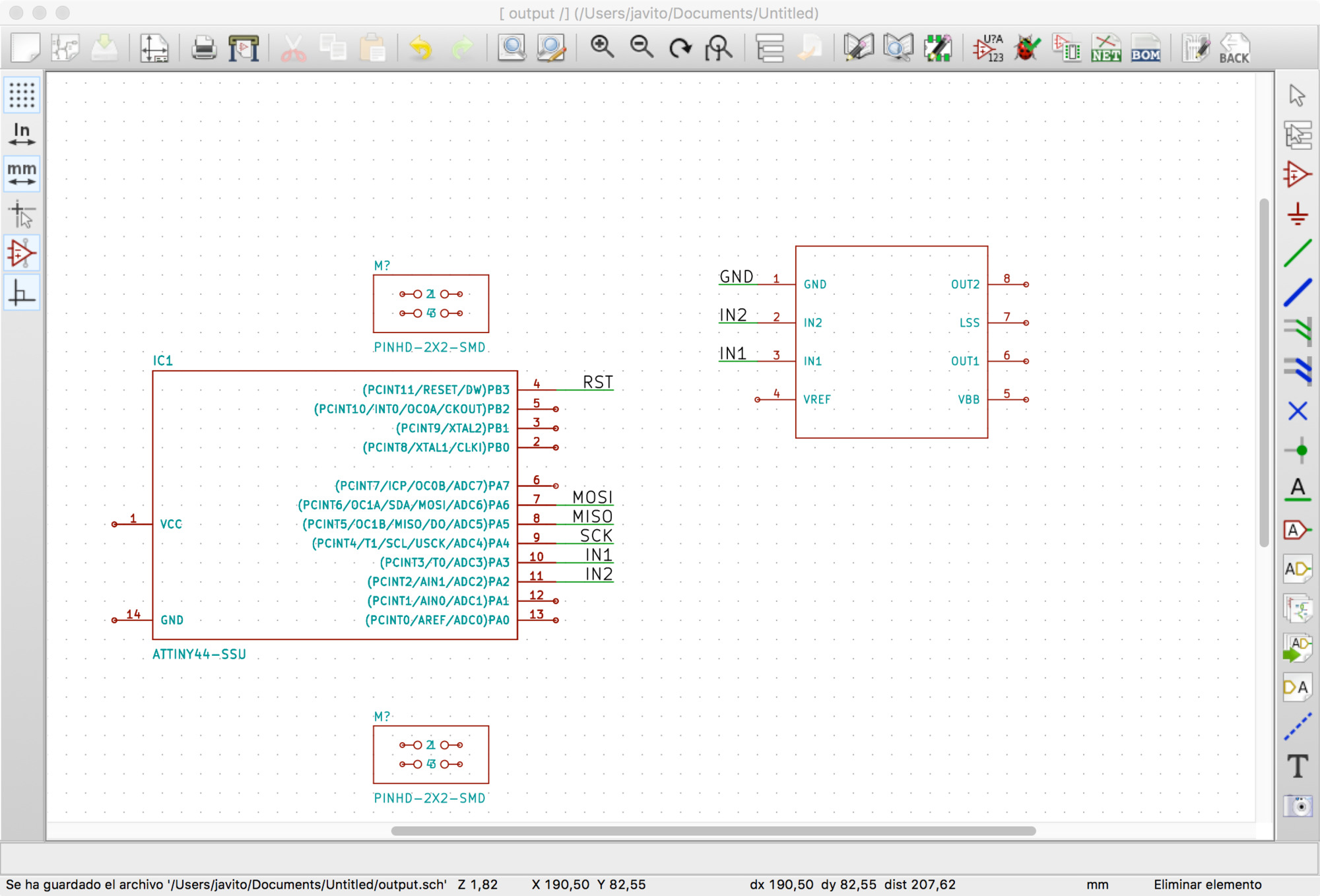
I decided to give a go to Kicad to have an Open Source alternative to Autodesk's Eagle. Interface was simple and felt more responsive than Eagle, I had huge problems with the libraries though which didnt feel as complete and sound as Eagle's ones. Had numerous issues when double checking the circuit and tried to customize the components myself but after a few hours of fiddling with them without much results I decided to go back to Eagle. Will try again at some point!
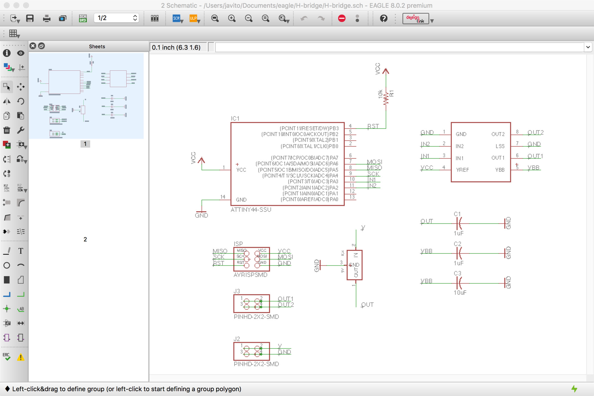
Back in Eagle, drawing the schematic was fast. I wonder if there is a grammar for electronic schematics as it is an abstract representation of a circuit, something must be in place to facilitate circuit reading. Anyway, the schematic completed in Eagle.
Placing the components and routing is always an interesting design challenge, with each new board the process fells more confortable and enjoyable. A couple of things to keep in mind for this board was to calculate the width for the motor supply routes and to draw a heat sink below the motor driver. For the first one, I used one of the many online calculators and entered the peak voltage and amps for my DC motor. It turned out that a 32mil width would be sufficient so I could keep the routes width multiple. I'm using 16mil for the small ones. For the second, I drawn a rectangle on top of the traces on layer 1, this caused some overlaping errors when checking the design rules which I simply approved manually.
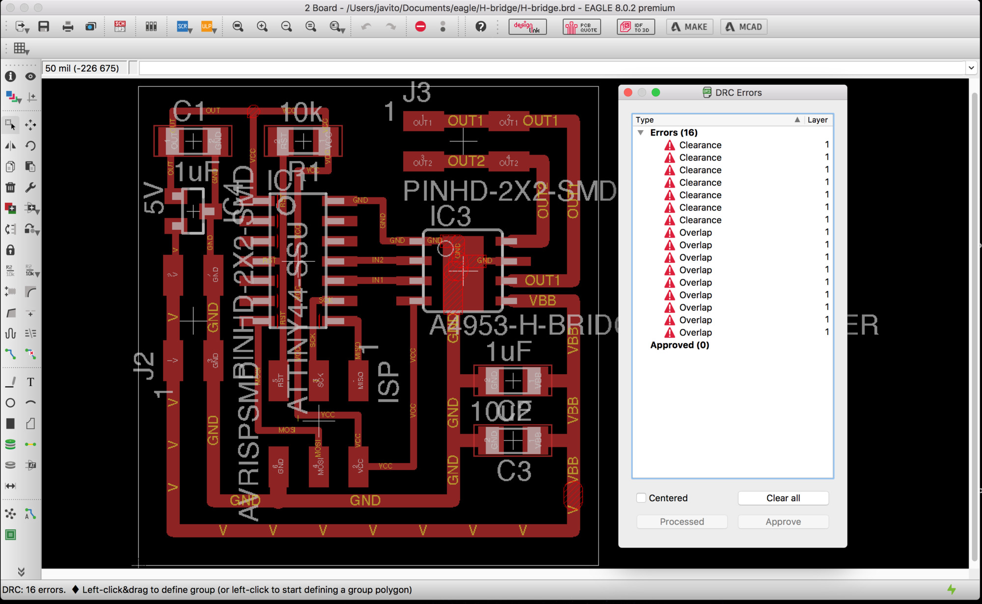
For the clearance error, I simply decrease the grid sbudivision to 5mil and placed the interior routes evenly. Below the final board design.
Fabricating the board
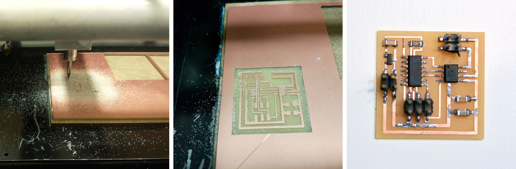
At this point, we are quite familiar with this process: Exporting png from Eagle –remember if you are using Mac with retina display you have to scale down the resulting image 50%–, using Mods to calculate the trace and cutting paths, milling the board and soldering the components. There were no remarkable issues.
Reusing roller blind DC motor
Once the part arrived I proceeded to its full disasembly. The process was more difficult than expected, no screws at the ends and all the internal elements were secured with two pins flushed with the tube. I cut a small groove at the center and used a flat screwdriver to remove them. The logic board had a clever design to attach it to the DC motor splitting the board into two perpendicular boards, slotting the main on into the other and securing it with solder.
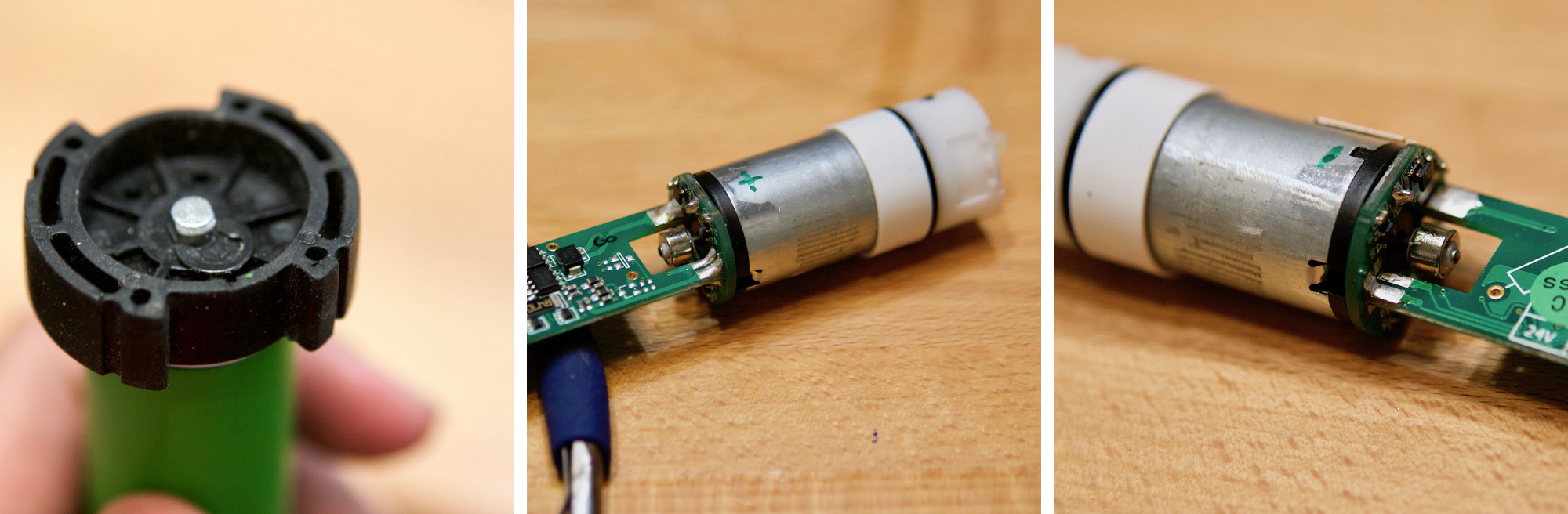
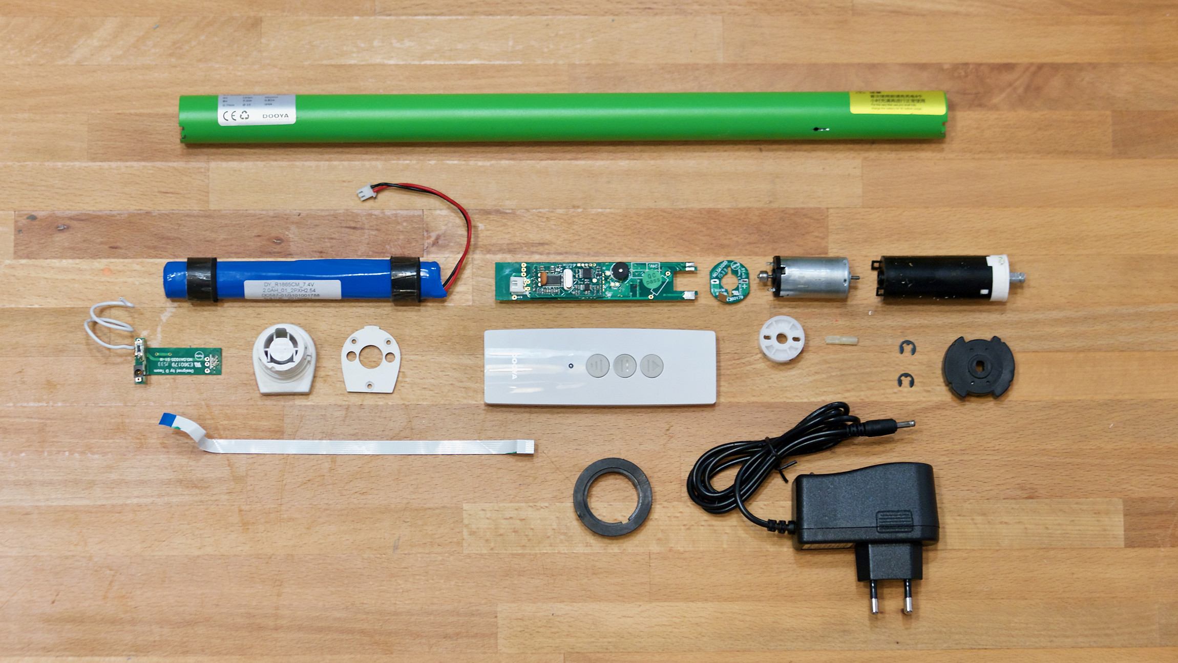
Below you can see all the different parts of this clever design. I will be reusing the metal tube and most of the mechanical parts, the DC motor, the reduction box and the battery pack –together with its small charging circuit–. I will making my own controlling board which will have the same form factor than the shipped one.
Programming and testing
FOr programming I used hello.H-bridge.44.DC.c as a reference but for the moment I wont use PWM to control the speed of the motor. I will just program the board to move the motor forward and reverse. There are a number of things to learn this week:
- In my Embedded programming assigment I wrote the register directly with the byte in binary, this week I would like to use bitwise operators instead as it is used on the example above. I found a good tutorial in tutsplus Bitwise operations tutorial
- The physics of a DC motors defines the way motor drivers work, I have to study A4953 DC Motros driver datasheet in detail.
- If you are driving inductive loads, whereas it is a brushed or brushless DC motor, stepper motor, solenoid or a relay, you must have experienced a little bit of a problem in the form of an unwanted current flowing in the unwanted direction. This page explains Slow, mixed and fast decay modes in detail.
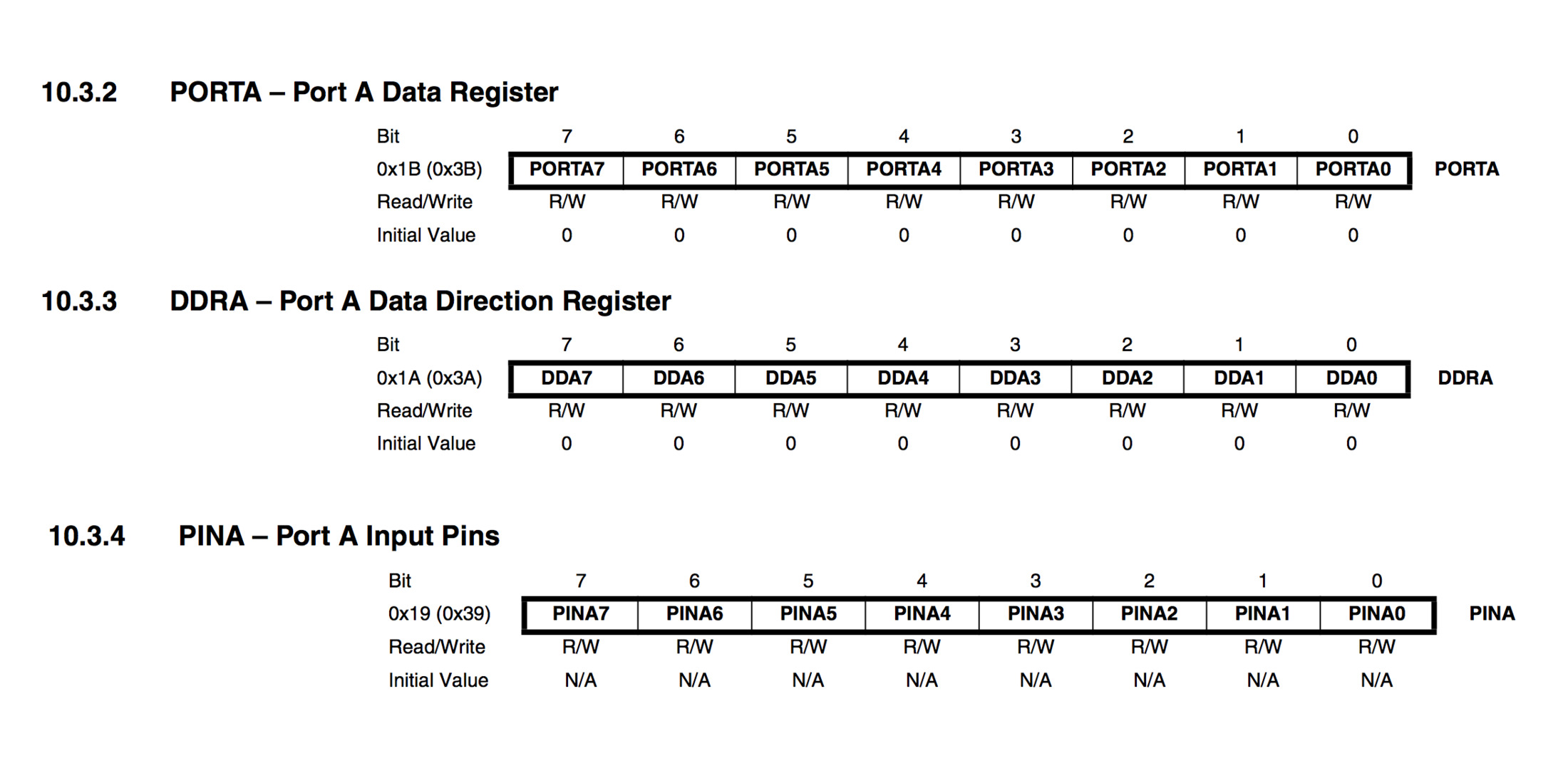
I found this tutorial particulary useful for understanding GPIO ports. Summarizing the tutorial: It is important to understand that to change setting for one single pin of the port, you have to change a particular bit in associated register. All its ports are 8 bit wide, every port has 3 registers associated with it each one with 8 bits and every bit in those registers configure pins of particular port. These three registers are:
- DDRA register. Configures data direction of port pins. Writing 0 to a bit in DDRA makes corresponding port pin as input, while writing 1 to a bit in DDRA makes corresponding port pin as output.
- PINA register. Used to read data from port pins. In order to read the data from port pin, first you have to change port’s data direction to input. If port is made output, then reading PINx register will give you data that has been output on port pins
- PORTA register. Used for two purposes:
- To output data when port is configured as output. Corresponding pins becomes output pins. Now you can write data into respective bits in PORTA register. This will immediately change state of output pins according to data you have written
- activate/deactivate pull up resistors – when port is configures as input. When you set bits in DDRA to 0, then corresponding bits in PORTA register are used to activate/deactivate pull-up registers associated with that pin. In order to activate pull-up resister, set bit in PORTA to 1, and to deactivate set it to 0.
- In input mode, when pull-up is enabled (PORTA is 1) default state of pin becomes ‘1’. So even if you don’t connect anything to pin and if you try to read it, it will read as 1. Now, when you externally drive that pin to zero, only then it will be read as 0.
- if you configure pin as tri-state (PORTA is 0). Then pin goes into state of high impedance. In this case, if pin is left floating (i.e. kept unconnected) then even small static charge present on surrounding objects can change logic state of pin. If you try to read corresponding bit in pin register, its state cannot be predicted.
Regarding the motor driver,The A4953 overcurrent protection can only be reset by putting the device into standby mode or by cycling the power to VBB. In order to use PWM current control –page 7 of the A4953 Datasheet– a low-value resistor is placed between the LSS pin and ground for current sensing purposes.
The control truth table and timing diagram, describes how the signal needs to be formed. In my code I am just driving the motor forward (IN1=0, IN2=1) for a determined ammount of time. Then braking the motor (IN=1, IN2=2). And finally, driving the motor in reverse (IN1=1, IN2=0). Note that as explained in this tutorial,Slow, mixed and fast decay modes in detail, you cant change from foward to reverse directly as driver will protect itselff from the inductive load generated by the motor, for this reason you need to brake first –a mere 15 microseconds will suffice– before driving the motor to the opposite direction.
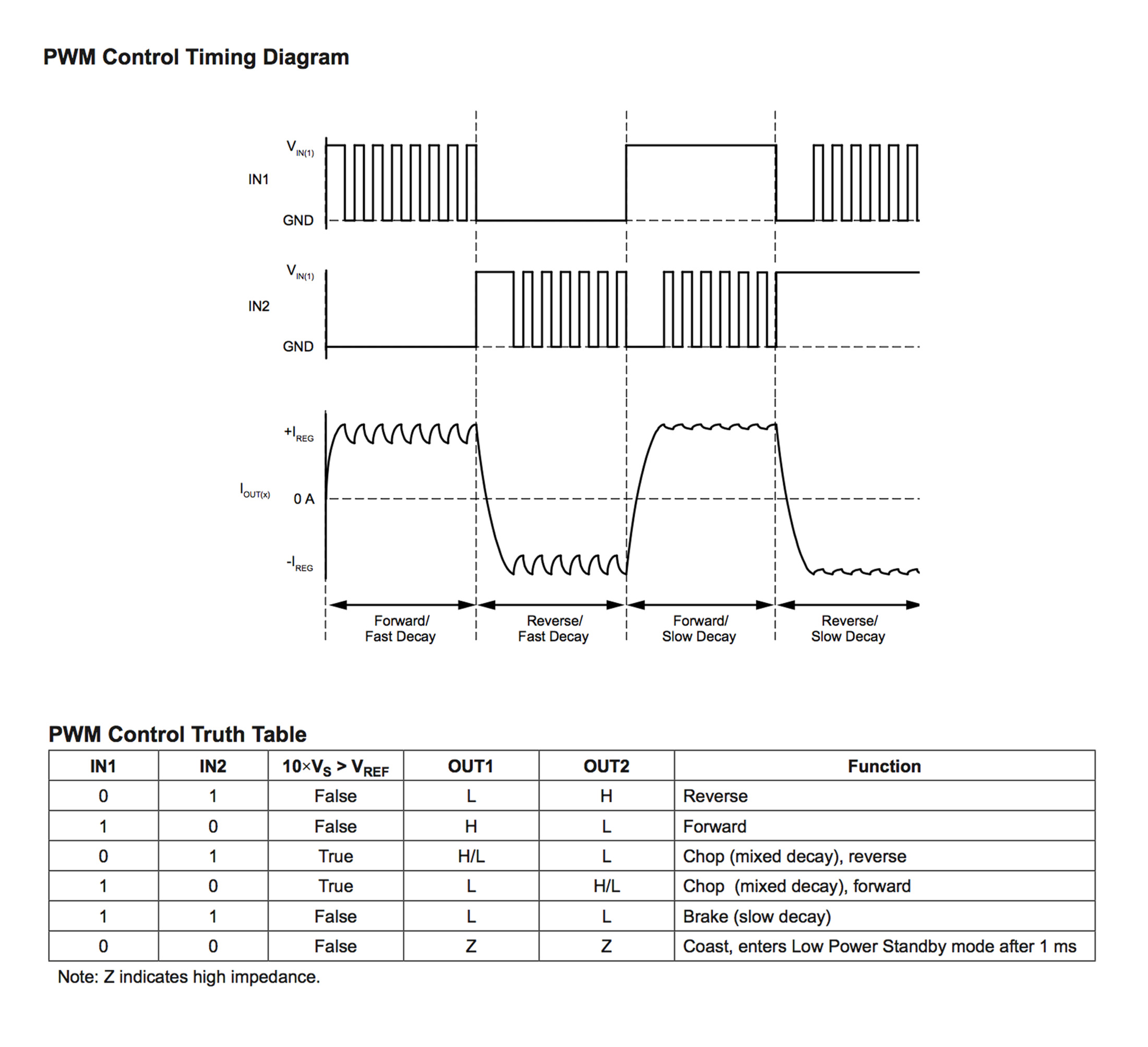
This is my final code and below the video showing the resulting behaviour:
//
// DC.H-bridge.c
//
// http://www.nongnu.org/avr-libc/user-manual/group__avr__io.html
#include
// http://www.nongnu.org/avr-libc/user-manual/group__util__delay.html
#include

// The | operator compares each binary digit across two integers and gives back a 1 if either of them are 1
#define output(directions,pin) (directions |= pin) // set port direction for output. directions = directions | pin
#define set(port,pin) (port |= pin) // set port pin
// The & operator compares each binary digit of two integers and returns a new integer, with a 1 wherever both numbers had a 1 and a 0 anywhere else
#define clear(port,pin) (port &= (~pin)) // clear port pin

// 10.1.1 Configuring the Pin
#define bridge_port PORTA // H-bridge port
#define bridge_direction DDRA // H-bridge direction
#define IN1 (1 << PA3) // IN1
#define IN2 (1 << PA2) // IN2

int main(void) {
   // CLKPR Clock Prescale Register 6.5.2 attiny44 and table 6-11
   // To avoid unintentional changes of clock frequency, a special write procedure must be followed to change the CLKPS bits:
   // 1. Write the Clock Prescaler Change Enable (CLKPCE) bit to one and all other bits in CLKPR to zero.
   // 2. Within four cycles, write the desired value to CLKPS while writing a zero to CLKPCE.
   // set clock divider to /1
   // CLKPR = 0b0000000 CLKPR = 0b1000000 (1 << CLKPCE) The << operator shift number 1 seven places to the left
   CLKPR = (1 << CLKPCE);
   // The | operator compares each binary digit across two integers and gives back a 1 if either of them are 1
   CLKPR = (0 << CLKPS3) | (0 << CLKPS2) | (0 << CLKPS1) | (0 << CLKPS0);
   //
   // initialize H-bridge pins
   //
   clear(bridge_port, IN1);
   output(bridge_direction, IN1);
   clear(bridge_port, IN2);
   output(bridge_direction, IN2);
   //
   // main loop
   //
    while (1) {
     clear(bridge_port, IN1);
     set(bridge_port, IN2);
     _delay_ms(3000);
     set(bridge_port, IN1);
     set(bridge_port, IN2);
     _delay_ms(15);
     set(bridge_port, IN1);
     clear(bridge_port, IN2);
     _delay_ms(3000);
    }
 }
Thirteenth task
Input
This week task is to add a sensor to a microcontroller board that you have designed and read it. I will use this week task to work on my final project and read a IR visible phototransistor. I will research the two applications explained at the class. First, using the phototransistor so I can sense the amount of light and activate the roller blinds if necessary. Second, use the light reflect technique so I could potentially use the same phototransistor as end stop switches for the roller blind
I will be using a phototransistor as the sensor, specifically the PT15-21C/TR8The device is Spectrally matched to visible and infrared emitting diode and in the datasheets they recommend to be carefully when soldering as a high temperature soldering iron tip can damage the sensor.
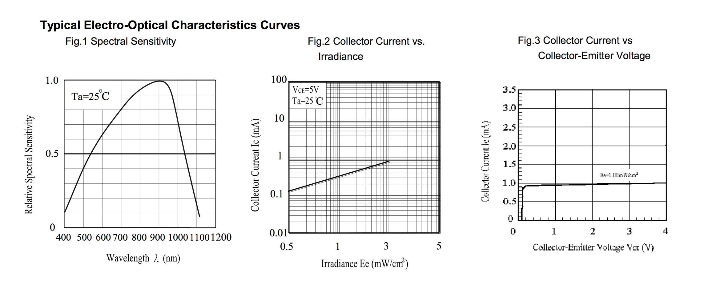
Afer doing some research on ambient light sensors, I am still not sure if the PT15-21C/TR8 will be the right one for the first applications that I have in mind –sensing if there is too much sun radiation so I can roll down the blinds– In this article some of the characteristics of these type of sensors are explained. These sensors have experienced an intense development as they are key components to adjust brightness of mobile devices in exterior environments. These sensors try to mimic the spectral sensitivity of the human eye.
Designing the board
As I would need to do several different test, this week I decided to do a board with more potential functionality than previous weeks. I based my board on hello.reflect.45 but adapted to use a ATtiny44 instead of the ATtinty45 so I can have additional pins for testing out different sensors configurations. I also decided to add a 20MHz crystal in case I want to improve the clock precision of the board when transmitting data via the FTDI port.
I also added a 4 pin external connector to attach a remote phototransistor sensor. In this way, I will be able to measure the signal noise caused by long cables when sensing the ambient light at different points of the window.
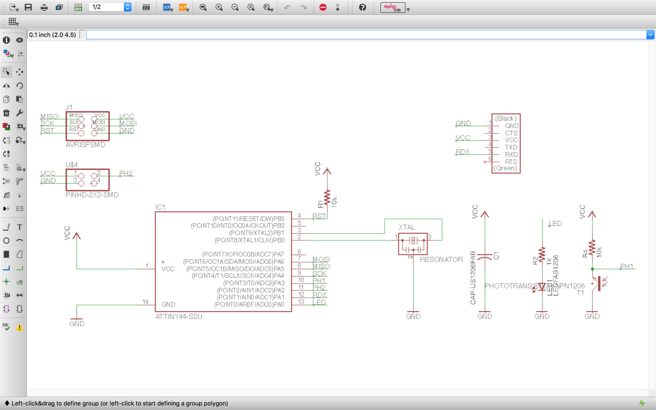
Once the schematic is ready is time for the board design. Having to design new boards each week is great for getting comfortable with this process. As more pins are used and new boards have more components and functionality the design becomes harder.
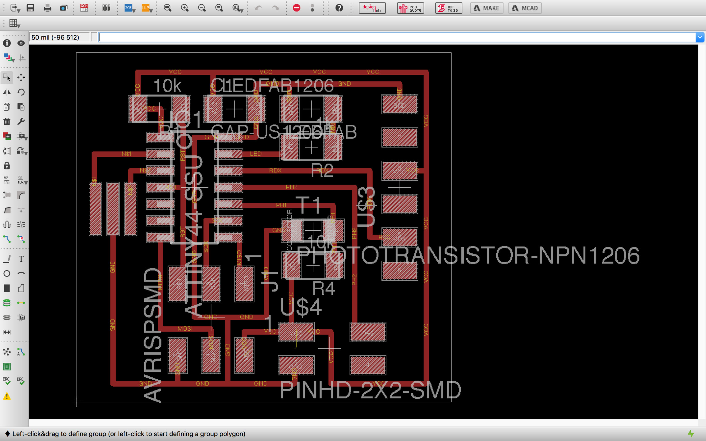
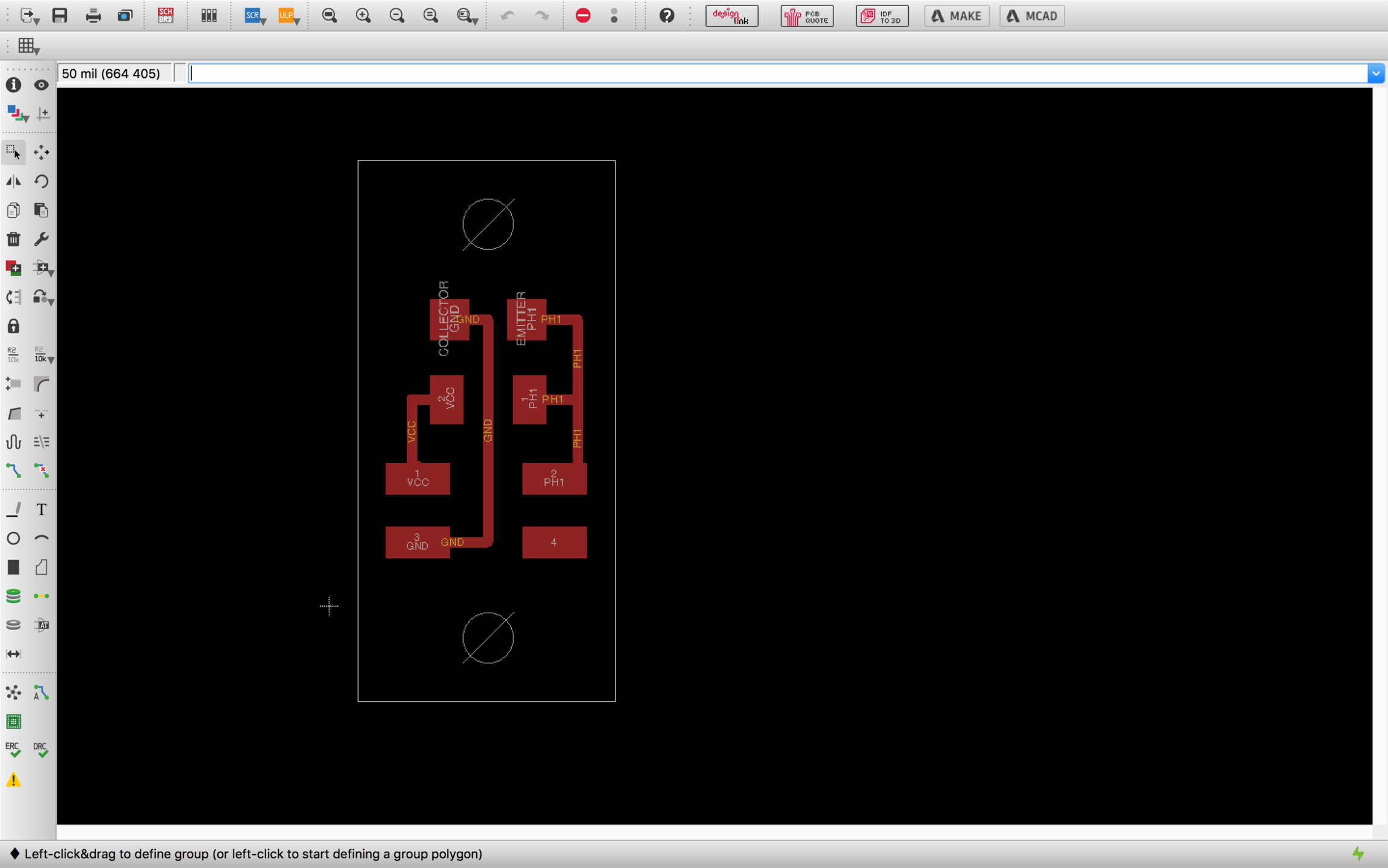
As said before, I decided to make an auxiliary board which will work as a remote phototransistor sensor for testing purposes. If the signal noise ratio is not acceptable I will have to include a microprocessor on each sensor board, do the analog to digital conversion near the sensor and transmit the readings digitally.
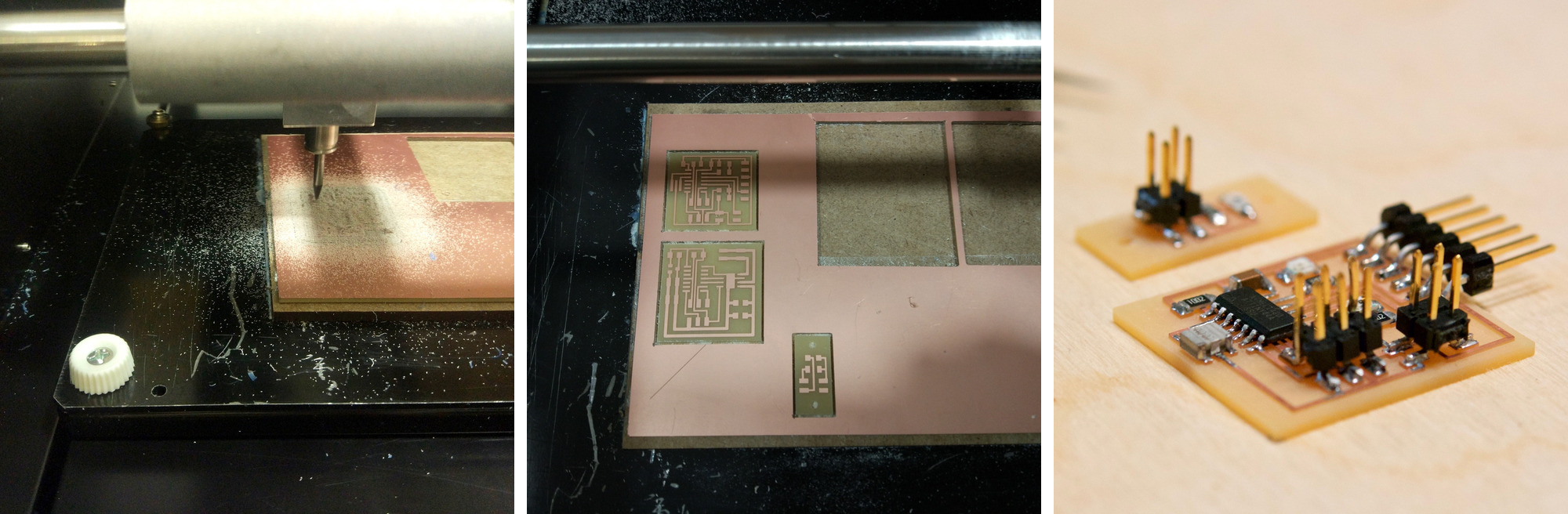
Fabricating the board
The fabrication process went without much problems. Cutting both boards and soldering all the components was a smooth an increasingly enjoyable process.
Programming and testing
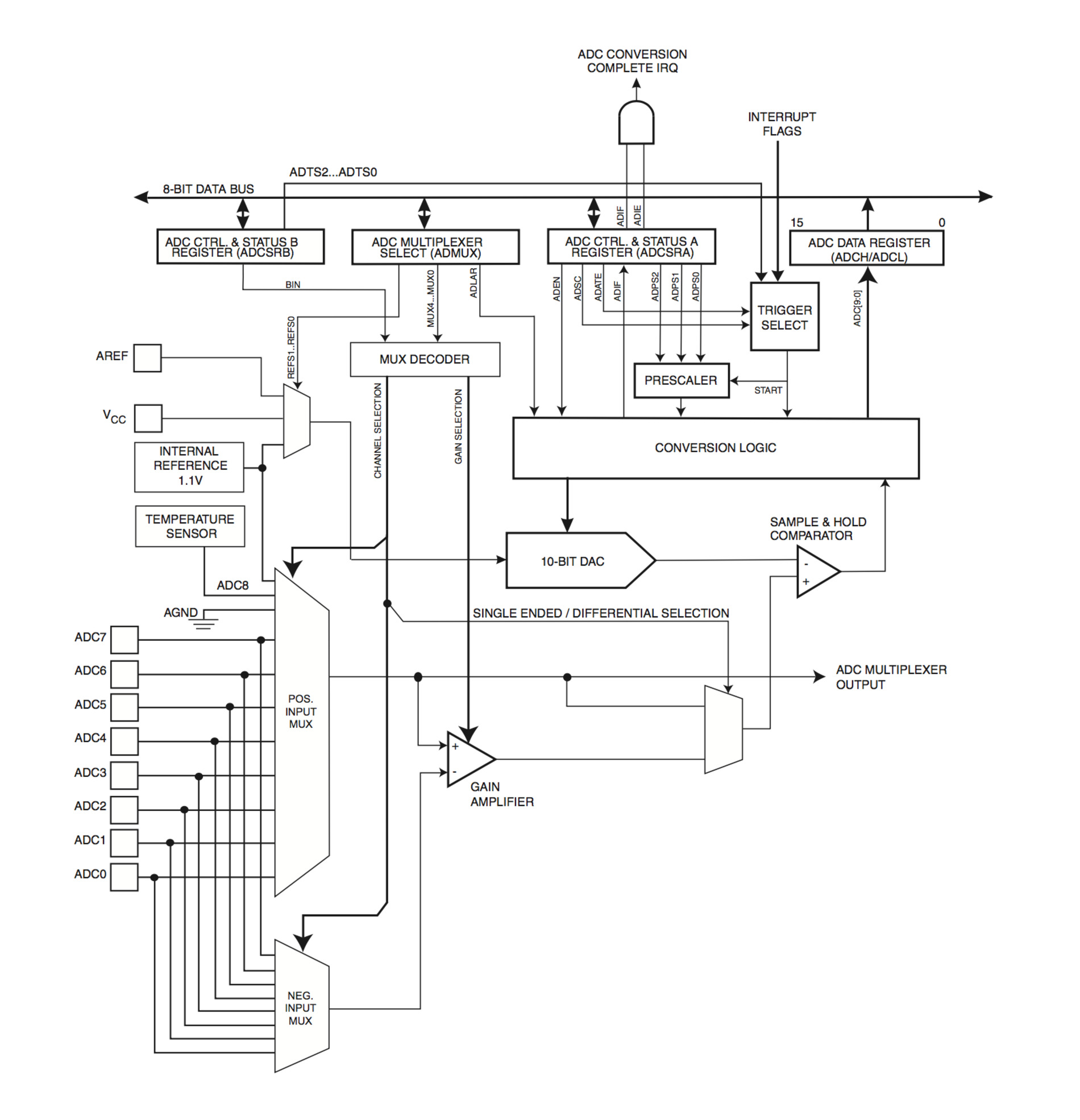
The analog digital converter converts an analog voltage to a 10-bit digital value. The minimun voltage represents GND and the maximun value represents the reference voltage. We can select between three different voltages by writing to the REFS1 and REFS0 bits in the ADMUX registry: internal 1.1v, VCC supply or use the AREF pin. The analog input channel are selected by writing to the MUX5:0 bits in ADMUX. The ADC can also be used for differential measurements
The ADC generates a 10-bit result which is presented in the ADC Data Registers, ADCH and ADCL. If the result is left adjusted and no more than 8-bit precision is required, it is sufficient to read ADCH. A single conversion is started by writing a logical one to the ADC Start Conversion bit, ADSC. This bit stays 1 as long as the conversion is in progress and will be cleared by hardware when the conversion is completed.
I will be programming first the proximity sensing feature using the synchronous detection technique. The principle is that you get a number of samples from the light sensor switching on and off an adjacent led so you get a modulated signal on top of the analog signal, by doing this you can measure the relative amount of light with significant precision. I am using hello.reflect.45.c as the reference, commented code below:
//
// week13-inputlight.44.c
//
#include
#include

#define output(directions,pin) (directions |= pin) // set port direction for output
#define set(port,pin) (port |= pin) // set port pin
#define clear(port,pin) (port &= (~pin)) // clear port pin

#define pin_test(pins,pin) (pins & pin) // test for port pin
#define bit_test(byte,bit) (byte & (1 << bit)) // test for bit set

#define bit_delay_time 102 // bit delay for 9600 with overhead
#define bit_delay() _delay_us(bit_delay_time) // RS232 bit delay
#define half_bit_delay() _delay_us(bit_delay_time/2) // RS232 half bit delay
#define char_delay() _delay_ms(10) // char delay

#define serial_port PORTA    // RS232 serial output
#define serial_direction DDRA
#define serial_pin_out (1 << PA1)

#define led_port PORTA     // led output
#define led_direction DDRA
#define led_pin (1 << PA0)

#define nloop 100 // number of loops to accumulate

void put_char(volatile unsigned char *port, unsigned char pin, char txchar) {
   //
   // send character in txchar on port pin assumes line driver (inverts bits)
   //
   // start bit
   // port, *port = contenido address = serial_port
   clear(*port,pin);
   bit_delay();
   //
   // unrolled loop to write data bits
   // Con Bit_test comprueba para cada bit del byte txchar 0,1,2...7
   // if equal to 1 then SET otherwise CLEAR
   if bit_test(txchar,0)
      set(*port,pin);
   else
      clear(*port,pin);
   bit_delay();
   if bit_test(txchar,1)
      set(*port,pin);
   else
      clear(*port,pin);
   bit_delay();
   if bit_test(txchar,2)
      set(*port,pin);
   else
      clear(*port,pin);
   bit_delay();
   if bit_test(txchar,3)
      set(*port,pin);
   else
      clear(*port,pin);
   bit_delay();
   if bit_test(txchar,4)
      set(*port,pin);
   else
      clear(*port,pin);
   bit_delay();
   if bit_test(txchar,5)
      set(*port,pin);
   else
      clear(*port,pin);
   bit_delay();
   if bit_test(txchar,6)
      set(*port,pin);
   else
      clear(*port,pin);
   bit_delay();
   if bit_test(txchar,7)
      set(*port,pin);
   else
      clear(*port,pin);
   bit_delay();
   //
   // stop bit
   //
   set(*port,pin);
   bit_delay();
   //
   // char delay
   //
   bit_delay();
   }

int main(void) {
   //
   // main
   //
   static unsigned char count;
   static uint16_t on,off;
   //
   // set clock divider to /1
   //
   CLKPR = (1 << CLKPCE);
   CLKPR = (0 << CLKPS3) | (0 << CLKPS2) | (0 << CLKPS1) | (0 << CLKPS0);
   //
   // initialize output SERIAL and output LED pins
   //
   set(serial_port, serial_pin_out);
   output(serial_direction, serial_pin_out);

   set(led_port, led_pin);
   output(led_direction, led_pin);
   //
   // init A/D
   // ADC Analog Digital Converter
   // ADMUX – ADC Multiplexer Selection Register
   ADCSRB = (0 << ADLAR); // 16.13.4 The ADLAR bit affects the presentation of the ADC conversion result in the ADC Data Register
   ADMUX = (0 << REFS1) | (0 << REFS0) // 16.13.1 VCC used as Voltage Reference
      | (0 << MUX4) | (0 << MUX3) | (0 << MUX2) | (1 << MUX1) | (1 << MUX0); // Table 15.1 The value of these bits selects which combination of analog inputs are connected to the ADC 00011 = ADC3
   // – ADC Control and Status Register A
   ADCSRA = (1 << ADEN) | (1 << ACME) // enable (Writing this bit to one enables the ADC)
      | (1 << ADPS2) | (1 << ADPS1) | (1 << ADPS0); //  ADPS[2:0]: ADC Prescaler Select Bits: prescaler /128
      // These bits determine the division factor between the system clock
      // frequency and the input clock to the ADC
   //
   // main loop
   //
   while (1) {
      //
      // accumulate
      //
      on = 0;
      off = 0;
      for (count = 0; count < nloop; ++count) {
         //
         // LED off
         //
         clear(led_port, led_pin);
         //
         // initiate analog to digital conversion
         //
         ADCSRA |= (1 << ADSC); // 16.4 Start Conversion
                                // Register ADCSRA: ADC Control and Status Register A
                                // Bit ADSC: ADC Start Conversion,
                                // In Single Conversion mode, write this bit to one to start each conversion.
         // wait for completion: ADSC will read as one as long as a conversion is in progress.
         // When the conversion is complete, it returns to zero.
         // Writing zero to this bit has no effect.
         //
         while (ADCSRA & (1 << ADSC));
         //
         // save result
         //
         off += ADC;
         //
         // LED on
         //
         set(led_port, led_pin);
         //
         // initiate conversion
         //
         ADCSRA |= (1 << ADSC);
         //
         // wait for completion
         //
         while (ADCSRA & (1 << ADSC))
            ;
         //
         // save result
         //
         on += ADC; // on = on + ADC
         }
      //
      // send framing
      //
      put_char(&serial_port, serial_pin_out, 1);
      char_delay();
      put_char(&serial_port, serial_pin_out, 2);
      char_delay();
      put_char(&serial_port, serial_pin_out, 3);
      char_delay();
      put_char(&serial_port, serial_pin_out, 4);
      char_delay();
      //
      // send result
      //
      put_char(&serial_port, serial_pin_out, (on & 255)); // toma el LSB (least significant byte) 0b1111 1111
      char_delay();
      put_char(&serial_port, serial_pin_out, ((on >> 8) & 255)); // toma el MSB
      char_delay();
      put_char(&serial_port, serial_pin_out, (off & 255));
      char_delay();
      put_char(&serial_port, serial_pin_out, ((off >> 8) & 255));
      char_delay();
      }
   }
Porting from ATtiny45 to ATtiny44 requires further study of ATtiny44 datasheets, specifically chapter 16 for the Analog to Digital Converter and its multiplexed input.
First part of the code some macros are created for assigning bit on specific pins, number of sampling cycles, and four different delays to make sure that serial communication is sent at the right speed
Then the put_char function is created, this will send the ADC digital signal as a 8-bit byte through the serial port. This function uses a coding feature that I didn't know called Pointers, this allow the function to get the value stored in memory address of the serial port without the need of creating a global variable.
Inside the main loop, first we set the clock resolution, then we initialize the output pins for the serial interface and the led. After that, we initialize the Analog to Digital Converter Multiplexer which is a device to select one of several inputs and forward the selected input to a single line. The multiplexeer is different in the ATtinty45 and ATtiny44 so it is important to read carefully sections 16.13.1 and 16.13.4 and table 15.1 to assign the right bit to the ADMUX register
Finally, in the main loop is where the magic happens. A loop of 100 cycles is created, we switch on the led, starts the ADC conversion, wait until the conversion is done and stores the value on a variable, then we switch off the led and repeat the process. The results are being Oversampled by adding then in each cycle, this helps to reduce the noise to signal ratio. Lastly, the 100 samples of "on" and "off" values are taken, we send the signal via serial to the computer. It is worth mentioning that as we are oversampling the signal we would need to transmit 16-bit byte, this is done at the end of the code by splitting the value into two 8-bit bytes and send one after the other.
The python script receives the data from the serial port and plots it. I just took the original python script from the example. There is a header data signal –1,2,3,4– to tell the python script to read the data right after that using the 8-bit packets approach described.
Below is a video in which you can watch the sensor in action. As soon as the finger approximates to the sensor the differential value between the on and off states spikes. If I have more time in the following weeks I would like to explore other configurations like using the board as just an ambient light sensor, measuring potential noise of the remote sensor and giving a try to the ADC comparator module of the ATtiny.
Sixteenth task
Write an application
This week task is to make an application that interfaces with an input and/or output device that you made. I decided to make an application that will allow to move up and down the roller blind of the window so in addition to an automated control based on the amount of light I can also control the window shade manually.
I am very interested on the idea that each component in a house is a self-autonomous node which could sense, react and communicate with other nodes. So instead of thinking in a custom mobile app to control as it is done lately with many IoT devices, I was more interested in a node running a web server with a HTML user interface and extend it with other web based technologies in the future.
Application
I wanted to try as many technologies as possible but I had limited time this week so I decided to work on a simple solution and try more things once I get the basics working.
My initial solution will be a JavaScript node.js server which will talk to my device –last week dcmotor board with input and output ports– via serial interface then a HTML form on top of bootstrap will talk to the server via websockets.
The user interface
For the user interface I decided to go for the most compatible standard, HTML forms. In theory, I will be able to control the window from almost any device, a screen reader or a old phone from example. In order to improve the look and feel of the buttons I choose to use bootstrap, a great framework for creating responsive HTML interfaces. You can find all the documentation here.
HTML below is the user interface, if you are using a computer not connected to internet as a server you will need to download bootstrap locally and point to the local css file instead.
Fabwindow · Roller blind control
Fabwindow Roller blind control
Webserver
For the web server I will be using JavaScript and node.js. Node package manager for JavaScript, I will be using three different elements on the webserver: Express a lightweight webframework to create web applications in node.js, Serialport, a node package to communicate with hardware via serial and Websocket a JavaScript implementation of the websocket protocol to connect my webserver with the HTML User Interface
NPM is a really convenient way of managing all these construction blocks, you just need to make sure to add a package.json file with the packages that you wish to use and their version requirements. Once you run npm install, npm will look for the right versions and install them locally. You can lock, update and use different versions of the package in each of your projects so it makes much more simpler to maintain code.
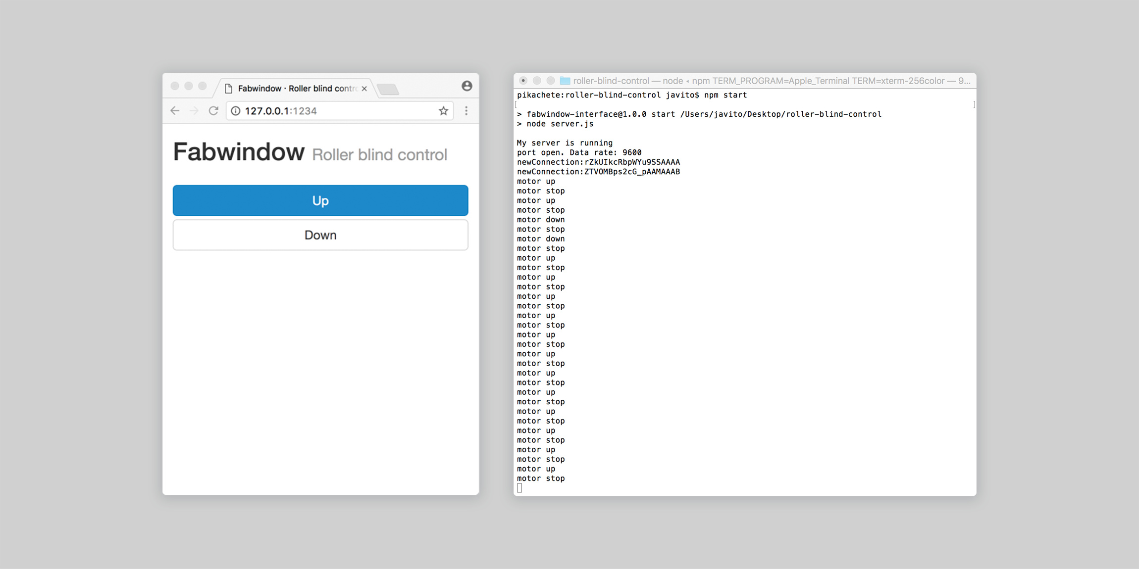
The server's code is no more than 70 lines of code. First, we create an express web app listening to a specific IP port, then we create a serial connection with our hardware device specifying the serial port address and baud rate. Third, we establish a websocket connection once the browser points to the right IP and port address and wait for the information send by the HTML form in the browser, if the information matches the intended messages we send different bytes through the serial port and the console for debugging purposes –three different messages 'u' for motor up, 'd' for motor down and 's' for motor stop–. Finally, a series of auxiliary functions send messages to the console to make sure that connection with the browser and hardware devices are occurring.
//
// server.js
//
var express = require('express');
var app = express();
var server = app.listen(1234);
app.use(express.static('public'));
console.log("My server is running");

var socket = require('socket.io');
var io = socket(server);
io.sockets.on('connection', newConnection);

function newConnection(socket){
	console.log('newConnection:' + socket.id);
	socket.on('led', ledMsg);
	function ledMsg(data){
		if (data=='u'){
			myPort.write(data);
			console.log('motor up');
		}
		if (data=='s'){
			myPort.write(data);
			console.log('motor stop');
		}
		if (data=='d'){
			myPort.write(data);
			console.log('motor down');
		}
	}
}

var SerialPort = require('serialport');
var myPort = new SerialPort("/dev/cu.usbserial-FTFMJ7FE", {
	baudRate: 9600,
	options: false,
	parser: SerialPort.parsers.readline("\n")
});

myPort.on('open', showPortOpen);
myPort.on('close', showPortClose);
myPort.on('error', showError);

function showPortOpen() {
   console.log('port open. Data rate: ' + myPort.options.baudRate);
}

function showPortClose() {
   console.log('port closed.');
}

function showError(error) {
   console.log('Serial port error: ' + error);
}
User interface javascript
Now we need to add the functionality to the HTML interface to communicate with the webserver, with the code above the HTML interface doesn't know yet how to communicate with the server.
First, we need to establish a websocket connection to the same address and port in which the web server is listening to. Second, we need to add the different functions that will be triggered by the button elements onpress and onrelease events –statusUp(), statusDown() and statusStop() respectively–
Fabwindow · Roller blind control
Fabwindow Roller blind control
Device programming
The last part would be to program the device to switch on and off the motor driver inputs and control the DC motor based on the three different commands sent via the serial port: Up, down and stop.
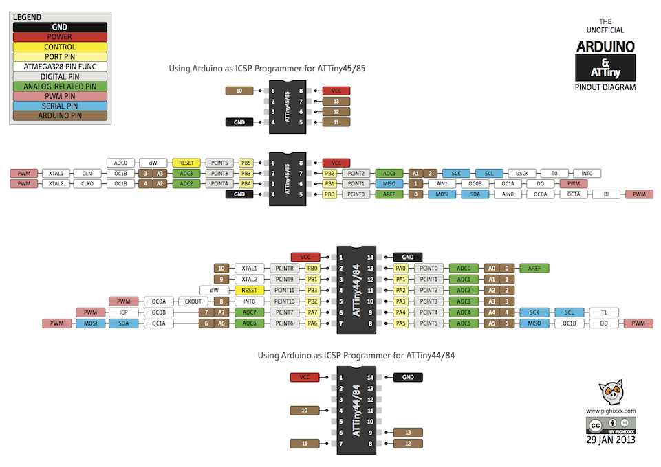
I will be using the Arduino library and IDE for the first time since Week 8. First thing I noticed is that Arduino pinout numbering doesn't match Attiny data sheets, luckily there is plenty of information on the internet about this. I found this great visual cheat sheet of the different attiny processors pinouts:
I will be using the softwareserial library for arduino, this library is a software implementation of the serial protocol. Remember that in order to use the standard arduino hardware implementation of the serial protocol you need to use specific pins of the Attiny.
Then, I need to set up all the different variables and initialize the pins directions for the motor driver, led and serial connection.
Inside the main loop, I check if the serial is being used, if not, it reads the data and depending on the command sent it controls the motor driver up, down or stop.
#include
// only sending info from the computer
// rx 9
// tx 9
SoftwareSerial mySerial(9, 9);
const int ledPin = 7;

const int in1Pin = 1;
const int in2Pin = 0;

int buttonPushCounter = 0;
int buttonState;
int ledState;
int lastButtonState = HIGH;

void setup() {

  pinMode(in1Pin, OUTPUT);
  pinMode(in2Pin, OUTPUT);

  pinMode(ledPin, OUTPUT);

  mySerial.begin(9600);
}


void loop() {
  if (mySerial.available()>0){
    ledState = mySerial.read();
    if (ledState == 'u') {
      // motor up
      digitalWrite(in1Pin,HIGH);
      digitalWrite(in2Pin,LOW);
      // led on
      digitalWrite(ledPin,HIGH);
    } else if (ledState =='s') {
      // motor stop
      digitalWrite(in1Pin,LOW);
      digitalWrite(in2Pin,LOW);
      // led off
      digitalWrite(ledPin,LOW);
    } else if (ledState =='d') {
      // motor up
      digitalWrite(in1Pin,LOW);
      digitalWrite(in2Pin,HIGH);
      // led on
      digitalWrite(ledPin,HIGH);
    }
  }
}
Final step would be to flash the microcontroller, run the server and open the browser on the right IP and port address to initialize the websocket connection. Below the video showing all the parts working together.