Fabacademy 2017
Seventh Week. Computer-Controlled Machining
Index
Seventh task
Make something big
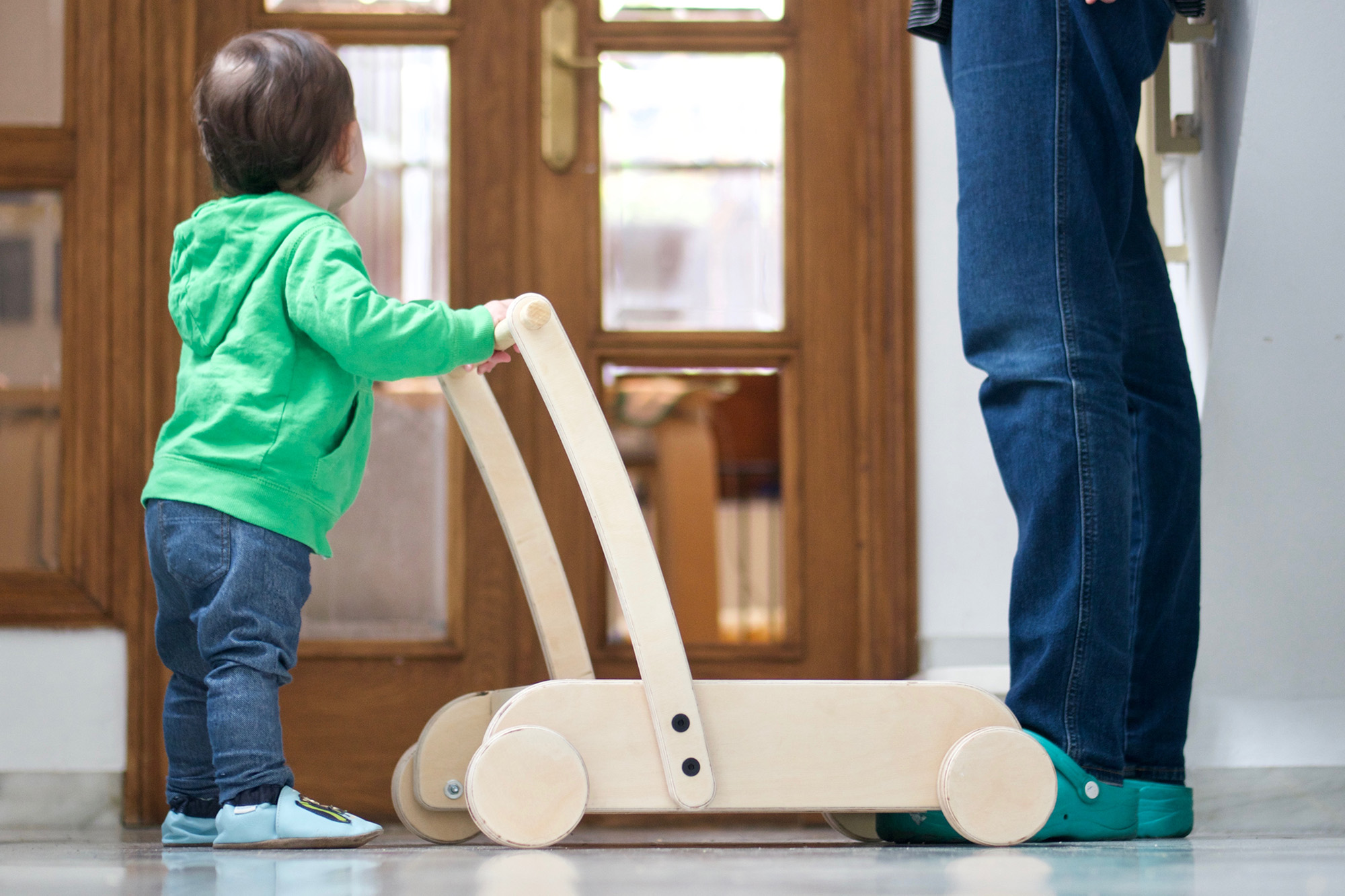
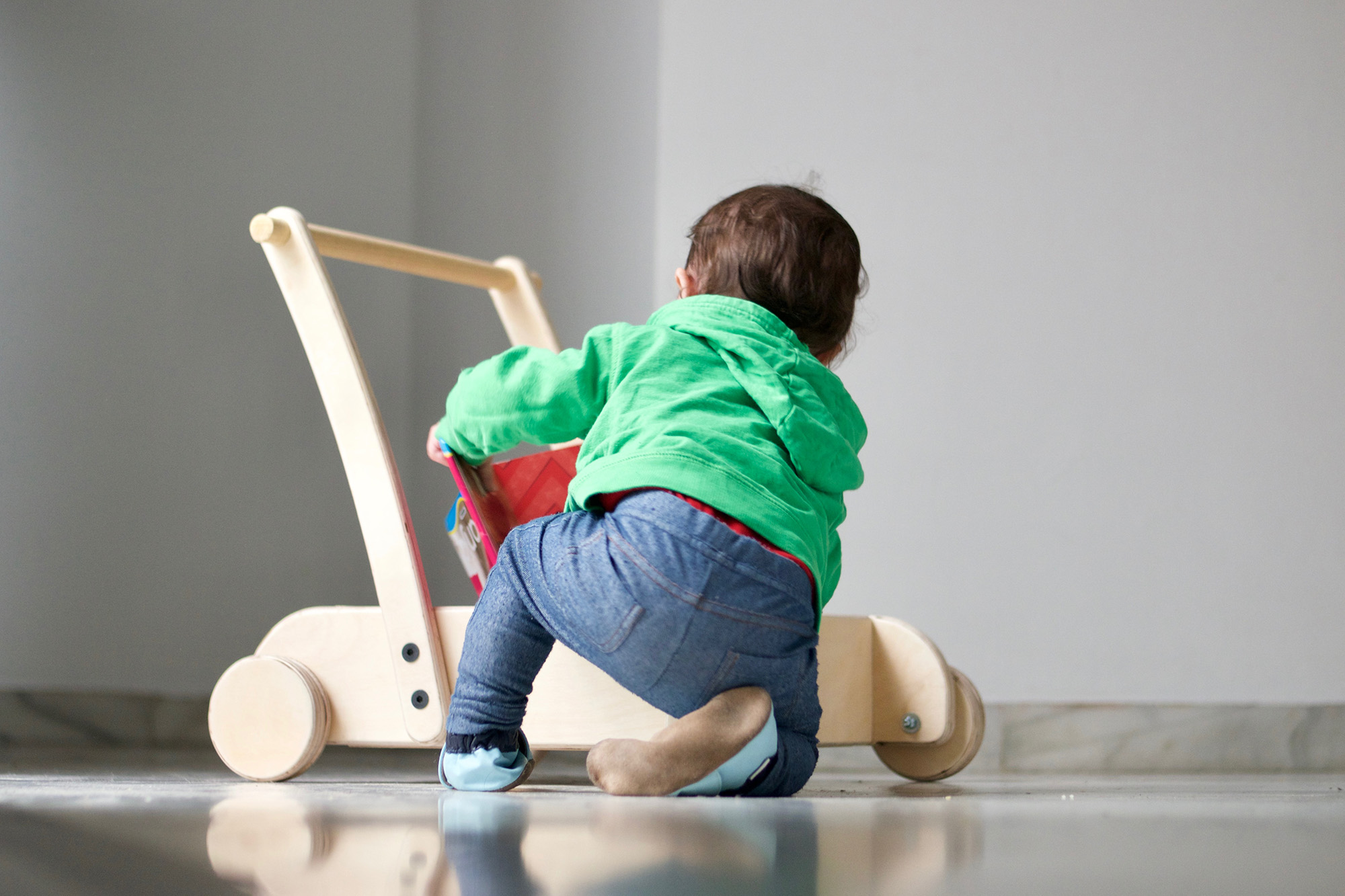
This week task is to make something big using the CNC. I'm afraid that I wont have access to the CNC as I am away from the fab lab until Friday so I decided to spend some extra time learning OnShape and parametric design to design a simple walker for my 1 year old baby which I would be able to modifiy in height and width as she grows and start using it for carrying toys.
Onshape
My experience with parametric tools has been somewhat frustrating up to now, I did try Freecad on my second week assigment but I found the interface clumsy and confusing. For the press-fit laser cut task I tried Autodesk Fusion360 but again, it didn't work for me and I end up using antimony.
After John Hirschtick recitation I got very interested about Onshape as I am looking for parametric design tools that are platform independent. I also found interesting their business model of offering free access for public projects and I was quite intrigued by the performance of running this type of software directly from the browser.
To be honest I was gladly surprise by its clean and well structured interface and the impressive performance. After a couple of tutorials it felt familiar enough to get started. I really recommend it to give it a try if you are not convince by other packages. I did find some limitations about OnShape:
- No offline mode. Despite John arguments I still do a lot of work while travelling, so not being able to use it offline can be frustrating sometimes.
- No manufacturing features. This is a common pending issue in all the parametric softwares I have tried to date. Design and fabrication are still quite disconnected, I would like to design in 3D and unpack the pieces in the stock while I am designing as well as connect to 3D printers, laser cutters and CNC directly from the software.
- Limited part drawing features. While the parametric modelling features are quite advanced, I was disappointed with the available drawing tools. It is not possible to do really basic 2D drawing operations when preparing the 2D drawing like copy, rotate or even create custom paper sizes. There are two workarounds for the last two ones. I will have a better understanding of these limitations when cutting the parts on Friday.
Baby walker
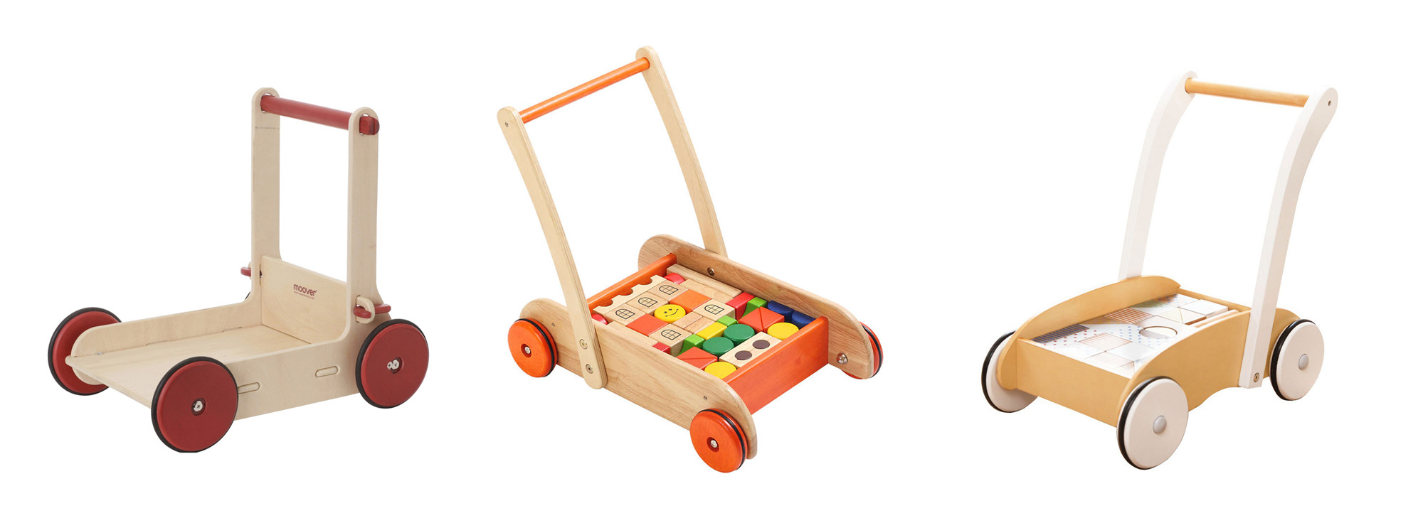
There are many types of baby walkers out there. After doing some research I narrowed down the ones that felt more adecuate. The design is based on few simple principles:
- It will use as little stock material as possible.
- Safe and stable, increased width compare with the commercial ones.
- Design will be sturdy but elegant at the same time.
- It will be ergonomic and functional, for example handle bar will be rounded, there will have loading area to carry toys around, etc…
- Design will avoid the usual CNC aesthetics as t-bones, clip or press-fit joints.
- Mechanical fixings are allowed but timber joints will be preferred.
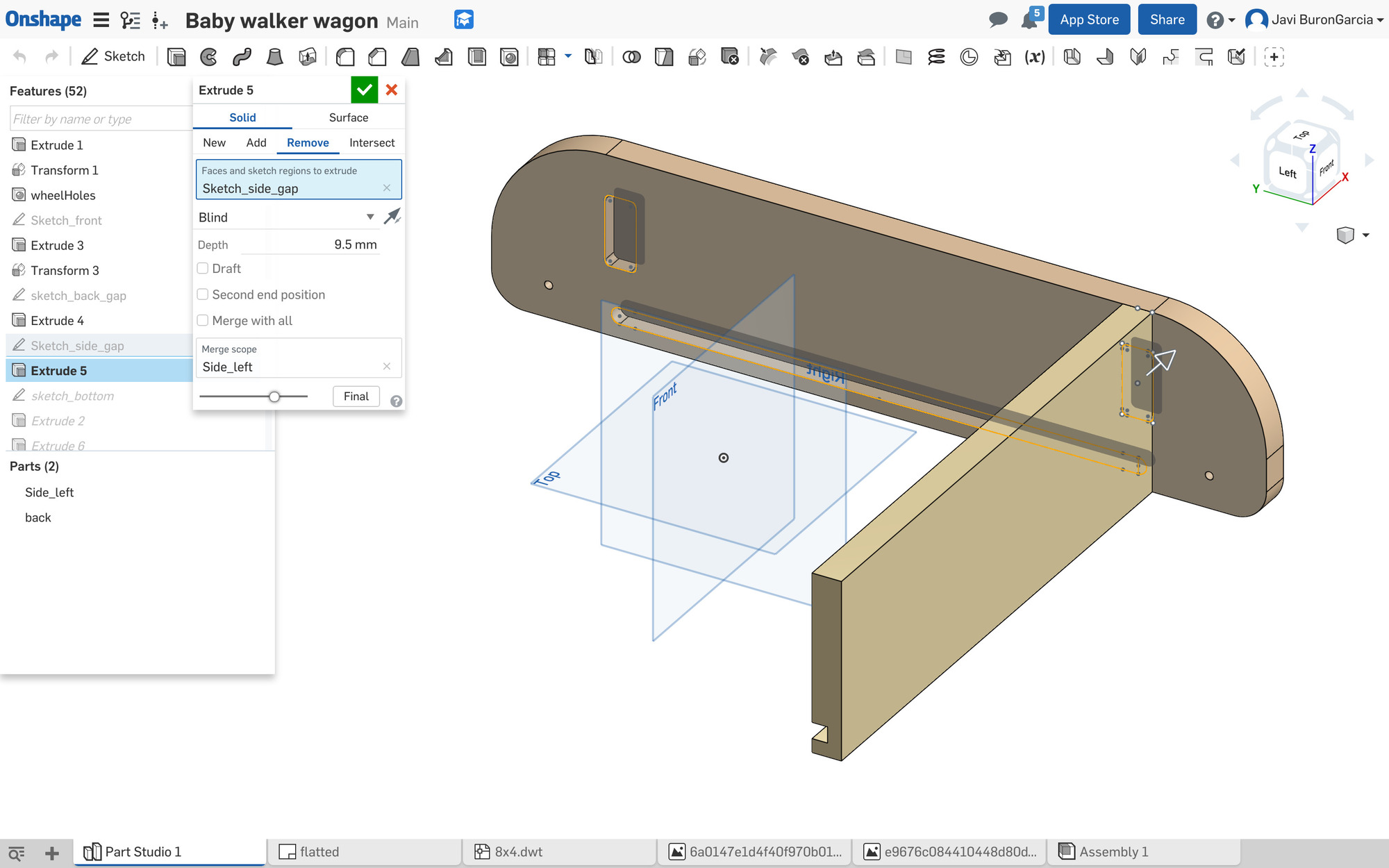
Parametric design
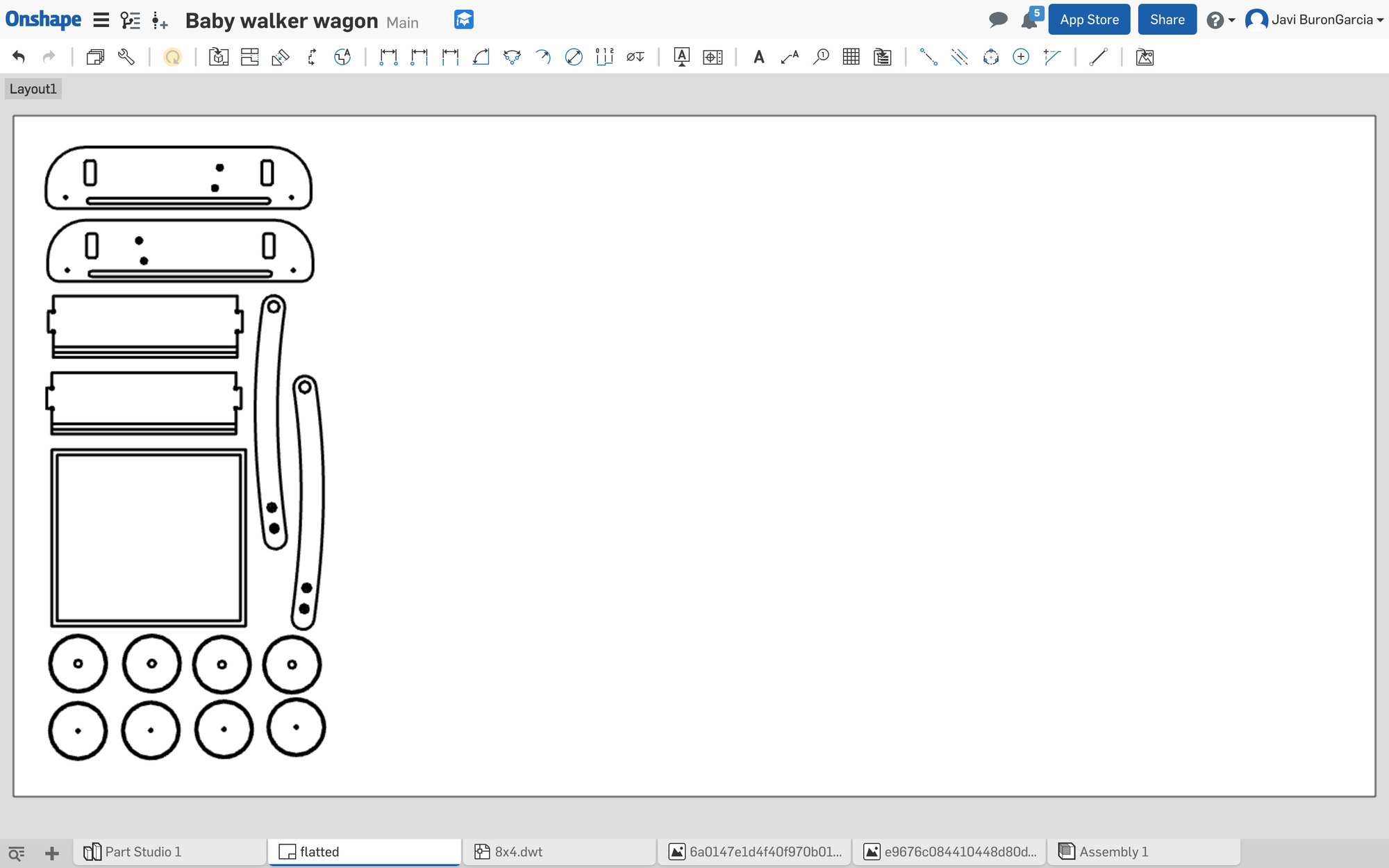
Parametric design is really the way to go when prototyping with CNC as there are several variables that will need to be adjusted during the fabrication process such as tool diameter, kerf and offset. I created those as well as variables for the stock thickness and the fixings diameter. Once you select the piece of timber that you will be using for the job, measure it with a calliper and adjust stock thickness parameter accordingly, 0.1mm variance can make a noticiable difference when assembling the parts together.
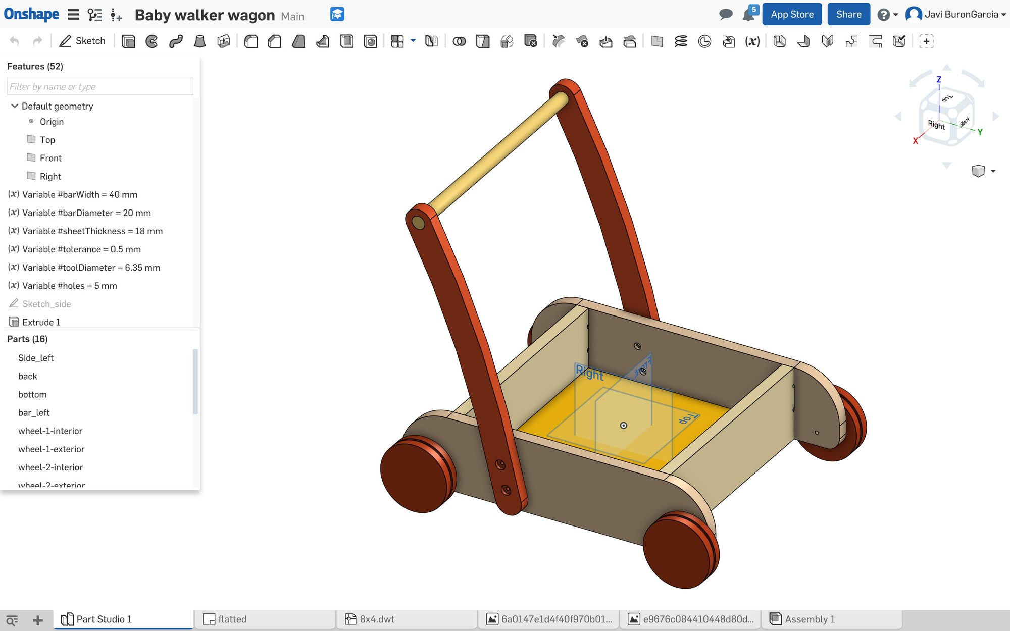
Onshape keeps every command recorded as part of the history so be careful when creating new variables during the process as they wont be able to be used in previous commands, drag and drop the variables to the top of the list for that.
Once I got all the elements designed, I created a drawing and placed all the part on a 8 by 4 foot sheet. The process for creating custom sheet sizes is not trivial and requires that you create an Autodesk Autocad template with the required sizes and then upload the dwt file into Onshape.
Cutting the design
I used a compression bit for this job, this bit combines a down cut and an up cut compressing the chips at the center and eliminating chipping on both the top and bottom of the workpiece.
| Flutes | RPM | Feed Rate | Plunge Rate | |
|---|---|---|---|---|
| 1/4" Compression | 2 | 18,000 | 1.4 ips | 1 ips |
Our Shopbot doesn't have a vacuum table so stock material does need to be screwed to the spoil board. Make sure you place the screws in areas that wont be cutted, vcarvepro simulation feature is really helpful for that.It is always recommended, specially for the first time, to set up the z origin few centimeters above the stock material and run the job "cutting air" first before zeroing the z axis correctly.
I had to cut it in two passes but making sure that the first pass was deeper than the upcut portion of the compression bit –in my case 13mm– otherwise you will get tearout on the top. in this way you still get the benefit of the compression bit, even when you cut in passes, because you will get a smooth top and bottom cut.
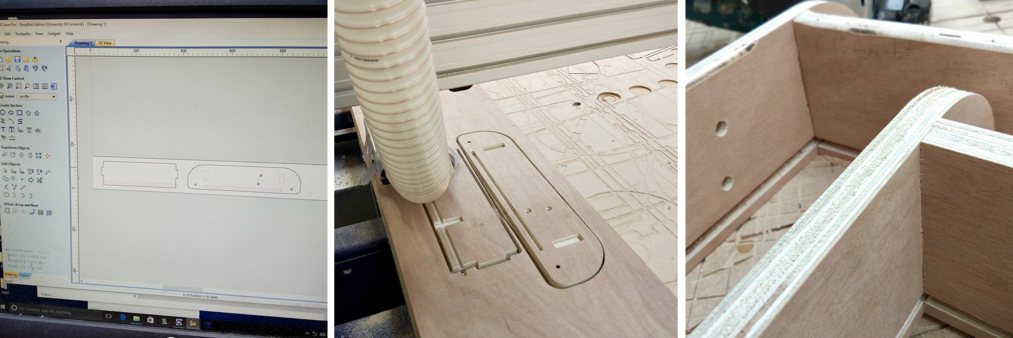
Two trials were needed to adjust tolerances and tool diameter in the design. Bit diameter was supposed to be 6.35mm (1/4 inches) but I think it was something like 6.25mm. I reduced the tolerance to just 0.1mm to get a really tight joint. I had some problems cutting trough the whole ply in some areas which could mean that the sheet or the base was warped so I decided to clean out the base by shaving 5mm of the sacrificial board.
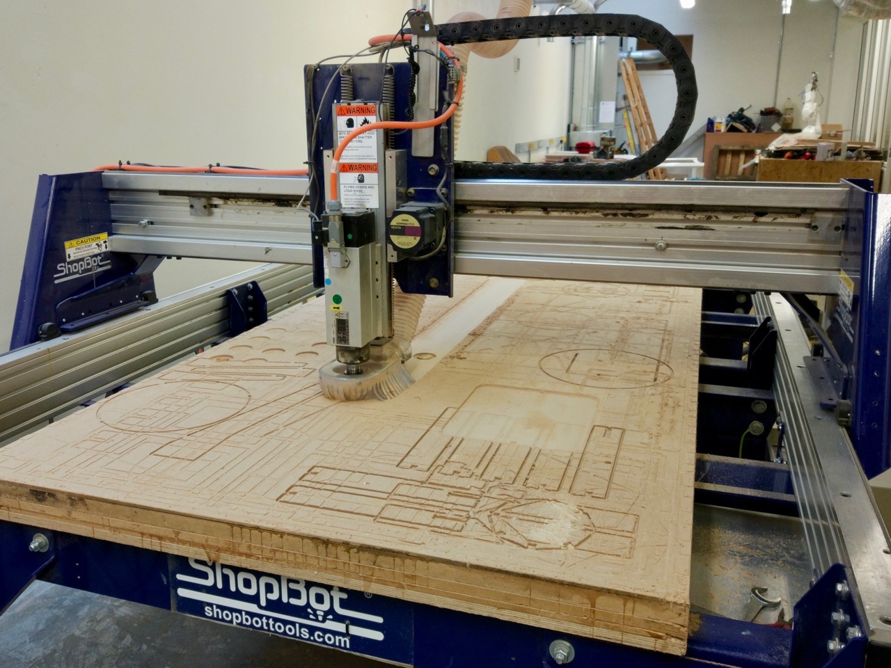
Once the base was perfectly flat, I screwed a better quality ply for my final cut. I divided the job into 9 different operations as the design uses a number of pockets of different heights and several different profile cuts.
For the profile paths I used tabs of 10mm length and 0,8mm height, I added zig zag ramps to the path. For the pocket paths also used ramps.
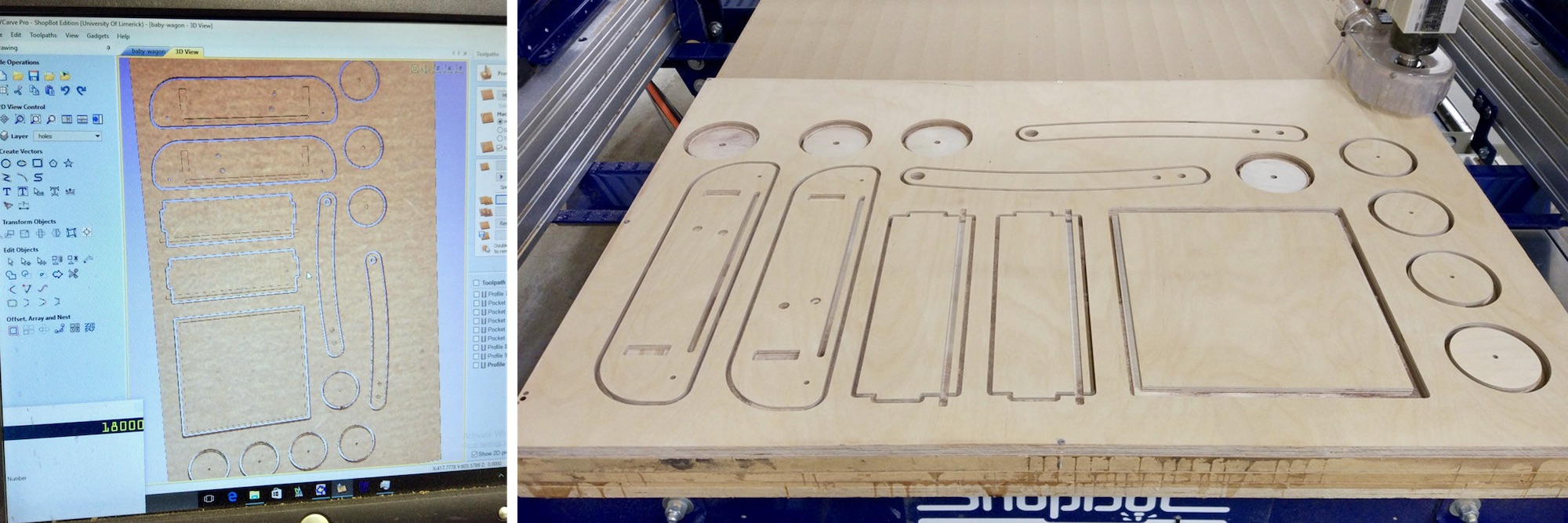
V-carve Pro has a very useful simulation preview that helped me to stage all the different operations in the right order. I had to use tabs for the final profile as parts were small and light and could move right at the end. There might be a more elegant way to solve this but it worked for now.
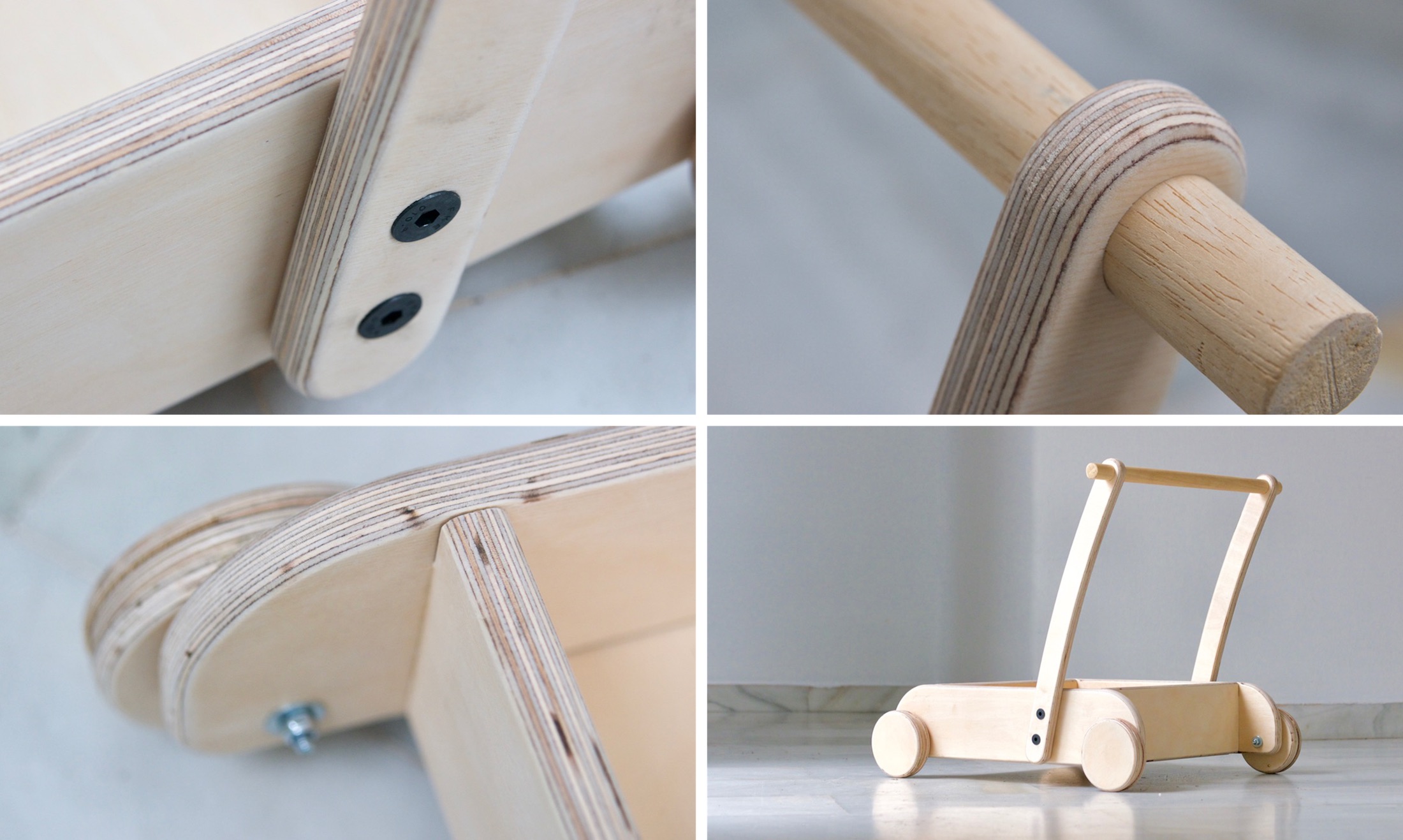
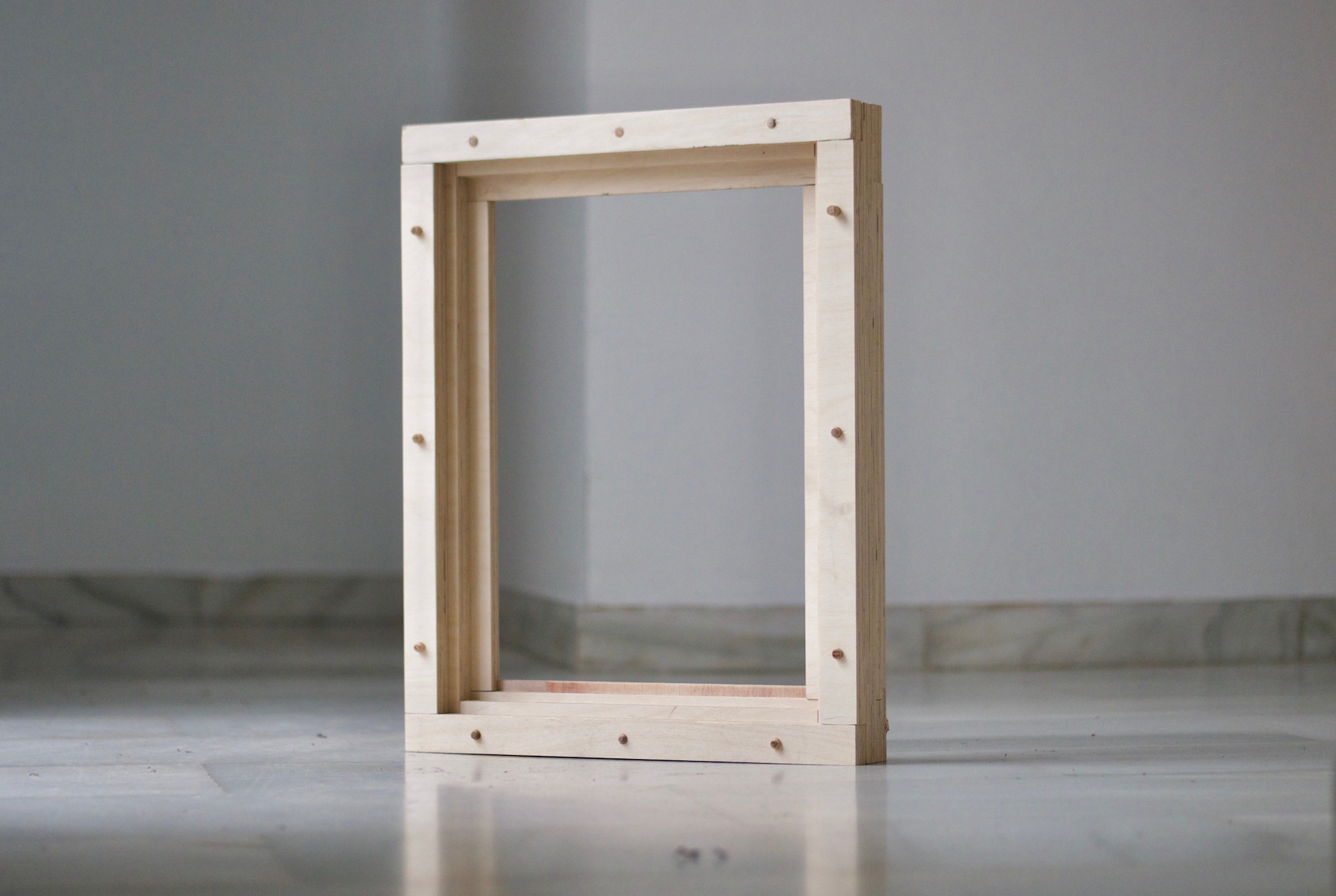
Assembly and finishes
Being a toy for a 1 year old baby I wanted to round the edges of most parts. initially I wanted to do this with the CNC but I ended up using a hand router instead. I had some issues with the rounding bit, tried to adjust speed to reduce burn marks but I think the bit was quite worn out. Assembly took less than an hour. I still need to paint, varnish and source four 100mm diameter toroidal sealing rings for the wheels before considering it completely finish but it seems that my client is quite happy with the results so far!

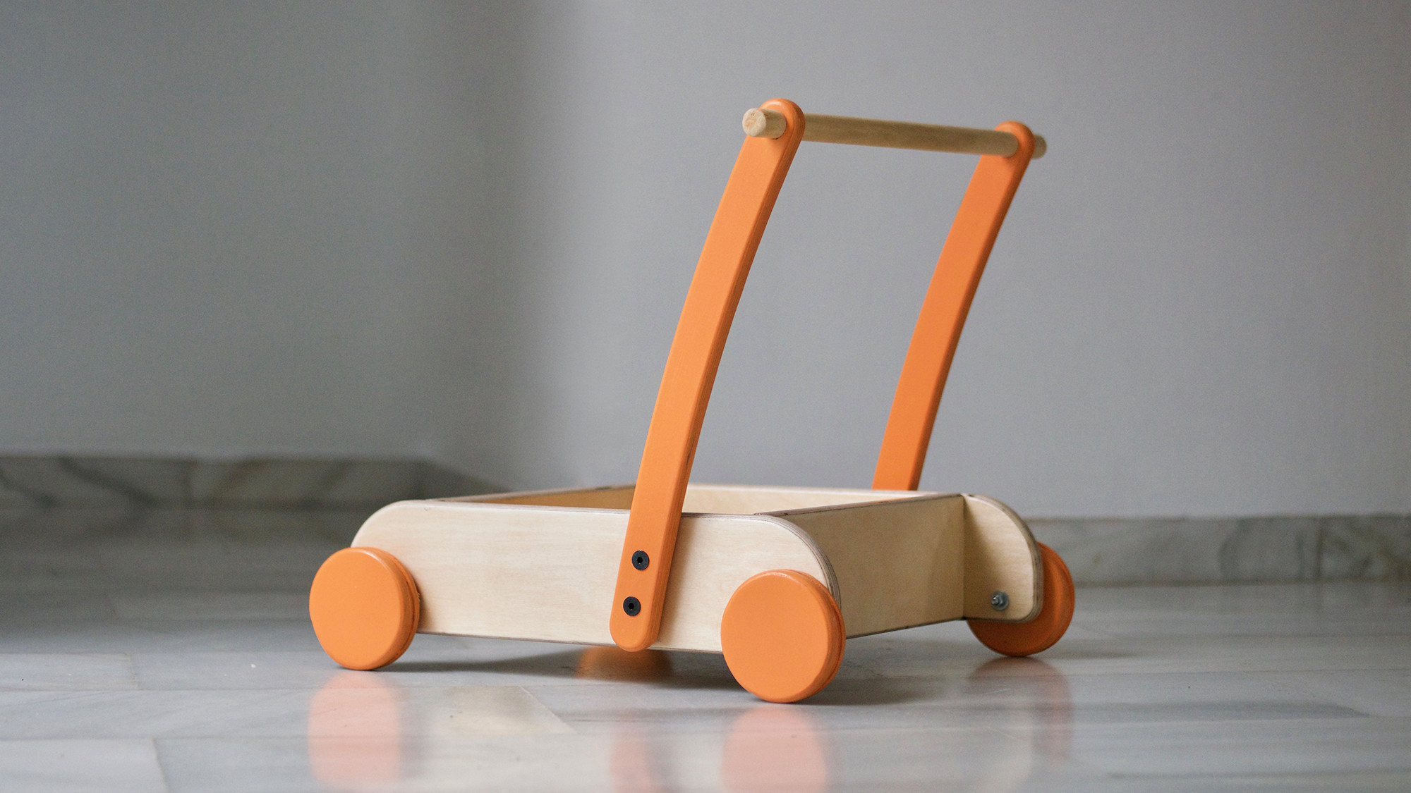
Update: Here is the baby walker painted and varnished. I used nice wax and water based paint and varnish perfect for baby toys.
Fabwindow
This week apart from the baby walker I also did work on my final project: The Fab Window, more information after the jump.