Fabacademy 2017
Second Week
Second lesson
Design tools
This week we went through a broad range of different design tool. I was particularly interested about the function (f-rep) representation paradigm vs boundary (b-rep) representation which I would identify with the design tools that I have used before. It feels clear to me that current design tools are far from ideal when design, prototyping and fabricating processes become more and more connected.
During the next weeks, I will try to learn more parametric based modelling tools such as Solidworks, Inventor and Freecad as they feel more suited for the course and my project.
As an architect, I've using Building Information Modelling tools such as Revit, Archicad and Allplan which are based on "objects" with a set of defined parameters. Within those packages there are ways of building your own "objects" although they doesn't feel as flexible as Solidworks, Inventor or Freecad.
Second assigment
Final project modelling. Window design
Most of the digital fabrication building methods for architecture that I'm aware of are focused on complete systems rather than using a "building block" approach so I'm interested in exploring this route for my final project.
The starting idea is to develop a window design which will have to meet the following main goals:
- Timber structure.
- Fabricating as many elements using fab lab technologies.
- Design should be up to current Eurocode standards on thermal insulation, waterproofing, structural integrity, fire resistance and safety.
- Design should include some input output devices such us temperature, air quality and light sensors, mechanical actuators, motorized solar control and so on.
Router and power tool manufacturer Trend-uk.com shows the process of building a timber window.
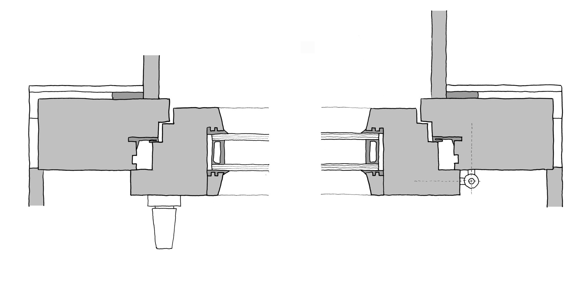
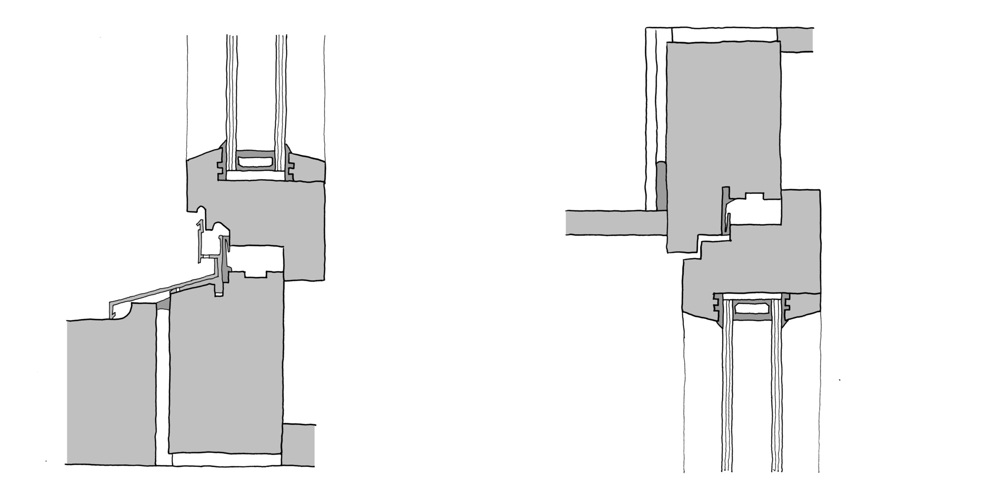
Despite a window can appear at first as a simple building component, they are generally quite sophisticated engineering and design elements which requires a substantial number of tools and multiple fabrication steps. So in order to make sure that the design would have a high performance I started analysing their shapes at a 1:1 scale.
I used swiss and german construction manuals a my primary reference material, specifically Constructing Architecture by Andrea Deplazes and Building Openings Construction Manual by Jan Cremers. Both countries have extremely high standards for timber window construction so it would be a great starting point for the project.
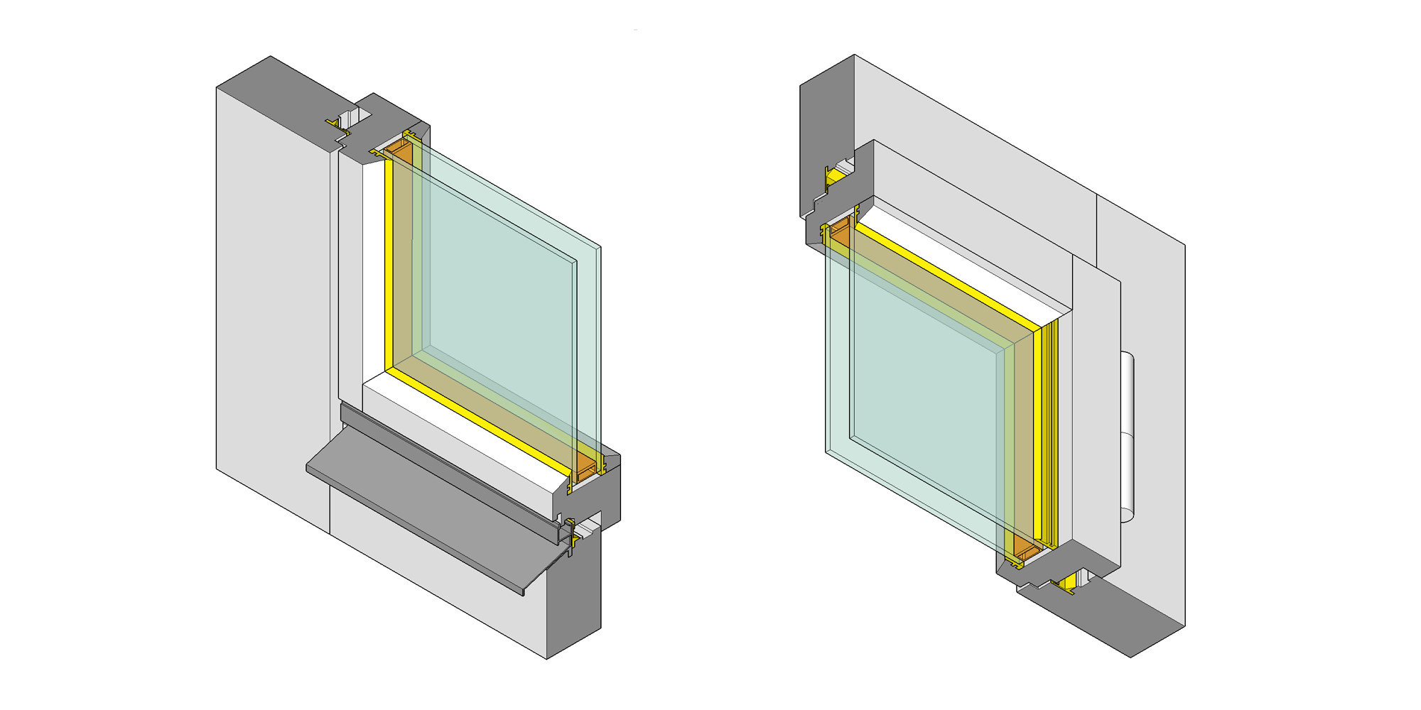
I sketched timber windows details both horizontal and vertical sections, making sure that all the different design features were properly identified. It has been a quite fascinating process to understand the reasoning behind these profiles.
Identified window elements:
- Outer frame. The outer frame is part of the window; it is fixed to the opening rebate in the reveal.
- Sash frame. The sash frame is rebated and carries the glazing. Various styles of opening are possible.
- Reveal. The reveal is the vertical side of the structural opening to which the jamb of the outer frame is fixed; its depth is equal to the thickness of the wall.
- Weatherstripping in frame rebate.Fitted to all sides of the window, the weatherstripping ensures a windproof fit preventing ingress of noise.
- Erection tape. A compressible sealing strip seals the jamb against the outer part of the reveal.
- Setting block. Setting blocks help to align the glazing temporarily before it is fixed in position.
- Glazing bead,The glazing bead is part of the sash frame and fixes the glazing in position. It is removable.
- Rubber gasket.The gasket creates a windproof seal and fixes the glazing in the frame
- Insulating glazing. two panes of glass bonded together on all sides via a spacer hermetic edge seal
- Hardware.Hardware is the overall term for the components required to assemble operate or secure the window
- Lintel a loadbearing component, is the horizontal termination of the structural opening.
- Rebates. Stepped interface between outer frame and sash frames, with peripheral weatherstripping.
- Rainwater drainage channel This channel is included to collect any water in the outer rebates of the window frame and drain it to the outside.
- Weatherstripping in frame rebate Fitted to all sides of the window, the weatherstripping ensures a windproof fit preventing ingress of noise.
- Weather bar The weather bar is required only along the bottom edge of the window; it drains the driving rain from the front of the window and from the frame rebates at the sides. It must be sealed against the sill member and the reveals (compound or gasket).
- Window sill The window sill forms the horizontal termination at the bottom of the opening. It is given a gentle fall so that water can drain to the outside. Special care is needed at the ends of the window sill. It must be ensured that water on the window sill cannot seep sideways into the reveals.
Rhinoceros
From this 1:1 (real scale) sketch models, I started to measure and draw them into horizontal and vertical vector views which would be used to build the 3D geometry. Rhinoceros is excellent for drawing fast and precise as it uses nurbs (non-uniform rational B-spline) in its geometry engine.
SketchUp
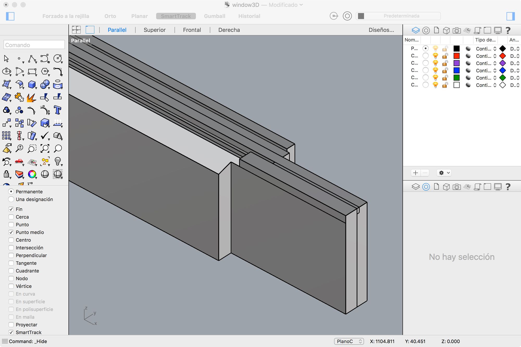
While I was modeling in Rhino, I realize that the finger joints were much more sophisticated than I first assumed and while Rhino is great for precision, Sketchup is really fast and interactive for pushing and pulling the geometry so I drew it in SketchUp to figure out the specific finger joint pattern. At this point I started to think on the final project fabrication process too.
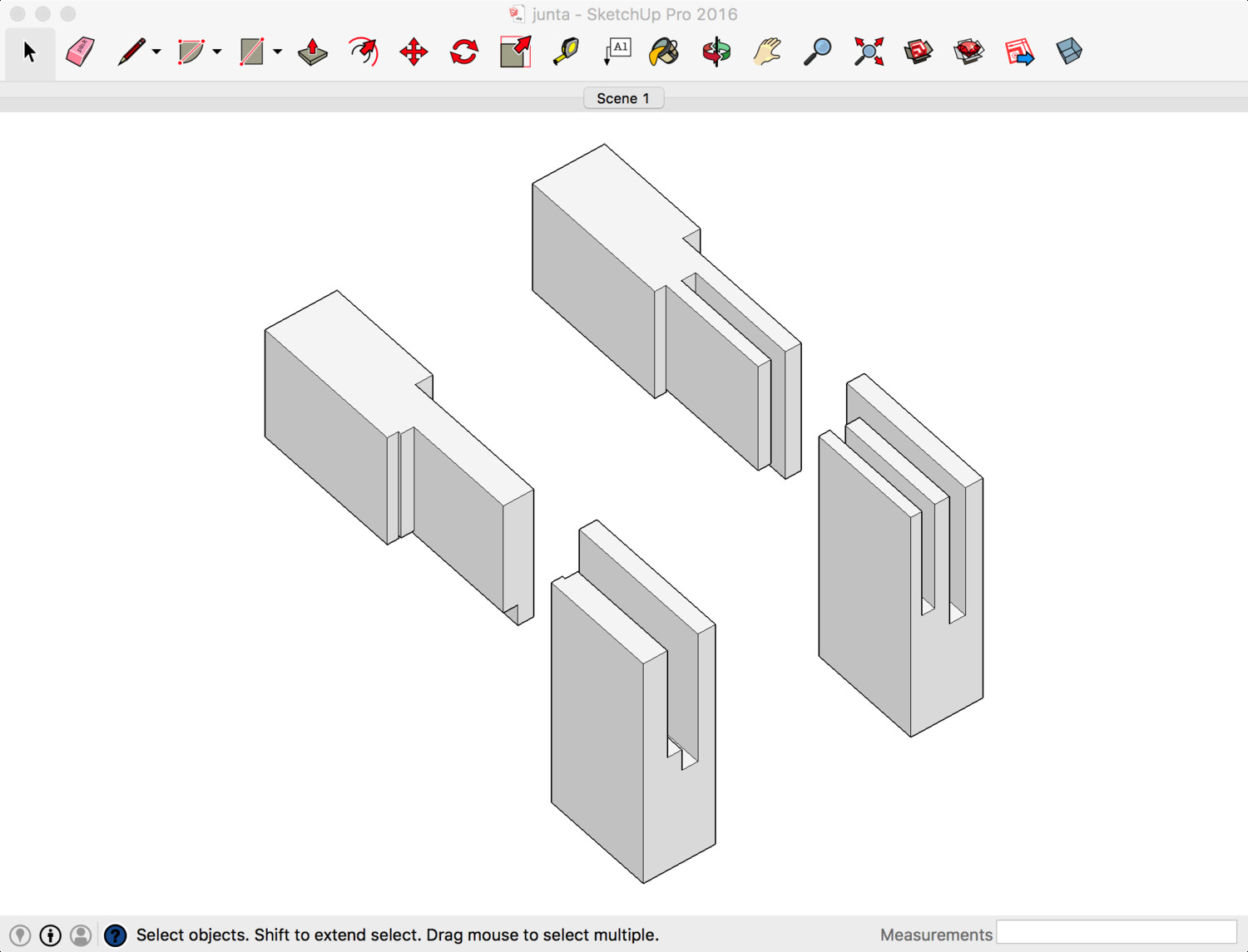
I tested three and one finger joints and based on the thickness of the frame a single finger joint seems much more adequate, I will need to test this joint on a physical prototype before validate it completely.
Complete Model
Went back to Rhino and "carved" the joints using bolean operations. I wasnt entirely happy with the way Rhino represents polysurface objects and I couldn't find a simple way to display coplanar surfaces as a single surface. Back again to SketchUp! SketchUp display settings are quite flexible so it is super fast to represent the geometry using isometric projection and setting different thicknesses for the outlines and edge lines.
I drew all the different elements and grouped them coherently using the Outliner panel, set up a couple of isometric views and exported as a raster png. Finger joints are much more complicated that I anticipated it is going to be a an interesting challenge to make a design that performs well and it is simple to fabricate and assembly.
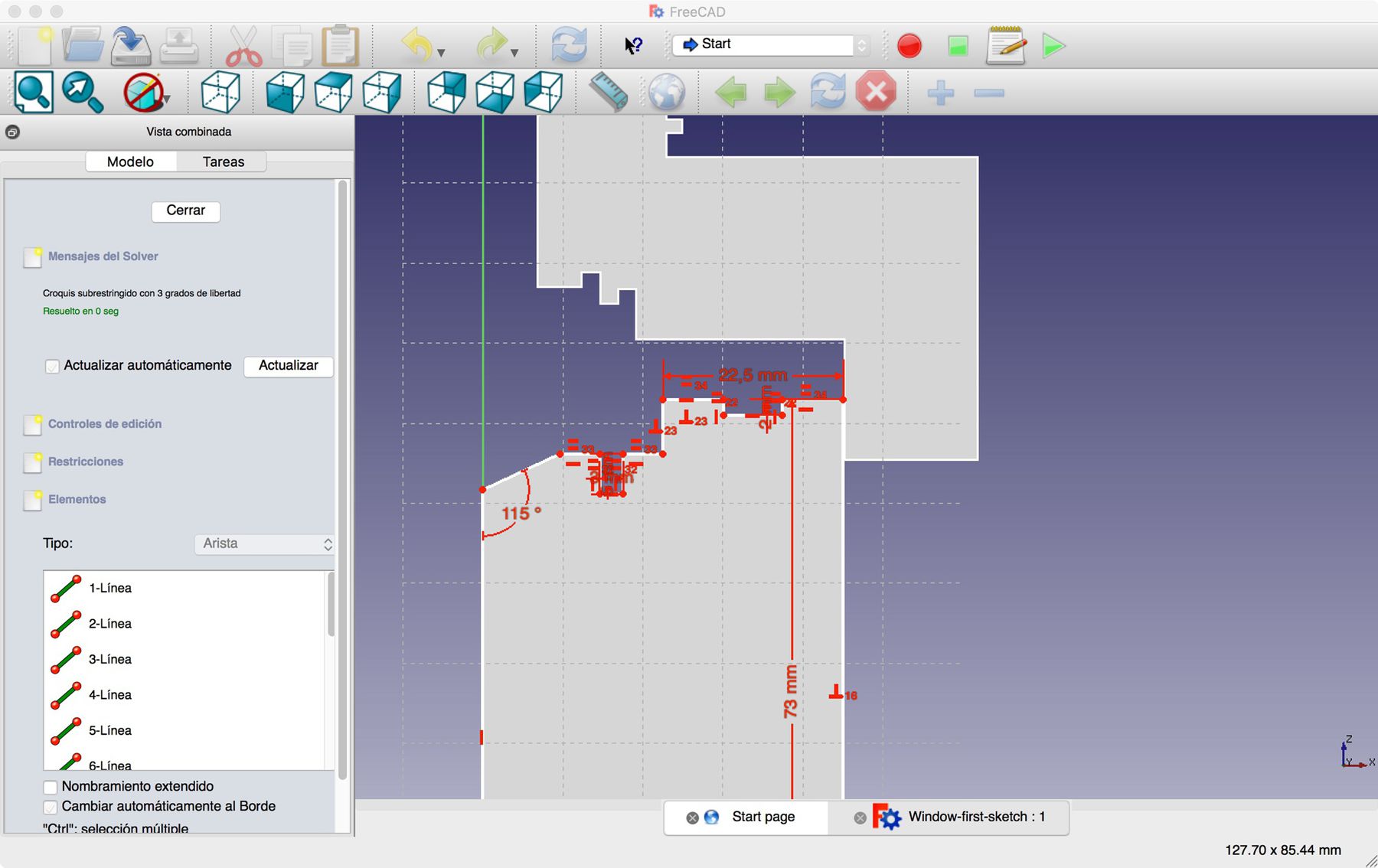
Parametric modelling
Finally, once I had a much clearer understanding of the dimensions, relationships and tridimensional shapes, I started building a parametric model in Freecad that will allow me to iterate the design faster once I start prototyping. Never used Freecad before, it feels quite powerful but the modelling process seems to be quite structured so I think it has been quite useful to model and analyze things first with SketchUp and Rhino.