Assignments:
- Read a microcontroller data sheet.
- Program your board to do something, with as many different programming languages and programming environments as possible.
- Extra credit: experiment with other architectures.
--- WORKFLOW ---
0. Change the configuration of the board in arduino for our hello echo 44 and check that it can be programmed1. Read the datasheet of the microcontroller and make a summary
2. Do tutorial exercises in arduino and understand basic references
3. Change some parameters of those exercises and observe the changes
4. Make a schematic project, for the hello echo board that does something related to my final project.
5. Make the basic program
6. Make other changes
--- 0. Change the configuration of the board in arduino for our hello echo 44 and check that it can be programmed ---
We will work with arduino and libraries of C, to configure the board you have to choose the type of microcontroller, the resonator used, as well as the programmer in this case is the FabISP.

The program its Arduino 1.8.1 Portable version.
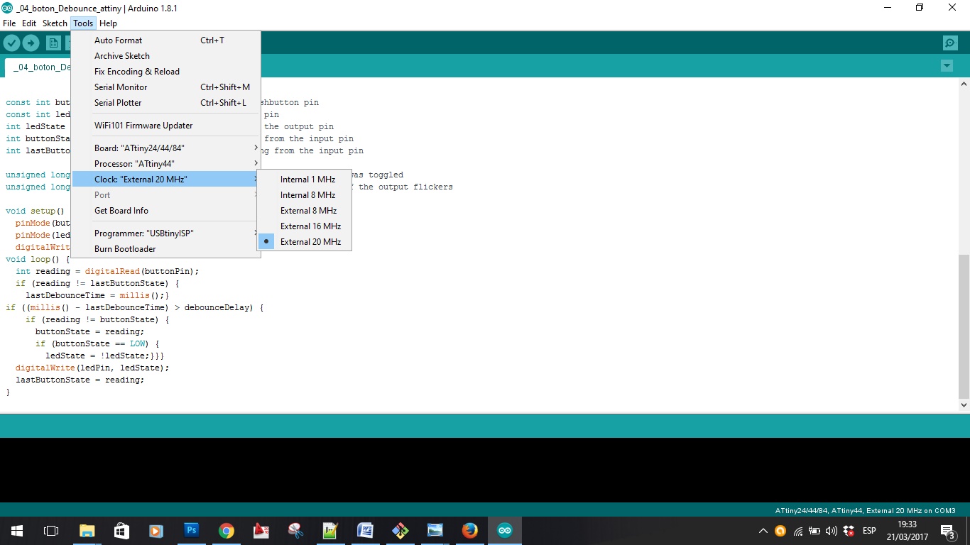
Choosing the attiny44 components
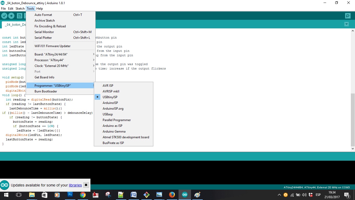
Choosing the Programmer FabISP
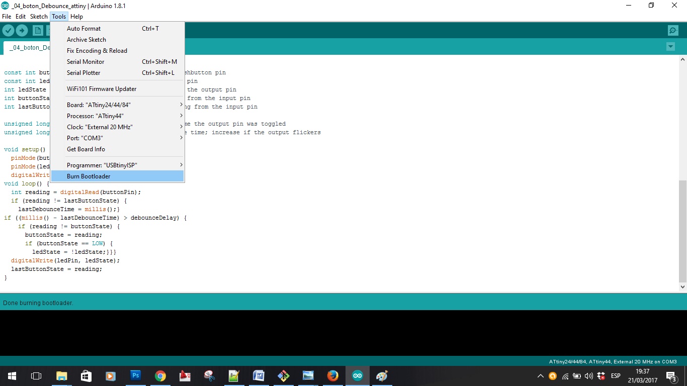
Making the bootloader
--- 1. Read the datasheet of the microcontroller and make a summary ---
I downloaded the datasheet from the atmel website.
I have studied certain parts of the datasheet, which I found to be more important.
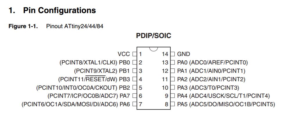 The pins and functions, very useful for the design of the boards.
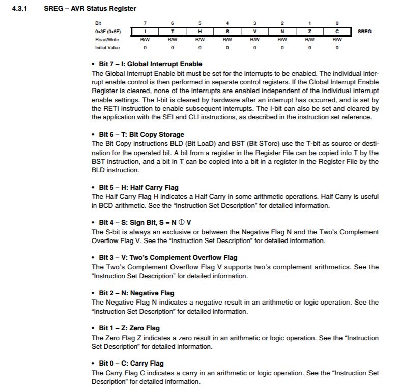 Whenever we want to modify the behavior of the microcontroller we will have to define it by programming..
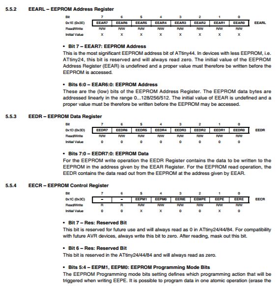
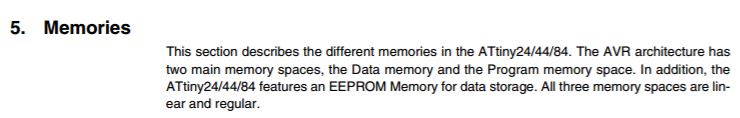 There are three types of memory, flash sram and eeprom.
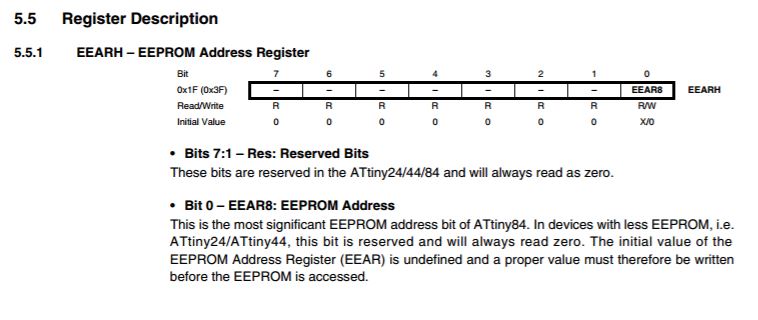 Reserved bits for memory.
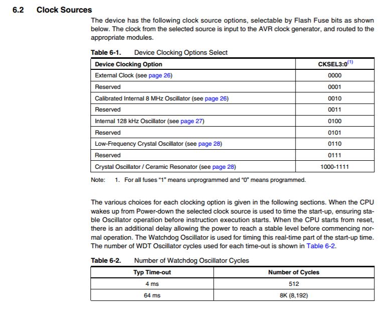 You can choose the clock source, with the programation, In arduino all this is automatic, choosing the external clock, if you want to program from c for example you have to make these configurations.
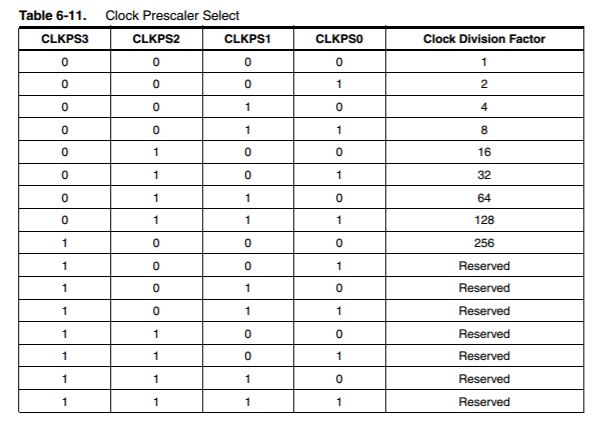
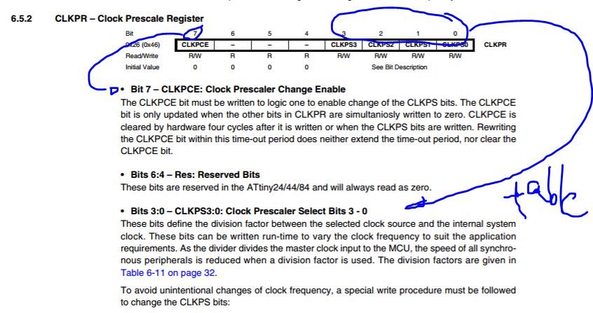 You can choose the preescaler of your clock.
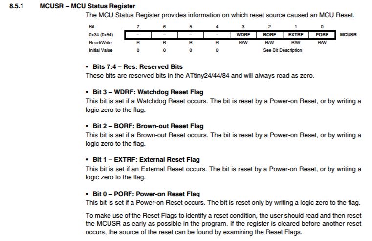 MCUSR.
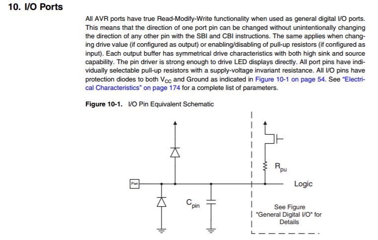 Digital pins.
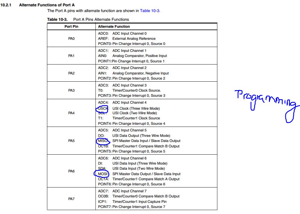 Pins of A port.
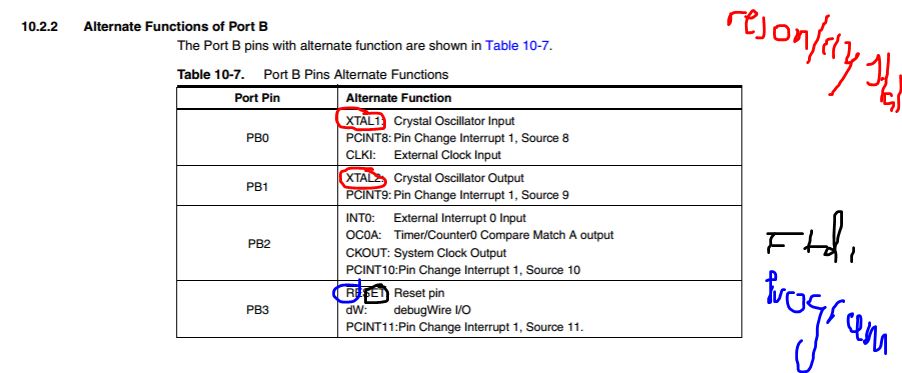 Pins of b ports.
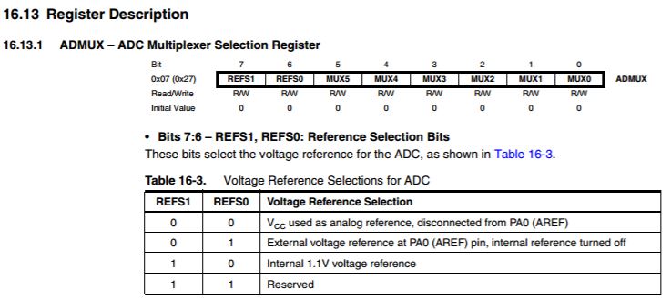 You can activate or desactivate pins with admux register.
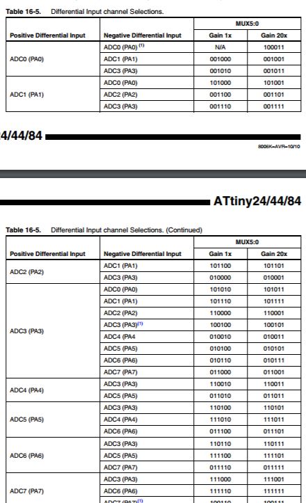 Admux clasification of the pins.
links to other programming pages where you use the datasheet for something:
LINK TO OUTPUT DEVICE WEEK 10 - I Used the Datasheet to know pins in the new Atmega 168, and for programming to know the number of the new pins, and new functions for example Pins that you can connect to Servomotor-
-LINK TO INPUT DEVICE WEEK 13 - for programming to know the number of the new pins, and new functions for example Pins that you can use to make a capacitive sensor.
--- 2,3. Do tutorial exercises in arduino and understand basic references, and change some parameters ---
I have done a series of 7 basic exercises for this device, which use various functions such as turning on a led, operating the switch, communicating in series with the computer ... etc.
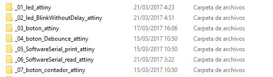
The Folders of 7 exercise tutorials.
-- Exercise 01: --
- What it does?:
Turns on an LED on for one second, then off for one second, repeatedly.
- New features:
- pinMode: Configures the specified pin to behave either as an input or an output. Syntax pinMode(pin, mode) mode: INPUT, OUTPUT, or INPUT_PULLUP.
- Constants: Constants are predefined expressions in the Arduino language. They are used to make the programs easier to read. We classify constants in groups:Boolean Constants, HIGH and LOW, INPUT, INPUT_PULLUP, and OUTPUT.
- digitalWrite: Write a HIGH or a LOW value to a digital pin. If the pin has been configured as an OUTPUT with pinMode(), its voltage will be set to the corresponding value: 5V (or 3.3V on 3.3V boards) for HIGH, 0V (ground) for LOW. Syntax- digitalWrite(pin, value)
- delay: Pauses the program for the amount of time (in miliseconds) specified as parameter. (There are 1000 milliseconds in a second.),Syntax delay(ms)
CODE:
/*
  Blink
  Turns on an LED on for one second, then off for one second, repeatedly.

  Most Arduinos have an on-board LED you can control. On the UNO, MEGA and ZERO
  it is attached to digital pin 13, on MKR1000 on pin 6. LED_BUILTIN is set to
  the correct LED pin independent of which board is used.
  If you want to know what pin the on-board LED is connected to on your Arduino model, check
  the Technical Specs of your board  at https://www.arduino.cc/en/Main/Products

  This example code is in the public domain.

  modified 8 May 2014
  by Scott Fitzgerald

  modified 2 Sep 2016
  by Arturo Guadalupi

  modified 8 Sep 2016
  by Colby Newman

  modified 15 march 2017
 by Alvaro Fernandez
*/


// the setup function runs once when you press reset or power the board
void setup() {

  // https://www.arduino.cc/en/Reference/PinMode
  // https://www.arduino.cc/en/Reference/Constants
  // initialize digital pin LED_BUILTIN as an output.
  pinMode(13, OUTPUT);
   pinMode(A2, OUTPUT);
}

// the loop function runs over and over again forever
void loop() {

  // https://www.arduino.cc/en/Reference/DigitalWrite
  // https://www.arduino.cc/en/Reference/Delay

  digitalWrite(A3, HIGH);   // turn the LED on (HIGH is the voltage level)
  delay(500);
   digitalWrite(A3, LOW);   // turn the LED on (HIGH is the voltage level)
delay(500);
}
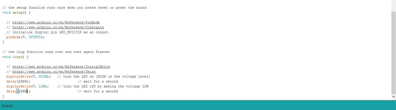
The 01 exercise tutorial.
Doing changes in the blink speed.
-- Exercise 02: --
- What it does?:
Turns on and off a light emitting diode (LED) connected to a digital pin, without using the delay() function. This means that other code can run at the same time without being interrupted by the LED code.
- New features:
- Int: Integers are your primary data-type for number storage. On the Arduino Uno (and other ATMega based boards) an int stores a 16-bit (2-byte) value. This yields a range of -32,768 to 32,767 (minimum value of -2^15 and a maximum value of (2^15) - 1).
- Assignment: Stores the value to the right of the equal sign in the variable to the left of the equal sign.
- Variables: A variable is a place to store a piece of data. It has a name, a value, and a type. For example, this statement (called a declaration),The advantage of a variable in this case is that you only need to specify the actual number of the pin once, but you can use it lots of times.
- UnsignedLong: Unsigned long variables are extended size variables for number storage, and store 32 bits (4 bytes). Unlike standard longs unsigned longs won't store negative numbers, making their range from 0 to 4,294,967,295 (2^32 - 1).
- If: if, which is used in conjunction with a comparison operator, tests whether a certain condition has been reached, such as an input being above a certain number.
- Else: If/else allows greater control over the flow of code than the basic if statement, by allowing multiple tests to be grouped together. For example, an analog input could be tested and one action taken if the input was less than 500, and another action taken if the input was 500 or greater.
- Millis: Returns the number of milliseconds since the Arduino board began running the current program. This number will overflow (go back to zero), after approximately 50 days.
CODE:
/* Blink without Delay
Turns on and off a light emitting diode (LED) connected to a digital
pin, without using the delay() function. This means that other code
can run at the same time without being interrupted by the LED code.
The circuit:
* Use the onboard LED.
* Note: Most Arduinos have an on-board LED you can control. On the UNO, MEGA and ZERO
it is attached to digital pin 13, on MKR1000 on pin 6. LED_BUILTIN is set to
the correct LED pin independent of which board is used.
If you want to know what pin the on-board LED is connected to on your Arduino model, check
the Technical Specs of your board at https://www.arduino.cc/en/Main/Products
created 2005
by David A. Mellis
modified 8 Feb 2010
by Paul Stoffregen
modified 11 Nov 2013
by Scott Fitzgerald
modified 9 Jan 2017
by Arturo Guadalupi
modified 15 march 2017
by Alvaro Fernandez
This example code is in the public domain.
*/
// http://www.arduino.cc/en/Tutorial/BlinkWithoutDelay
// https://www.arduino.cc/en/Reference/Int
// https://www.arduino.cc/en/Reference/Const
// https://www.arduino.cc/en/Reference/Assignment
// https://www.arduino.cc/en/Tutorial/Variables
// https://www.arduino.cc/en/Reference/VariableDeclaration
/*Constant define una variable y al llevar int después define que es una variable de tipo de datos int da un valor entre 32767 y -32768 */
const int ledPin = 7;// the number of the LED pin
int ledState = LOW; // ledState used to set the LED
unsigned long previousMillis = 0; // will store last time LED was updated
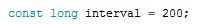
const long interval = 200; // interval at which to blink (milliseconds)
void setup() {
pinMode(ledPin, OUTPUT);
}
void loop() {
unsigned long currentMillis = millis();
if (currentMillis - previousMillis >= interval) {
previousMillis = currentMillis;
if (ledState == LOW) {
ledState = HIGH;
} else {
ledState = LOW;
}
digitalWrite(ledPin, ledState);
}
}
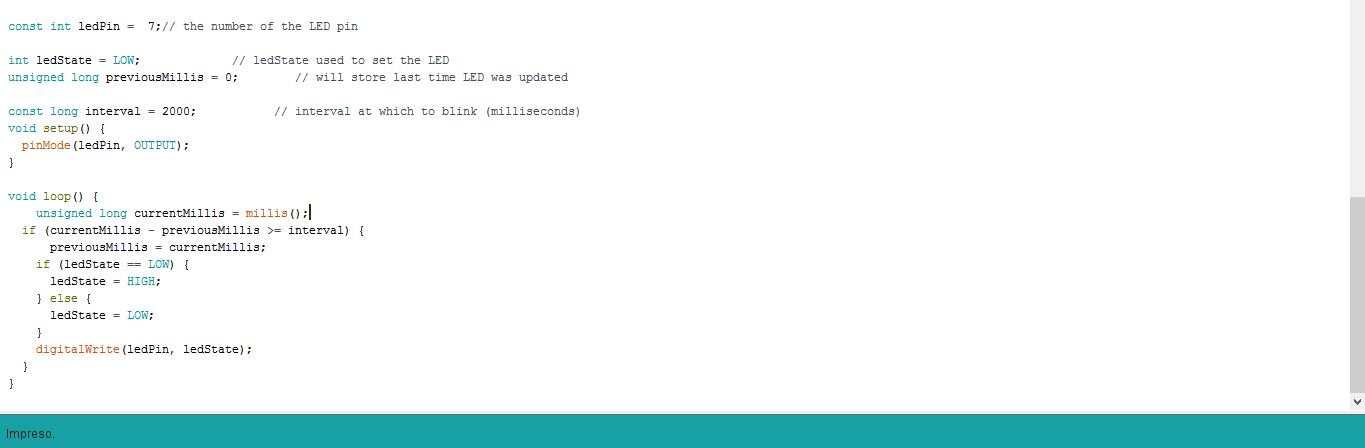
Exercise 03
Making the interval faster. to 300millis in low mode and high mode
-- Exercise 03: --
- What it does?:
Turns on and off a light emitting diode (LED) connected to a digital
pin, without using the delay() function. This means that other code
can run at the same time without being interrupted by the LED code.
- New features:
- InputPullupSerial: This example demonstrates the use of INPUT_PULLUP with pinMode(). It monitors the state of a switch by establishing serial communication between your Arduino and your computer over USB. Additionally, when the input is HIGH, the onboard LED attached to pin 13 will turn on; when LOW, the LED will turn off.
- DigitalRead: Reads the value from a specified digital pin, either HIGH or LOW.
CODE:
modified 15 march 2017
 by Alvaro Fernandez


const int buttonPin = 8;     // the number of the pushbutton pin
const int ledPin =  7;      // the number of the LED pin
int buttonState = 0;         // variable for reading the pushbutton status
void setup() {
  pinMode(ledPin, OUTPUT);

  pinMode(buttonPin, INPUT);
}

void loop() {
  buttonState = digitalRead(buttonPin);
  if (buttonState == LOW) {
    digitalWrite(ledPin, LOW);
  } else {
    digitalWrite(ledPin, HIGH);
  }
}
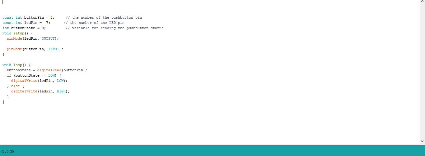
Exercise03 code, using the switch without noise cleaning
-- Exercise 04: --
- What it does?:
Each time the input pin goes from LOW to HIGH (e.g. because of a push-button press), the output pin is toggled from LOW to HIGH or HIGH to LOW. There's a minimum delay between toggles to debounce the circuit (i.e. to ignore noise).
- New features:
- DebounceDelay: the debounce time; increase if the output flickers. Joined to lastDebounceTime: the last time the output pin was toggled for this reference - lastDebounceTime) > debounceDelay)
CODE:
/*
 Debounce

 Each time the input pin goes from LOW to HIGH (e.g. because of a push-button
 press), the output pin is toggled from LOW to HIGH or HIGH to LOW.  There's
 a minimum delay between toggles to debounce the circuit (i.e. to ignore
 noise).

 The circuit:
 * LED attached from pin 13 to ground
 * pushbutton attached from pin 2 to +5V
 * 10K resistor attached from pin 2 to ground

 * Note: On most Arduino boards, there is already an LED on the board
 connected to pin 13, so you don't need any extra components for this example.


 created 21 November 2006
 by David A. Mellis
 modified 30 Aug 2011
 by Limor Fried
 modified 28 Dec 2012
 by Mike Walters
 modified 30 Aug 2016
 by Arturo Guadalupi
 modified 15 march 2017
 by Alvaro Fernandez


 This example code is in the public domain.

 http://www.arduino.cc/en/Tutorial/Debounce
 */


const int buttonPin = 8;    // the number of the pushbutton pin
const int ledPin = 7;      // the number of the LED pin
int ledState = LOW;         // the current state of the output pin
int buttonState;             // the current reading from the input pin
int lastButtonState = HIGH;   // the previous reading from the input pin

unsigned long lastDebounceTime = 0;  // the last time the output pin was toggled
unsigned long debounceDelay = 50;    // the debounce time; increase if the output flickers

void setup() {
  pinMode(buttonPin, INPUT_PULLUP);
  pinMode(ledPin, OUTPUT);
  digitalWrite(ledPin, ledState);}
void loop() {
  int reading = digitalRead(buttonPin);
  if (reading != lastButtonState) {
    lastDebounceTime = millis();}
if ((millis() - lastDebounceTime) > debounceDelay) {
    if (reading != buttonState) {
      buttonState = reading;
      if (buttonState == LOW) {
        ledState = !ledState;}}}
  digitalWrite(ledPin, ledState);
  lastButtonState = reading;
}
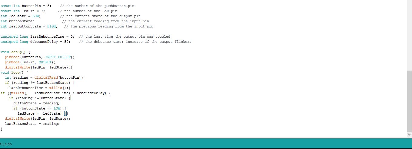
Using the button like an interruptor.
-- Exercise 05: --
Each time the input pin goes from LOW to HIGH (e.g. because of a push-button press), the output pin is toggled from LOW to HIGH or HIGH to LOW. There's a minimum delay between toggles to debounce the circuit (i.e. to ignore noise).
- New features:
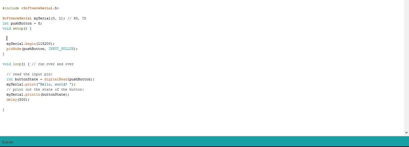
- Include: include is used to include outside libraries in your sketch. This gives the programmer access to a large group of standard C libraries (groups of pre-made functions), and also libraries written especially for Arduino.
- Serial: Serial is used for communication between the Arduino board and a computer or other devices. All Arduino boards have at least one serial port (also known as a UART or USART): Serial. It communicates on digital pins 0 (RX) and 1 (TX) as well as with the computer via USB. Thus, if you use these functions, you cannot also use pins 0 and 1 for digital input or output.
- Begin: Sets the data rate in bits per second (baud) for serial data transmission. For communicating with the computer, use one of these rates: 300, 600, 1200, 2400, 4800, 9600, 14400, 19200, 28800, 38400, 57600, or 115200. You can, however, specify other rates - for example, to communicate over pins 0 and 1 with a component that requires a particular baud rate.
- Println: Prints data to the serial port as human-readable ASCII text followed by a carriage return character (ASCII 13, or '\r') and a newline character (ASCII 10, or '\n'). This command takes the same forms as Serial.print().
CODE:
#include <SoftwareSerial.h>

SoftwareSerial mySerial(0, 1);
const int  buttonPin = 8;   // elegir el pin 8 como botón
const int ledPin = 7;      // elegir el pin 7 de led
int buttonPushCounter = 0;   // contador de botón
int buttonState = 0;         //
int lastButtonState = 0;     //
void setup() {
  // put your setup code here, to run once:
   pinMode(buttonPin, INPUT_PULLUP); // elegir el botón como input pullup
   pinMode(ledPin, OUTPUT); // elegir el led como salida
   mySerial.begin(115200); // terminal, y elegir la velocidad del puerto
}
void loop() {
  // put your main code here, to run repeatedly:
  buttonState = digitalRead(buttonPin); // enlaza el stado del botón con la lectura del pin del botón
if (buttonState != lastButtonState) { //
     if (buttonState == LOW) {
      buttonPushCounter++;
if (buttonPushCounter % 3 -1 == 0)
  mySerial.println("system re-established");
  if (buttonPushCounter % 3 -2 == 0)
  mySerial.println("Warning,vehicle is approaching!");
if (buttonPushCounter % 3 == 0)
      mySerial.println("Evacuation");
       }
    delay(50);
  }
  lastButtonState = buttonState;
  if (buttonPushCounter % 3 == 0) { //el contador de pulsaciones del botón, divisor de 3 entonces el pin se pone high para cualquier otro low
     digitalWrite(ledPin, HIGH);
  } else {
     digitalWrite(ledPin, LOW);
  }
}
Exercise 05 serial answer
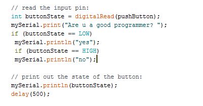
My mod, changing the parameters and introducing if.
-- Exercise 06: --
- What it does?:
The LED of the device will be ON when the desired code is entered from the arduino terminal, the same will happen to turn off, in this case 5+enter to turn On and 8+enter to turn Off
- New features:
- Else/if: if/else allows greater control over the flow of code than the basic if statement, by allowing multiple tests to be grouped together. For example, an analog input could be tested and one action taken if the input was less than 500, and another action taken if the input was 500 or greater. The code would look like this:
#include <SoftwareSerial.h>
SoftwareSerial mySerial(0, 1); // RX, TX
const int ledPin = 7; // the pin that the LED is attached to
void setup() {
mySerial.begin(115200);
pinMode(ledPin, OUTPUT);}
void loop() {
byte encendido;
if (mySerial.available()) {
encendido = mySerial.read();
if (encendido == '5') {
digitalWrite(ledPin, HIGH);
mySerial.println("On");}
else if (encendido == '8'){
digitalWrite(ledPin, LOW);
mySerial.println("Off");
}
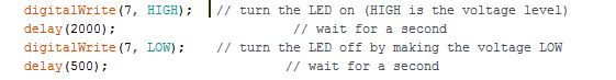
else if (encendido == '3'){
digitalWrite(7, HIGH); // turn the LED on (HIGH is the voltage level)
delay(500); // wait for a second
digitalWrite(7, LOW); // turn the LED off by making the voltage LOW
delay(500);
digitalWrite(7, HIGH); // turn the LED on (HIGH is the voltage level)
delay(500); // wait for a second
digitalWrite(7, LOW); // turn the LED off by making the voltage LOW
delay(500);
mySerial.println("Blink");
}
else{
mySerial.println("5 encender y 8 apagar.");
}
}
}
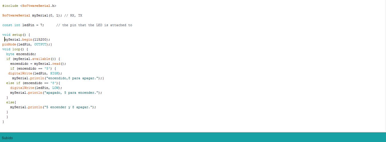
a serial comunication, 5+enter to turn On and 8+enter to turn Off
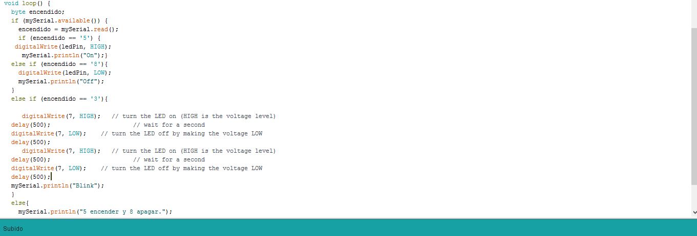
More complicated mod,5+enter to turn On and 8+enter to turn Off 3+enter blinks two times, and print the names of the voids.
-- Exercise 07: --
- What it does?:
This time only the led will be activated if the number of times pressed is divisible by 4.
The other times it will be off, also in serial will output the number of times the button has been pressed
- New features:
- %: Calculates the remainder when one integer is divided by another. It is useful for keeping a variable within a particular range. Syntax result = dividend % divisor
- buttonPushCounter++: Increases the value by one unit of the variable int ButtonPushCounter, ++ is an operator that means plus of 1 unit.
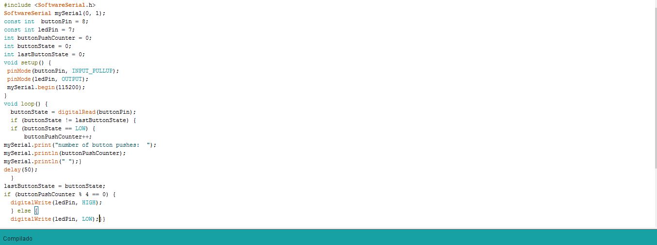
Exercise 07 code.
#include <SoftwareSerial.h>

SoftwareSerial mySerial(0, 1);

const int  buttonPin = 8;
const int ledPin = 7;

int buttonPushCounter = 0;
int buttonState = 0;
int lastButtonState = 0;

void setup() {

  pinMode(buttonPin, INPUT_PULLUP);

  pinMode(ledPin, OUTPUT);

  mySerial.begin(115200);
}


void loop() {

  buttonState = digitalRead(buttonPin);


  if (buttonState != lastButtonState) {

    if (buttonState == LOW) {
      buttonPushCounter++;

      mySerial.print("number of button pushes:  ");
      mySerial.println(buttonPushCounter);
      mySerial.println(" ");
    }

    delay(50);
  }

  lastButtonState = buttonState;

  if (buttonPushCounter % 4 == 0) {
     digitalWrite(ledPin, HIGH);
  } else {
     digitalWrite(ledPin, LOW);
  }

}
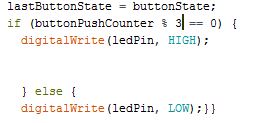
Changing the number of pulsations at three.
--- 4. Make a schematic project, for the hello echo board that does something related to my final project. ---
I want to make a program that is similar to my final project, with the limitations of the microcontroller attiny.
We will simulate that the button is the pressure sensor of my final project, and that it is activated when I pulse it.
The first time the pulse sends a warning that a vehicle is approaching, the second time activates the alarms, the led and warns you in series that you have to evacuate the square.
To restart the alarm and lower the barriers, press the button again.
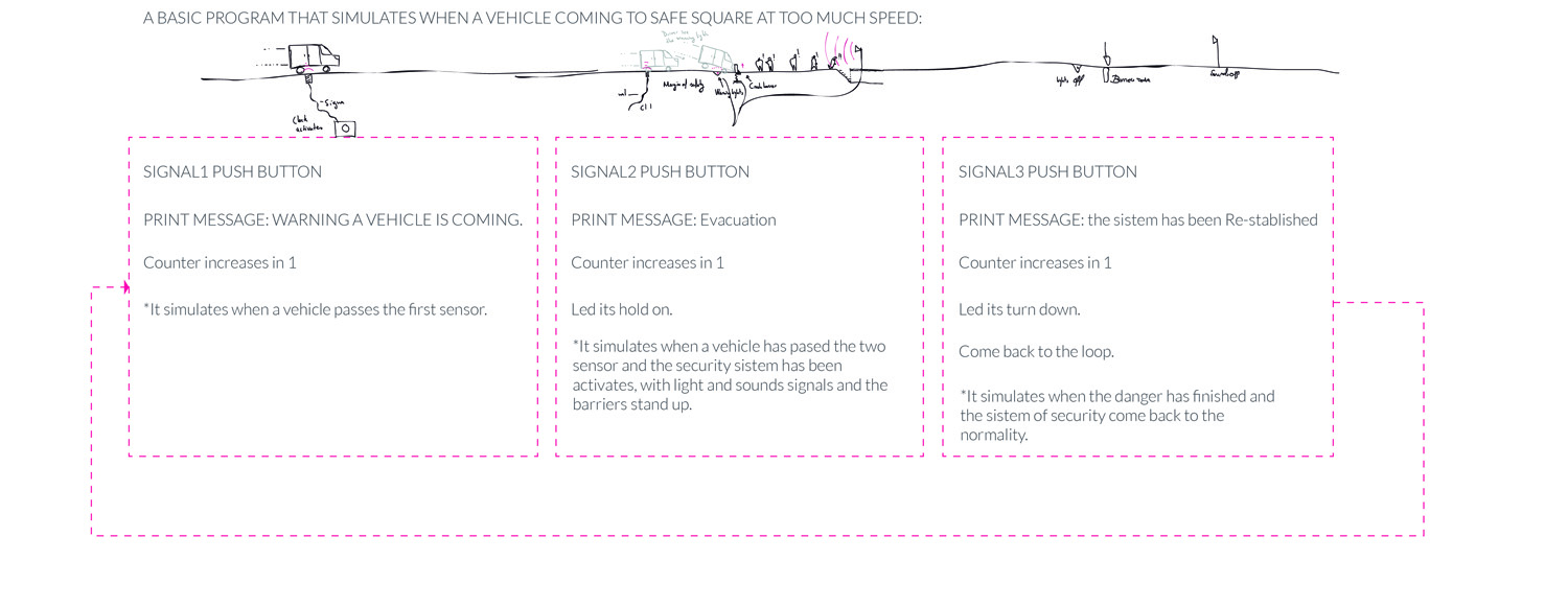
a schematic program.
--- 5. Make the basic program ---
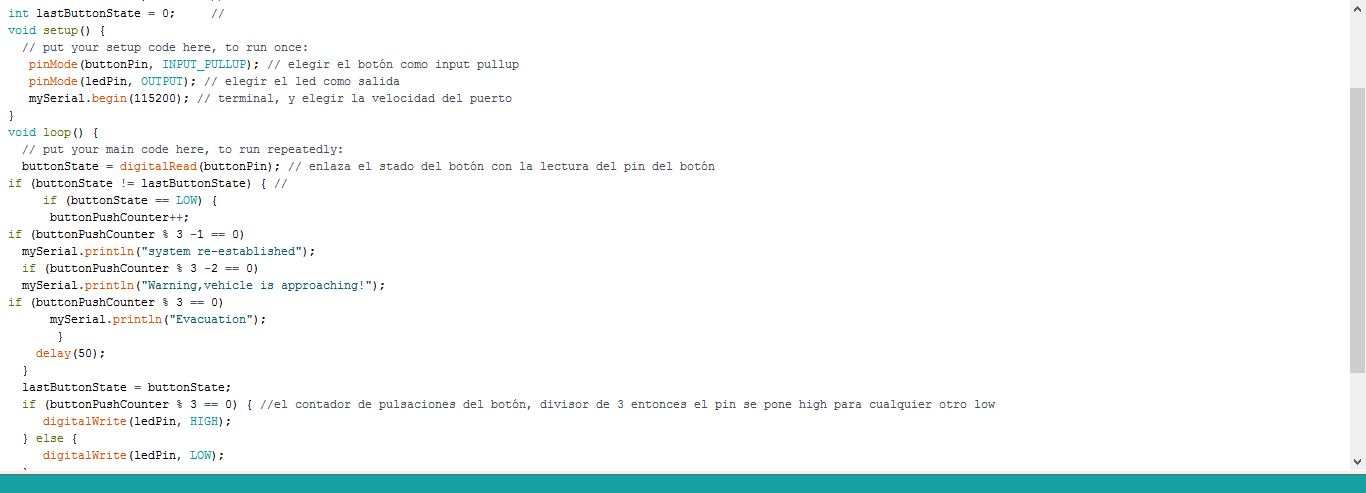
The program is similar to Exercise 7 but a bit more complex, introducing the different println by each of the button presses.
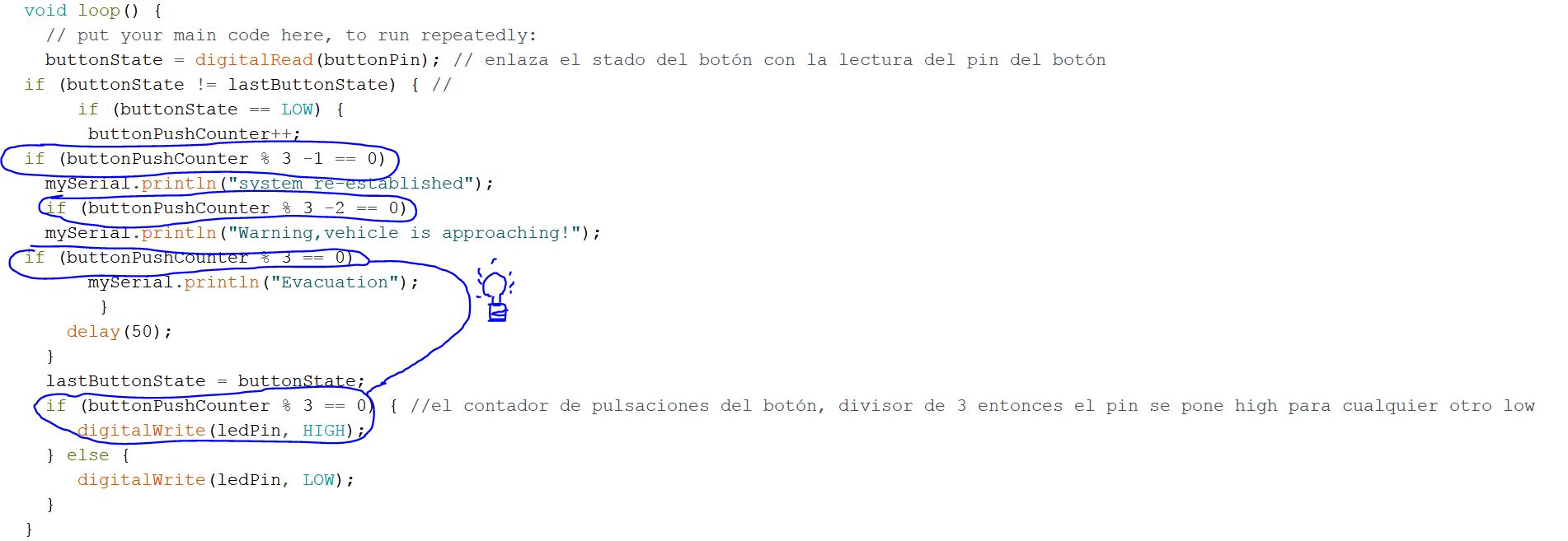
New functions for each the button presses.
#include <SoftwareSerial.h>

SoftwareSerial mySerial(0, 1);
const int  buttonPin = 8;   // elegir el pin 8 como botón
const int ledPin = 7;      // elegir el pin 7 de led
int buttonPushCounter = 0;   // contador de botón
int buttonState = 0;         //
int lastButtonState = 0;     //
void setup() {
  // put your setup code here, to run once:
   pinMode(buttonPin, INPUT_PULLUP); // elegir el botón como input pullup
   pinMode(ledPin, OUTPUT); // elegir el led como salida
   mySerial.begin(115200); // terminal, y elegir la velocidad del puerto
}
void loop() {
  // put your main code here, to run repeatedly:
  buttonState = digitalRead(buttonPin); // enlaza el stado del botón con la lectura del pin del botón
if (buttonState != lastButtonState) { //
     if (buttonState == LOW) {
      buttonPushCounter++;
if (buttonPushCounter % 3 -1 == 0)
  mySerial.println("system re-established");
  if (buttonPushCounter % 3 -2 == 0)
  mySerial.println("Warning,vehicle is approaching!");
if (buttonPushCounter % 3 == 0)
      mySerial.println("Evacuation");
       }
    delay(50);
  }
  lastButtonState = buttonState;
  if (buttonPushCounter % 3 == 0) { //el contador de pulsaciones del botón, divisor de 3 entonces el pin se pone high para cualquier otro low
     digitalWrite(ledPin, HIGH);
  } else {
     digitalWrite(ledPin, LOW);
  }
}
My program
Conclusions:
Learning to program is like learning a new language with the difference that you have to be precise because microcontrollers do not interpret.
The attiny is the most basic of microcontrollers, and for some actions programmed with arduino its memory is insufficient.
What questions do you have? What would you like to learn more about?
I would like to know more about the parts of the microcontroller and different options, such as to change the speed and the correct use of some pins, I have to investigate more about it.
I would also like to know how to optimize memory when programming, since with Atiny I am short of memory for any more complex program.
I would like to know to program in C to see in more depth all the options of the microcontroller, to choose the pins accessing the registers, and giving orders of form more complex than with arduino and the function PinMode.