Assignments:
- add an output device to a microcontroller board you've designed and program it to do something.
--- WORKFLOW ---
For fabricate my board and my output I have followed this workflow.0. Think about the output we want to perform 1. Make the scheme of the board that we need for our output
2. Designing in Eagle the circuit
3. Export the design and mill the plate.
4. Solder all components.
5. Check that it works.
6. Programming to do something.
0. Think about the output we want to perform:
For my final project, I would need a motor that made a movement and with that movement activated a spring.
The motor it could be a servomotor.
He has the property to move to a certain position.
1. Perform the schematic of the board that we need for our output and circuit.
We need:
4 capacitors (2 x 0.1,1,10,22uf)
2 resistors (499, 10k)
1 led
1 atmel microcontroller atmega168P
1 IC REG LDO 3.3V 1A SOT223-3
1 8mhz resonator
1 ftdi connection
1 6x1 pin header
2 2x2 pin header (battery charger, serial)
1 3Pin header
1 Switch 6mm 1 LED RED CLEAR 1206 SMD- This is a first circuit diagram:
2. Design the circuit in Eagle:
2.1 Read the Datasheet to add an output:
PWM signals are commonly used for speed control of DC motors (if you decrease the duty cycle on the control signal of the power circuit that acts on the motor the motor moves slowly), adjust the brightness intensity of a LED, etc.
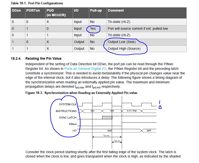
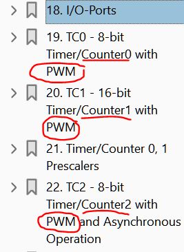
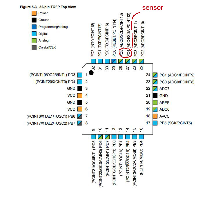
Input/Output ports
In the datasheet.
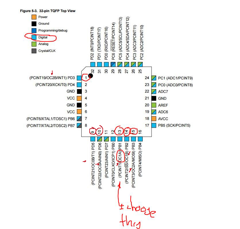
I need to put the servomotor in a PWM pin but .... Where are they?
the pins having this function in ATmega 168 and Atmega 328 are those having the OC characteristic they are PB1 PB2 (OC1 A-B) PB3 PD3 (OC2 A-B) PD5 PD6 (OC0 B-A).
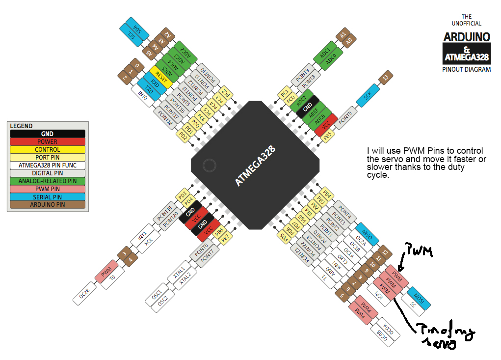
PWM pins situation
In Arduino, with ATmega168 or ATmega328, the output signal PWM (pins 3,5,6,9,10, and 11) is a frequency signal approximately 490 Hz and it only allows us to change the "duty cycle" or time that the pulse is active (on) or inactive (off), using the function analogWrite ()
Modifying the registers and the prescaler we can change the frequency of measurement of the timer and thus adjust it to the amount of high and low that we want to send to the output.
Where are the information in the datasheet?

Features of OC1 timer
So by changing the value of the value parameter in the function analogWrite (pin, value), we can get different work cycles:
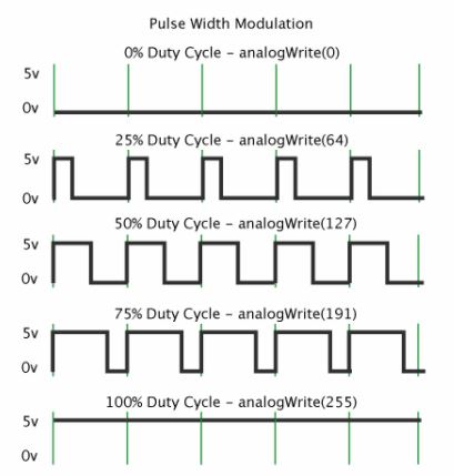
How works the PWM pin with different frequencies of analog write.
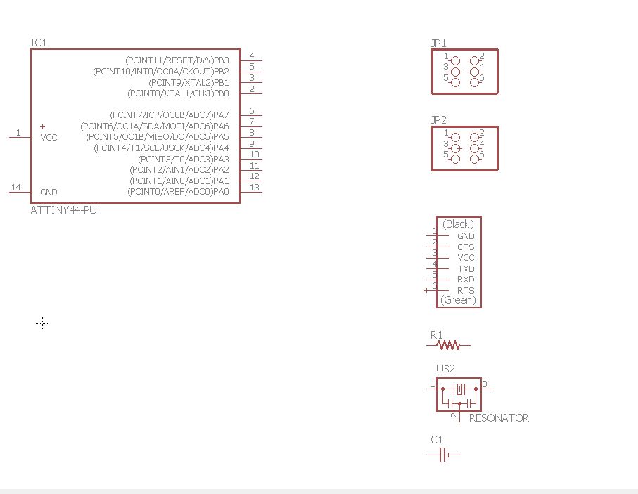
2.2 Design in eagle:
It's one of the hardest parts for me.
I started creating a new project, and with the help of Fabkit and helloservo, I understood how many components I needed and how to join them.
I started the exercise with the microcontroller atmega 328P, one quite more powerful than the atiny 44 that gave me many more options when programming.
I've been adding components and linking them together.
This was a first schematic design and the plate totally failed, since I was missing very important pieces.
placing the components.
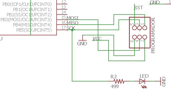
connecting the pins
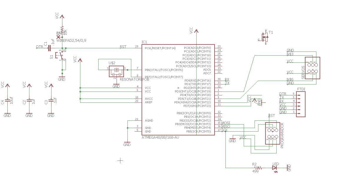
near but its wrong.
I have had many problems because I found it difficult to design the circuit, the microcontroller atmega 328p has many more pins than the attiny and it is more complicated to do the design and understand how it works.
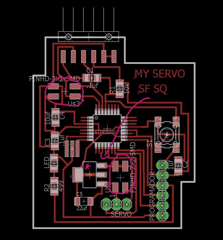
However I gotta make this board design:
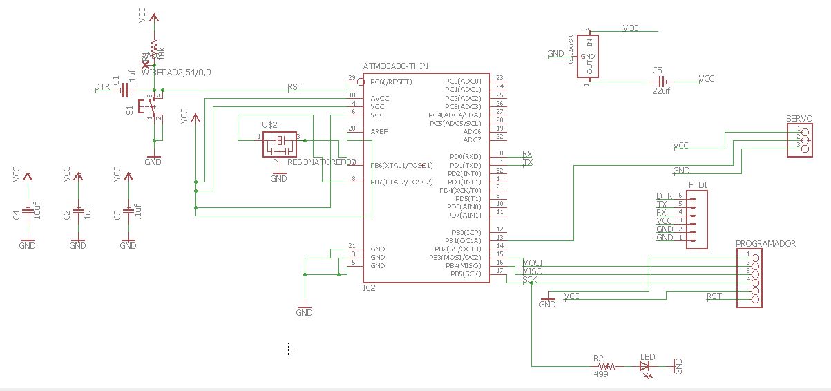
Final schematic
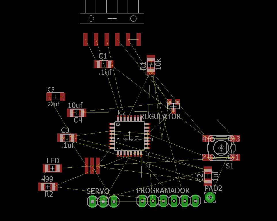
board design
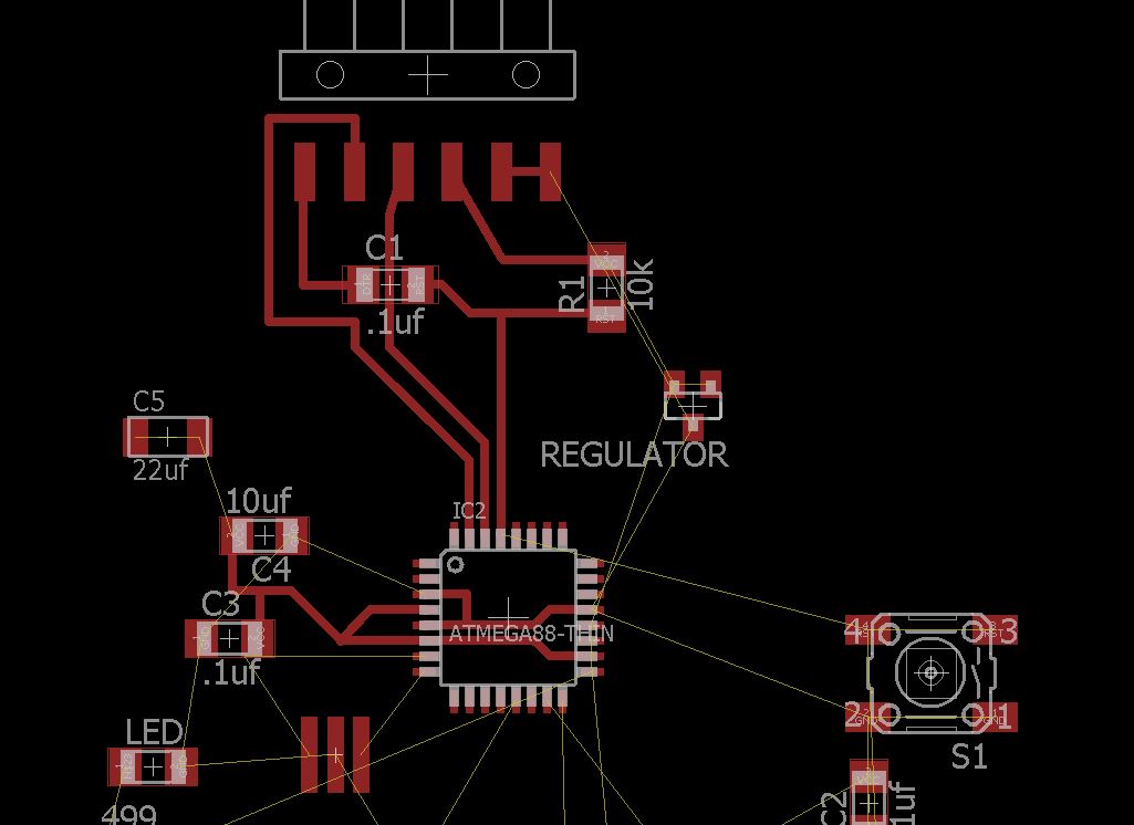
making connections
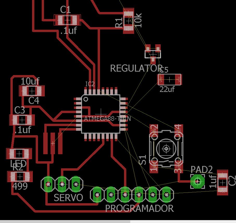
this is not easy
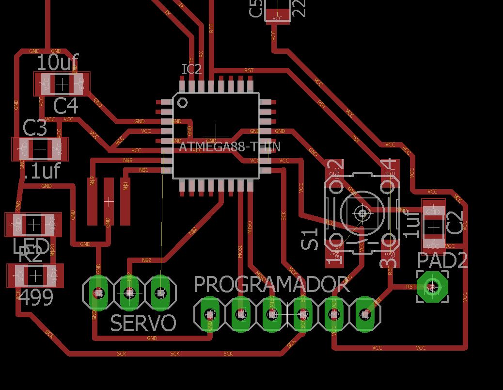
connecting the servo
The result
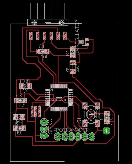
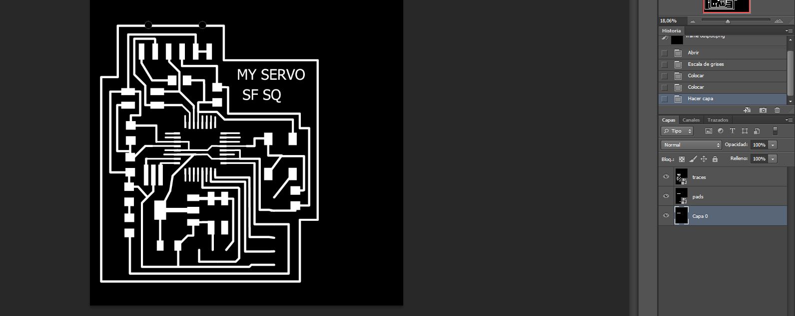
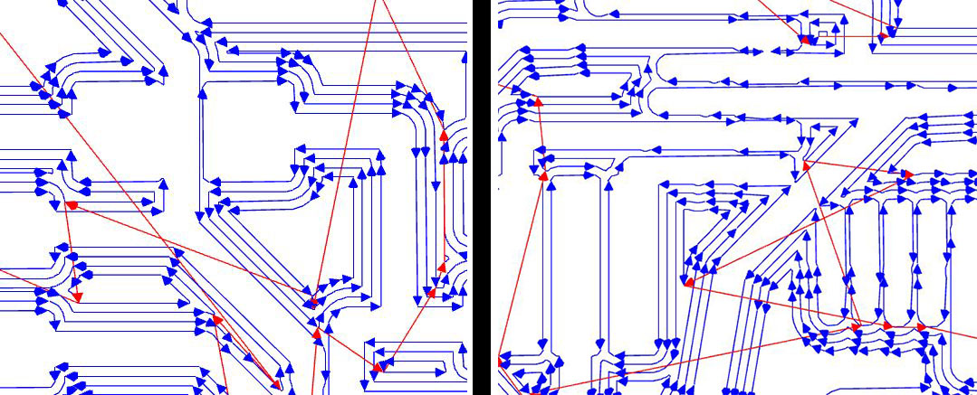
3. Export the design and mill the board:
First I exported from Eagle in monochrome mode, I set the frame in photoshop and I created several layers in photoshop with pads and frame
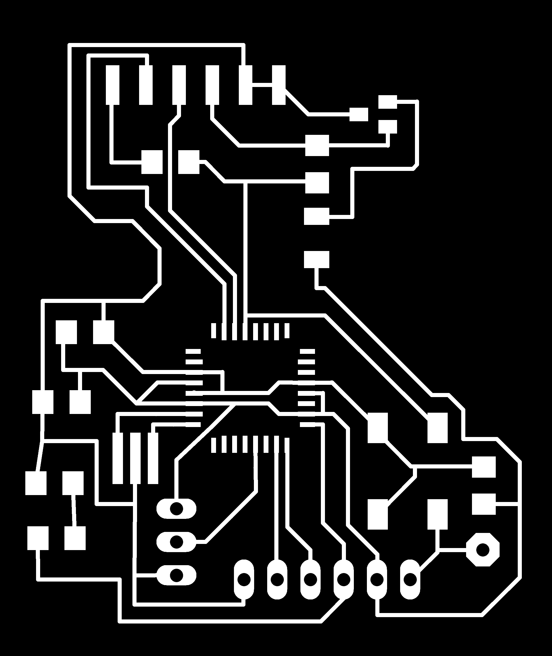
board in png, monochrome and 1300dpi

Pads, that will be milled with 1/32 milling cutter

Frame.

using mods
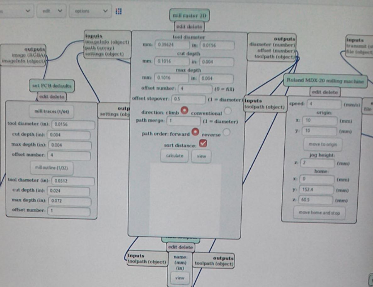
Parameters
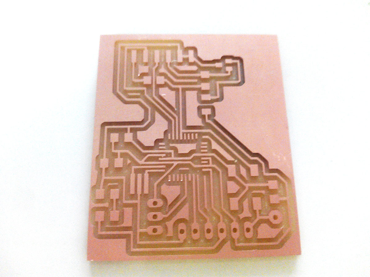
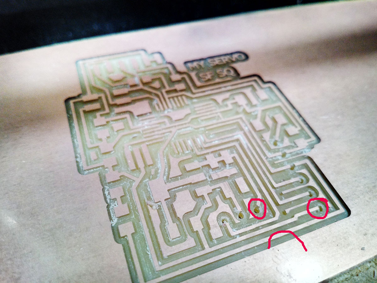
the circuit milled
PROBLEMS:
I did not take into account when designing the board leave a connection with an external power supply, in case I want to read or send data in serial while performing operations with the servomotor.
I also did not take into account that this was not the voltage regulator I needed, that added to the design of the plate was not good, I decided to re-randomize everything correctly.
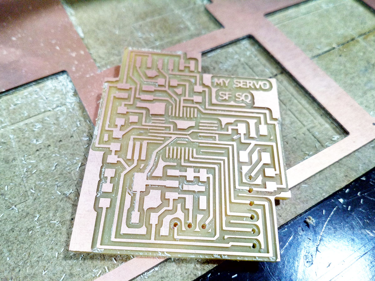
We make all the changes mentioned before, new design from blocks.
I add the feed and a pin if I want to communicate it in series with another plate.
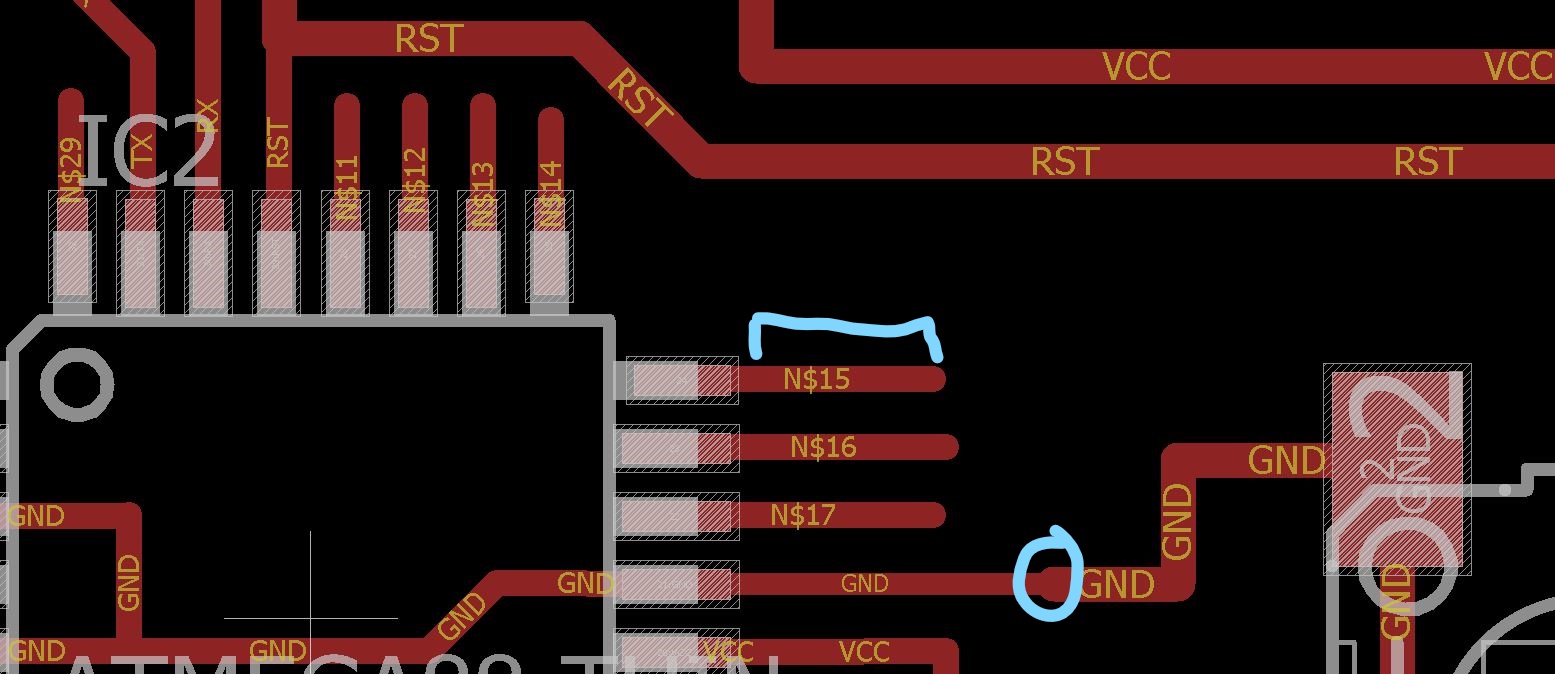
Redefined the size of the wire in some pins, and add a section in each pin to be able to solder it better.
Creating a free form for my Board, always I do rectangular boards, I Tested it.
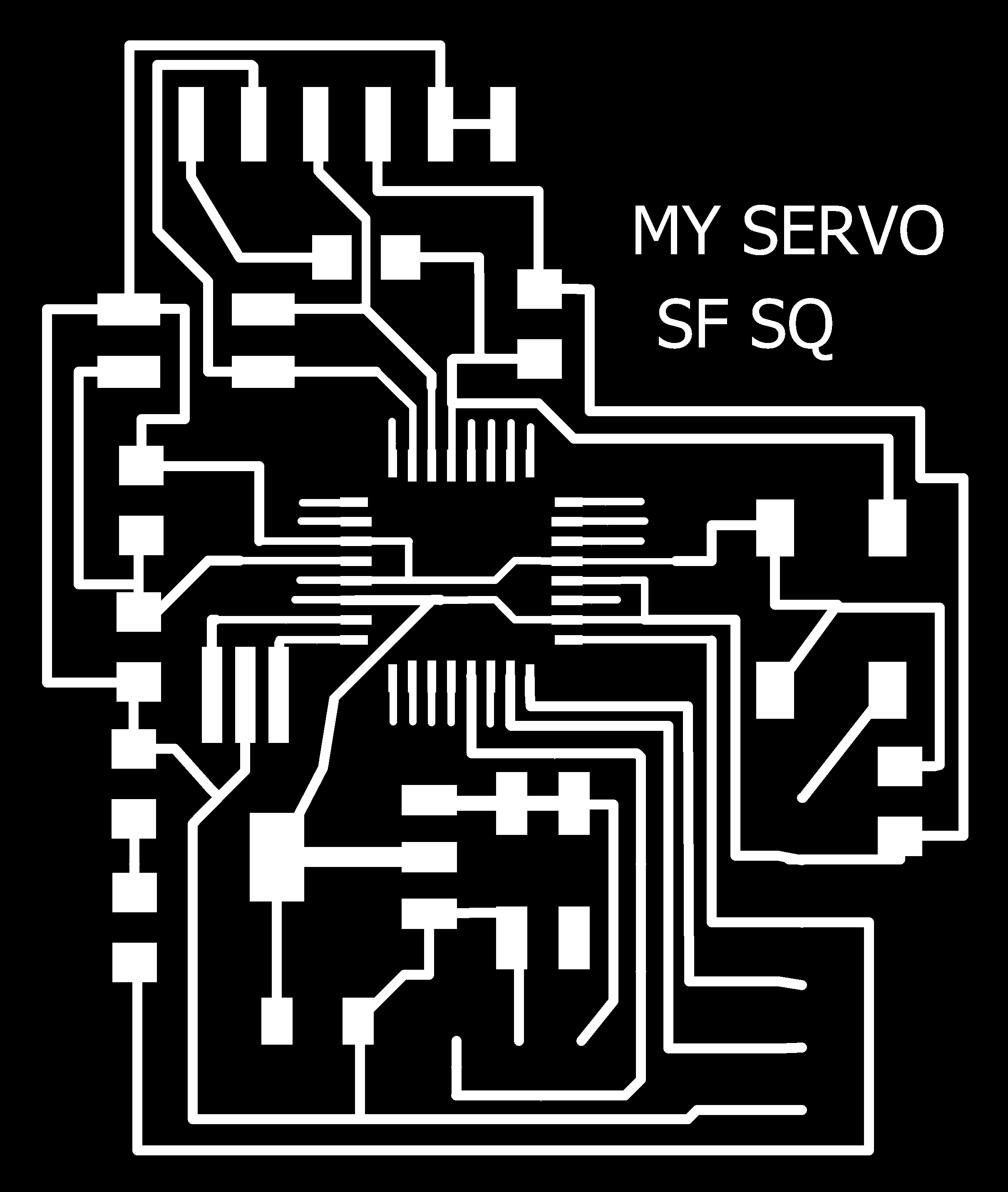
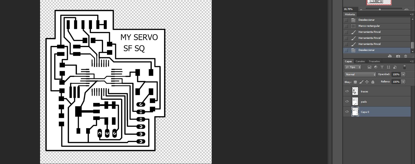
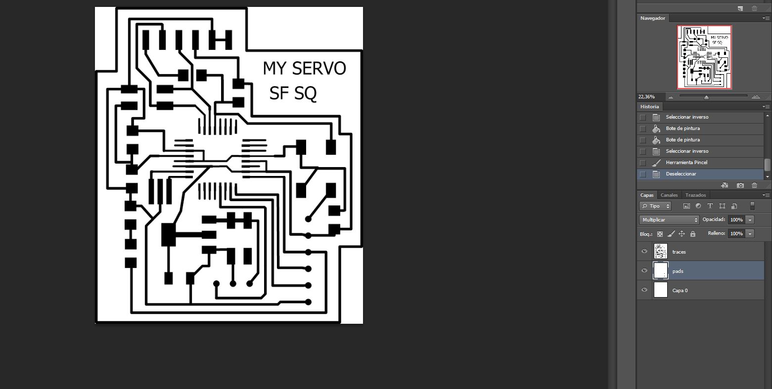
Traces, ATENTION, THIS PNG ITS THAT I USED,BUT THE PADS ARE NOT IN THE IMAGE, IT WAS A FAILURE TO PREPARE THE CUTTING FILE.

Pads

Frame
I had some errors, de diameter it was ok and I checked the design rules, but the mistakes are minimum I corrected it with Photoshop, but can also be done by redrawing the wire
4. Solder all components:
It was difficult to solder because there were many pin connections, I also had a small error making the pads, because I forgot to include the pads in the traces layer.
This was the result of solder:
Small mistake.
my board
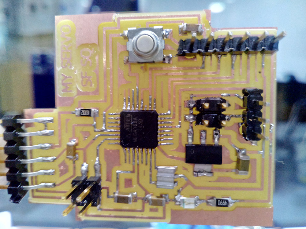
the board soldered.
5. Check that it works:
I made the checks with the multimeter, and I re-soldered some pin that was not soldered correctly. I went to arduino, connect my board with fabISP and did the bootloader. The bootloader was done correctly.
6. Programming to do something:
There are many examples, for servomotors and there is an arduino bookstore exclusive to them.
I have tried with 2 examples that come on the web of arduino, knop and sweep,
The datasheet said me that my pin is the 9.
Knop: uses a potentiometer to control the servo.
Code:
/*
 Controlling a servo position using a potentiometer (variable resistor)
 by Michal Rinott <http://people.interaction-ivrea.it/m.rinott>

 modified on 8 Nov 2013
 by Scott Fitzgerald
 http://www.arduino.cc/en/Tutorial/Knob
*/

#include <Servo.h>

Servo myservo;  // create servo object to control a servo

int potpin = 0;  // analog pin used to connect the potentiometer
int val;    // variable to read the value from the analog pin

void setup() {
  myservo.attach(9);  // attaches the servo on pin 9 to the servo object
}

void loop() {
  val = analogRead(potpin);            // reads the value of the potentiometer (value between 0 and 1023)
  val = map(val, 0, 1023, 0, 180);     // scale it to use it with the servo (value between 0 and 180)
  myservo.write(val);                  // sets the servo position according to the scaled value
  delay(15);                           // waits for the servo to get there
}
Sweep: the servomotor performs two 180 ° loop sweeps.
Code:
/* Sweep
 by BARRAGAN <http://barraganstudio.com>
 This example code is in the public domain.

 modified 8 Nov 2013
 by Scott Fitzgerald
 http://www.arduino.cc/en/Tutorial/Sweep
*/

#include <Servo.h>

Servo myservo;  // create servo object to control a servo
// twelve servo objects can be created on most boards

int pos = 0;    // variable to store the servo position
int act = 180
void setup() {
  myservo.attach(9);  // attaches the servo on pin 9 to the servo object
}

void loop() {
 // for (pos = 0; pos <= 180; pos += 1) { // goes from 0 degrees to 180 degrees
    // in steps of 1 degree
    myservo.write(pos);              // tell servo to go to position in variable 'pos'
    delay(1000);                       // waits 15ms for the servo to reach the position
  }
 // for (pos = 180; pos >= 0; pos -= 1) { // goes from 180 degrees to 0 degrees
    myservo.write(act);              // tell servo to go to position in variable 'pos'
    delay(150);                       // waits 15ms for the servo to reach the position
  }
}
My program:
A simple program to move the servomotor, between 2 positions (rest and Active) with a different delay.
Simulate the function I would have in my final project in a simplified way.
/* inspired in Sweep
 by BARRAGAN <http://barraganstudio.com>
 This example code is in the public domain.

 modified 8 Nov 2013
 by Scott Fitzgerald
 http://www.arduino.cc/en/Tutorial/Sweep

modified 25 May 2017 by alvarolaroja

*/

#include <Servo.h>

Servo myservo;  // create servo object to control a servo
// twelve servo objects can be created on most boards

int pos = 10;    // variable to store the servo position
int act = 160;
void setup() {
  myservo.attach(9);  // attaches the servo on pin 9 to the servo object
}

void loop() {
 // for (pos = 0; pos <= 180; pos += 1) { // goes from 0 degrees to 180 degrees
    // in steps of 1 degree AQUI TENDRÍA QUE PONER UN IF, EN EL CUAL SERÍA SI LEO X EN EL MONITOR SERIAL EL SERVOMOTOR SE MUEVE, A ACT TRAS 5 SEGUNDOS VUELVE A LA POS INICIAL Y SE PARA.

    myservo.write(pos);              // tell servo to go to position in variable 'pos'
    delay(4000);                       // waits 15ms for the servo to reach the position

 // for (pos = 180; pos >= 0; pos -= 1) { // goes from 180 degrees to 0 degrees
    myservo.write(act);              // tell servo to go to position in variable 'pos'
    delay(1000);                       // waits 15ms for the servo to reach the position
  }
FINAL VIDEO:
Program of my final project:
As a program made by me from 0, for the output is the one I will use for my final project, what I want is that when I receive a signal for the serial monitor of 5, a certain angle is moved and when I receive an 8 return to the initial position.
#include <SoftwareSerial.h>

#include <Servo.h>


Servo finalservo;

int pos = 10;
int act = 160;
int encendido=0;
void setup(){
Serial.begin(9600);

  myservo.attach(9);
}

void loop() {


  if (Serial.available()) {
    encendido = Serial.read();
    /*if (encendido == '5') {

        // servo en posicion pos
       myservo.write(pos);


      }
      */
      // Si es una 'L'
      if (encendido == '8'){

        myservo.write(pos);              // tell servo to go to position in variable 'pos'
                          // waits 15ms for the servo to reach the position*/

      delay(1000);
      }

            myservo.write(act);

 /*// for (pos = 0; pos <= 180; pos += 1)

    myservo.write(pos);
    delay(4000);
 // for (pos = 180; pos >= 0; pos -= 1)
    myservo.write(act);
    delay(1000);
  }
 }
FILES: you can download the latest version of the board at this link (pngs included):
fabservo
Also Arduino File:
Arduino
Also finalpf output Arduino File:
Finalservopf