
Interface and Application Programming
Introduction
In this Week the task is to make i cicuit board with an input or output. program the board and make it interface with a mobile through a BlueTooth interface.
I went though a lot of readings and testing for this week. Therefore, the best way to demonstrate my work this week i will explain each process at a time.
My Plan
I plan to use IR Module sensor and link it to the mobile through Bluetooth device in order to get readings in case the distance get interfered with an object.
MIT App Inventor
In his week, it was my first time using MIT App Inventor. I went through tutorials on youtube in order to understand the way of using the application.
Here are some links used as reference:
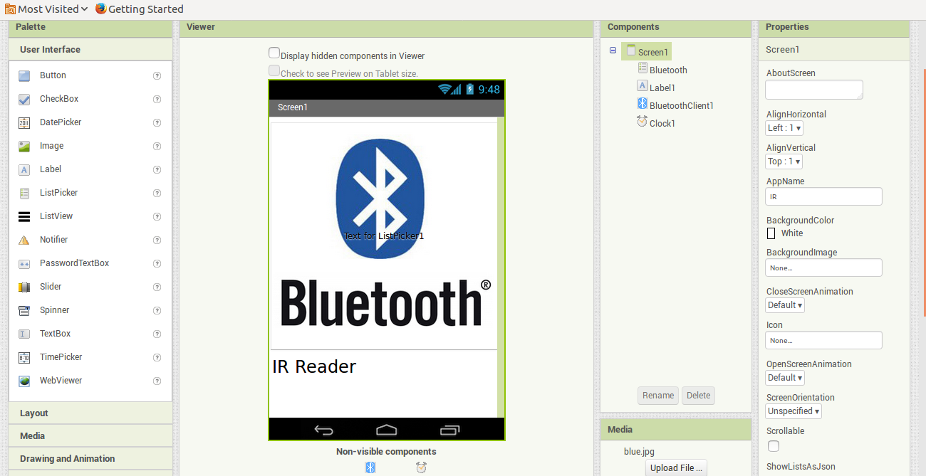
The app part need to be done on two phases, the Designer part and the Blocks part:
In the designer part i added the following:
1) List Picker from User Interface.
2) BluetoothClient from Connectivity.
3) Clock from Sensors."used for IR readings from the circuit board"
In each of the elements mentioned above I did some tuning using the Properties such as adding Picture for the bluetooth, changing the alignment, Text size ...etc.
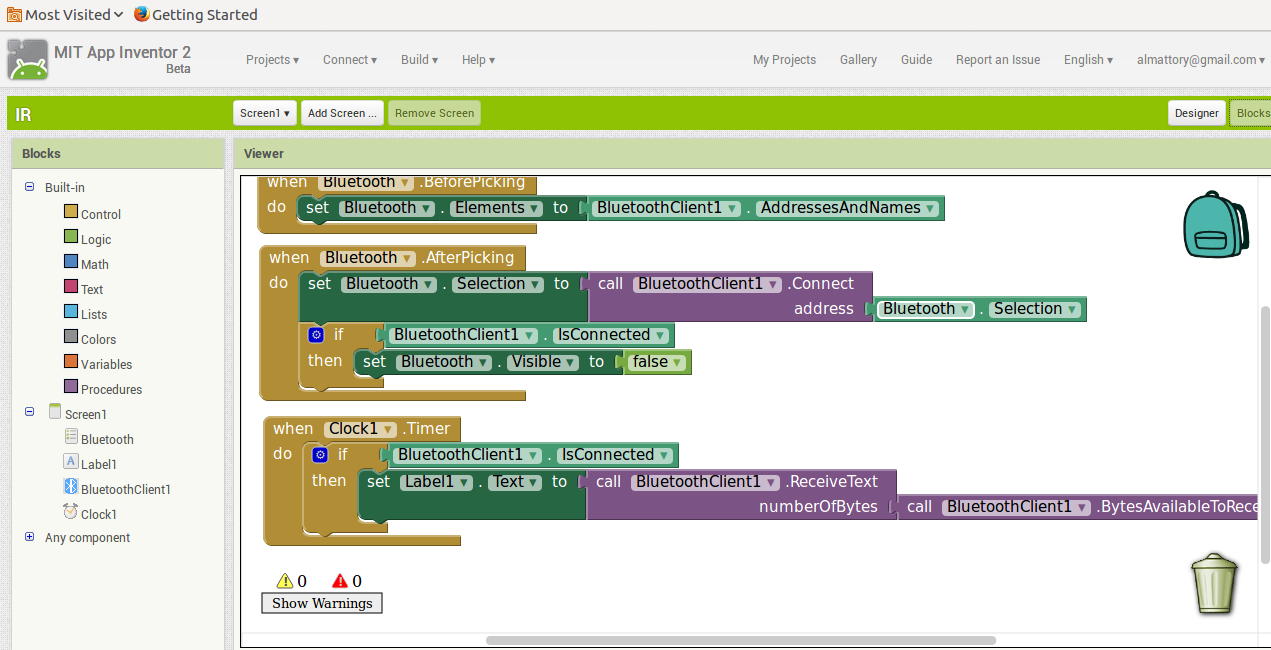
In the Blocks part I set the conditions in which my app behave based on the elements added above. and the sequense was as follow:
1) Bluetooth.Before Picking: the bluetooth view the list of available bluetooth connections.
2) Bluetooth.After Picking: after selecting a bluetooth name, establish a connection. Once connected, hide the image i used as bluetooth icon in order to show how the app behave. this step has been added in later stages as during running the app the numbers was shown on top of the icon and it was not a good presentation.
3) After establishing the connection. the app read from the bluetooth device the readings of the IR installed in my circuit board.
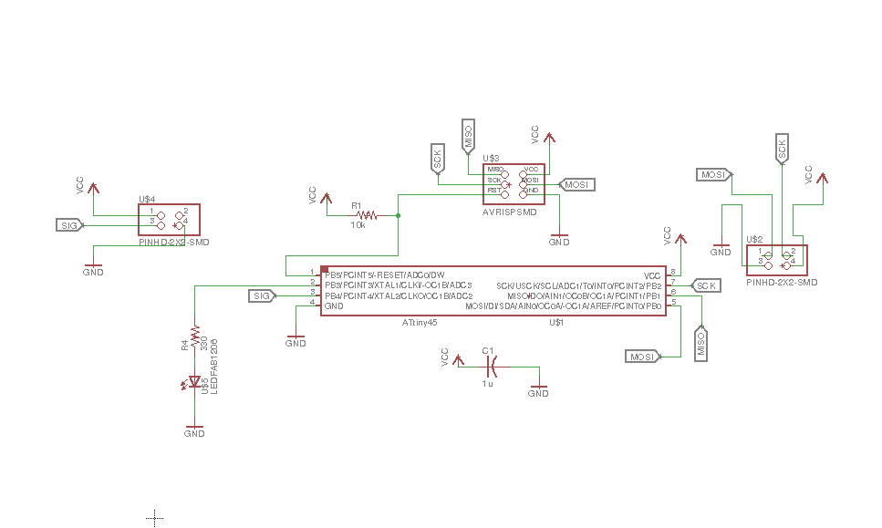
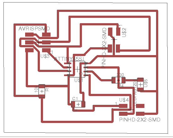
Design, Print & Solder Circuit Board
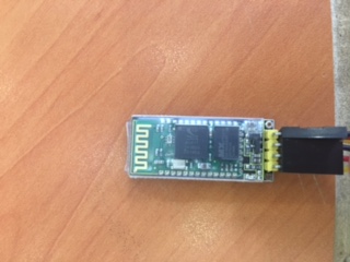
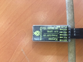
I had used in this week a circuit board installed with IR Sensor and LED "for future testing" in addition of making addition ports for bluetooth and TX & RX ports.
Writing the Code
In this week I used the library SoftwareSerial. unlike working on Arduino code where we can use Serial. We need to add SoftwareSerial library in order to work on ATTiny Controller.
Below are all the functions for SoftwareSerial:
SoftwareSerial.write
SoftwareSerial Constructor
SoftwareSerial.SoftwareSerial
SoftwareSerial.read
SoftwareSerial.println
SoftwareSerial.print
SoftwareSerial.peek
SoftwareSerial.overflow
SoftwareSerial.listen
SoftwareSerial.begin
SoftwareSerial.available
I will be utilizing some of the functions mentioned above.
Circuit Board Code:
#define rxPin 2
#define txPin 0
#define ir A2
SoftwareSerial mySerial(rxPin, txPin);
void setup() {
pinMode(ir, INPUT);
mySerial.begin(9600);
}
void loop() {
int sensorVal = analogRead(ir);
mySerial.print(sensorVal);
mySerial.println();
delay(100);
}"
I did not add FTDI on my circuit board to check the serial. Therefore, in order to check the reading from the IR, I brought an Arduino board and programmed BareMinmum code on it. Connect TX and RX from my board to Arduino board, and checked the reading.
Linking Circuit Board with the app
At last I connected the Bluetooth device with my circuit board. read the QR from android Phone. Search for the bluetooth signal and test the app
Downloaded files
Board Schematic
Board BRD
MIT APP IR.aia
Bluetooth Data Sheet