Mechanical Design And Machine Design
The official page of the group project is on the next link:
---> GROUP PROJECT<---
For this assigment, we have to:
- (DONE) Automate your machine.
- (DONE) Document the group project and your individual contribution
All the files created for this assigment can be found on the link bellow:
---> DOWNLOAD FILES<---
Have you:
- Explained your individual contribution to this project on your own website?
--> yes
Contribution
For this assigment we had to design and automate a machine. Every member of our group was assigned to an individual task, in my case I was in charge of the control of the motors and the logic of movement of the machine. The sections bellow explain the things I had to do for programing the machine.
Getting Started With Gestal Nodes
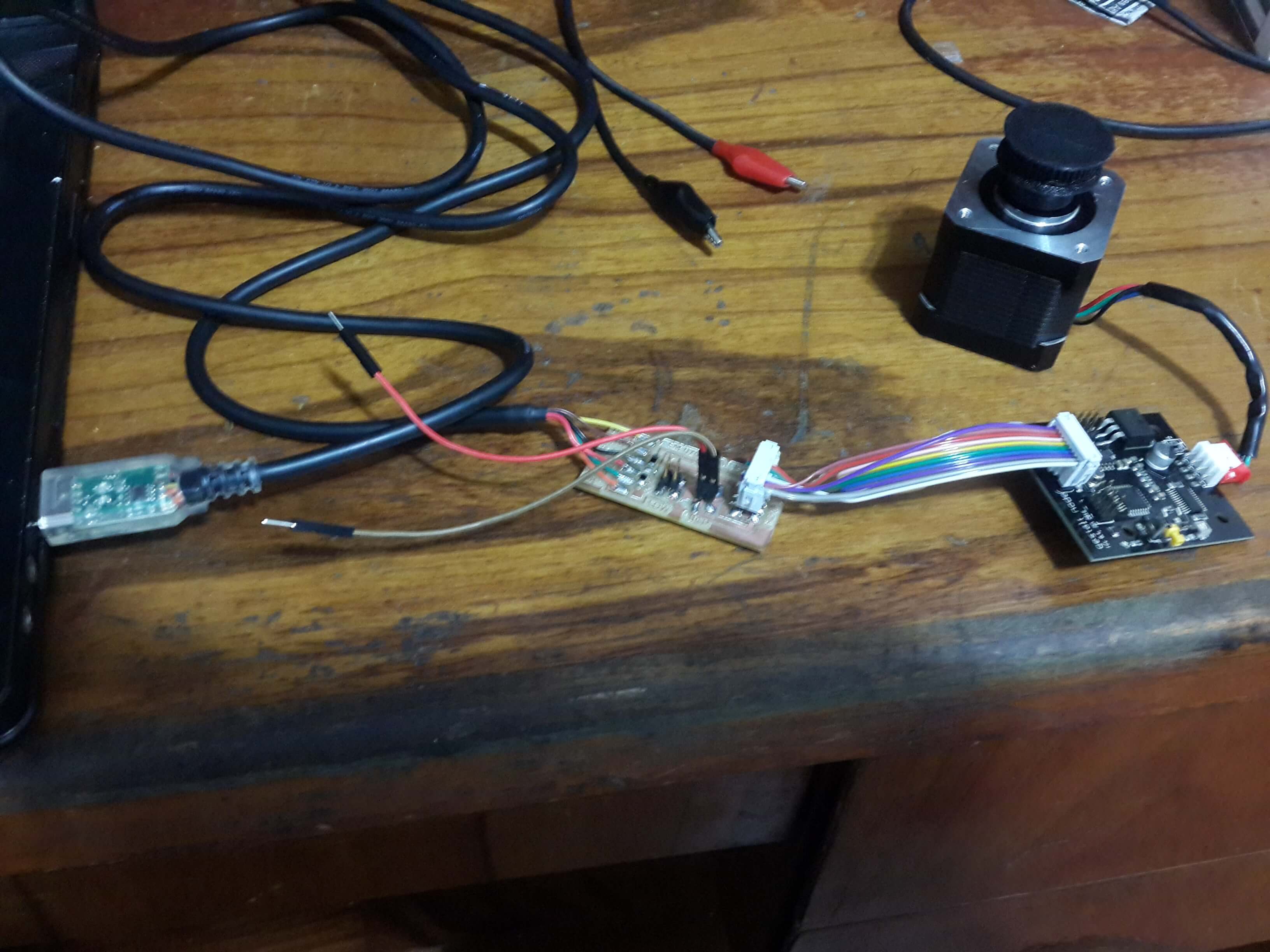
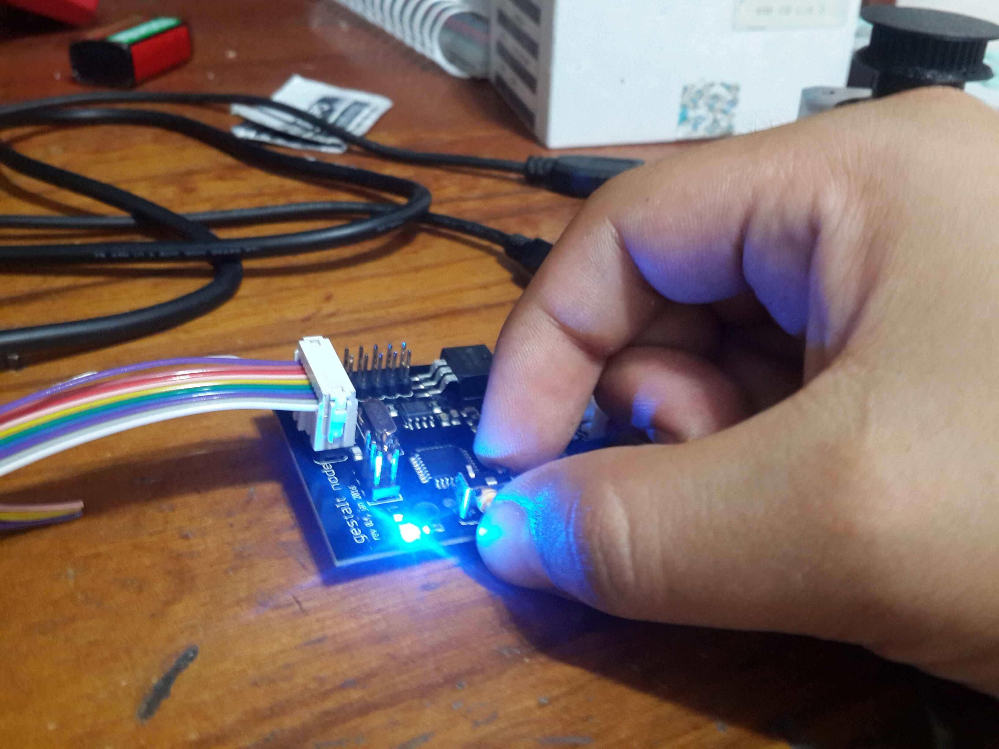
A gestal node is a piece of hardware, which consists on a microcontroller, a voltage regulator and a stepper motor driver. Its main function is to control a motor by commands sent by serial communication from a computer to the nodes.
a) From USB to Fabnet
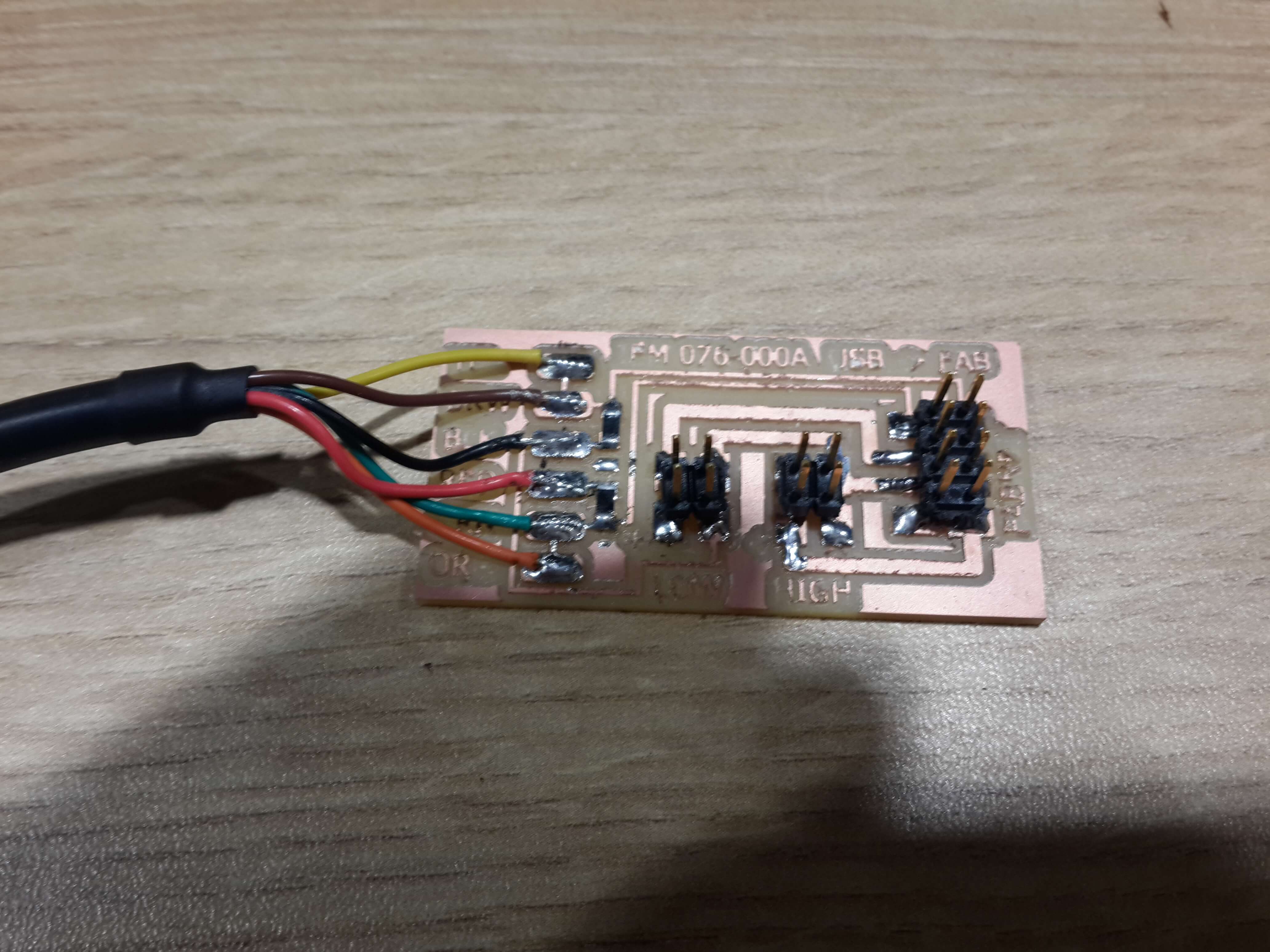
The gestal nodes have as input a Fabnet port which is a modification of the RS-485 port. So for this case, we needed an RS-485 version of the FTDI cable (USB to RS-485) to comunicate the pc with the gestal node.
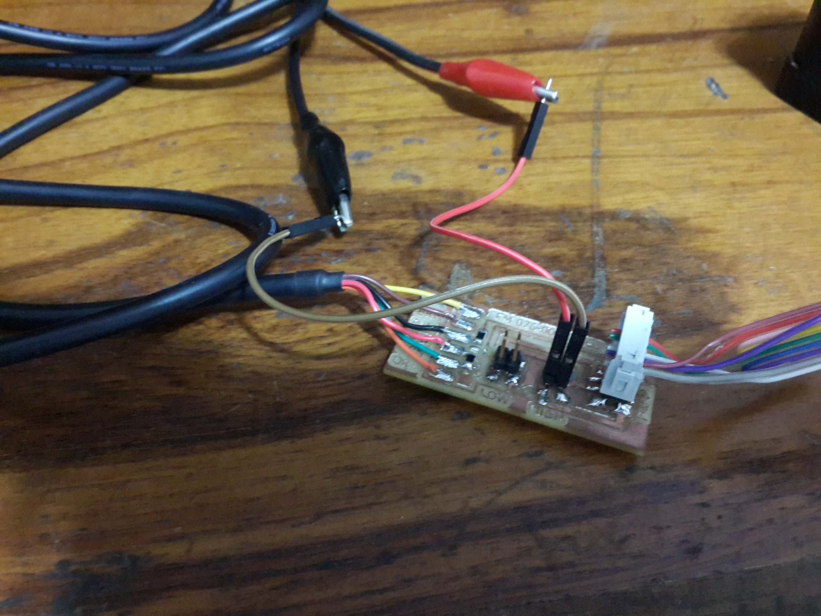
The RS-485 standard considers a Logical One when the differential of signal in the bus are greater than 200 mv and a Logical Zero when the differential of voltage is lower than -200mv; however, there is an umbiguity when the differential voltage of the transmision signals in the bus are between -200 mv and 200 mv. This usually happens when there are no signals on the bus, so for avoiding this amibiguity a pull down and pull up resistors are added to the transmision lines.
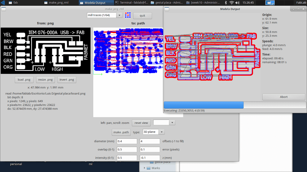
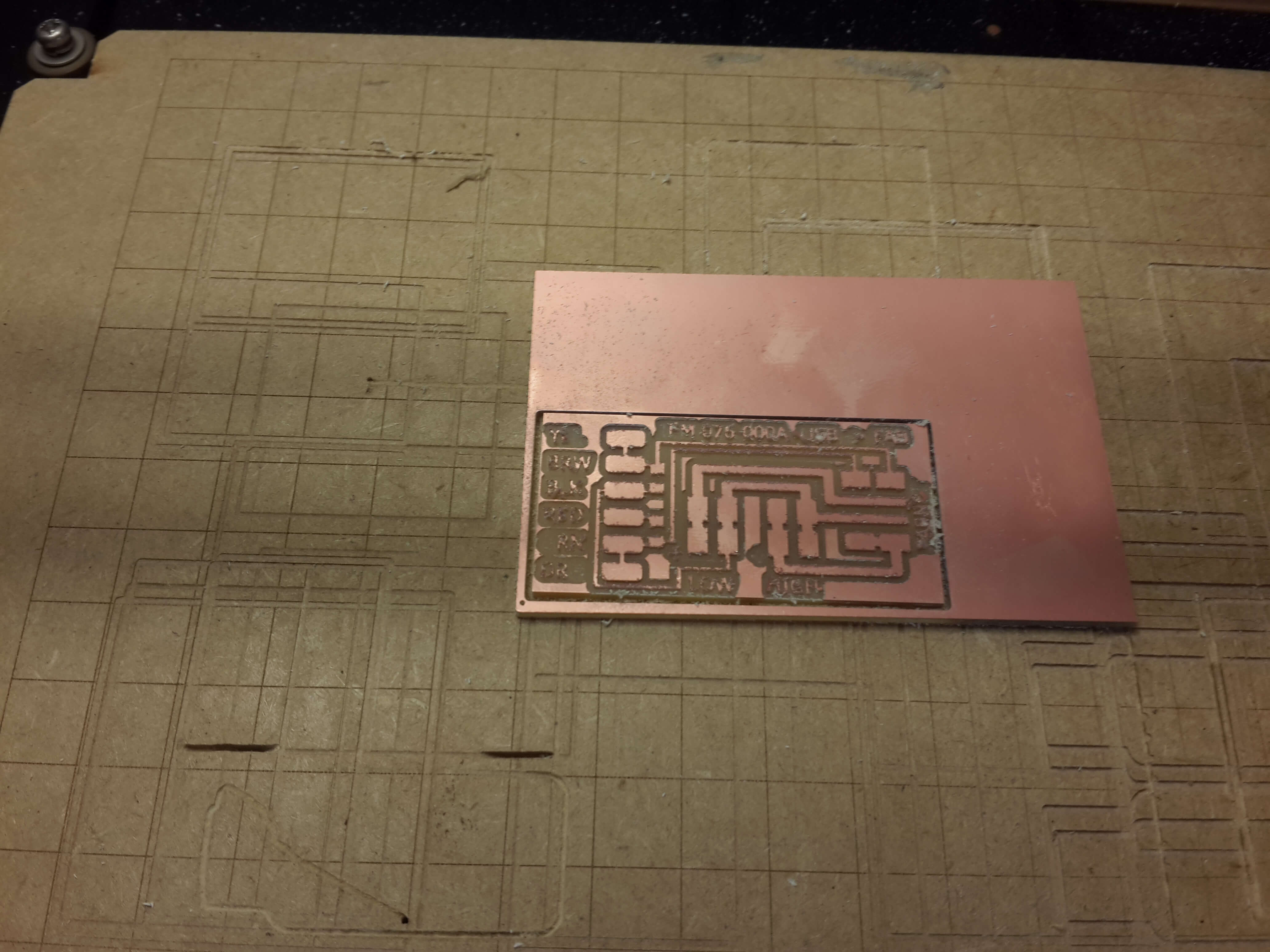
So, for adding this resistors and implementing the Fabnet port from the RS-485 output signal, I implemented a board which did that by doing the next steps:
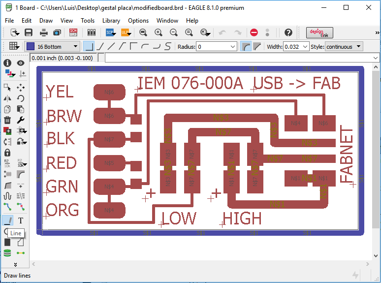
1. I downloaded the .brd file supplied on this tutorial.
2. I opened the file in EAGLE, clicked on the line tool, selected bottom (for drawing on the bottom layer), a line width of 0.032 inches and started to draw a rectangle around the circuit dimensions.
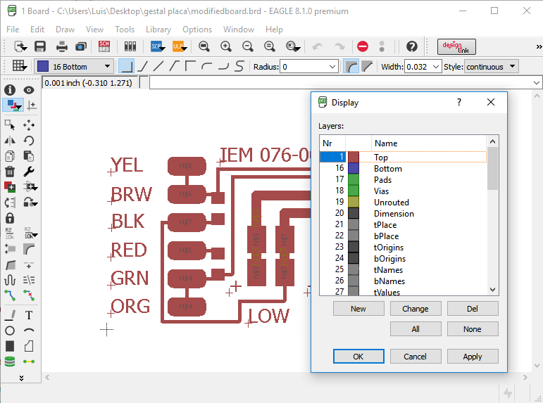
3. I clicked on Layer settings unselected all the layers and just left the top layer selected and clicked on apply.
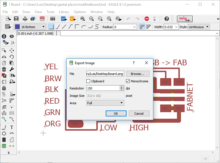
4. Then, I exported the image (File->Export->Image) in monochrome with a 600 dpi resolution.
5. Once again, I clicked on Layer settings unselected all and left selected only the bottom layer.
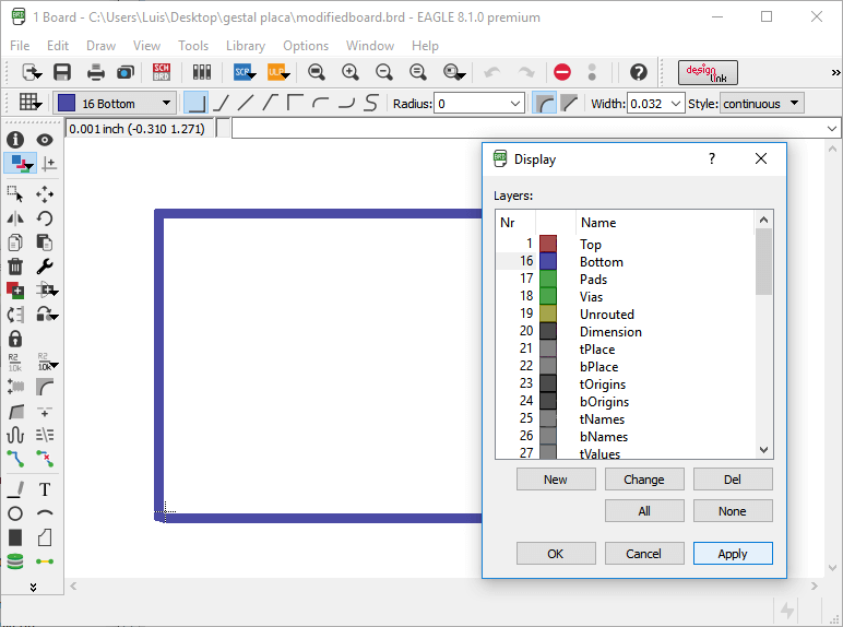
6. Then I repeated step 4.
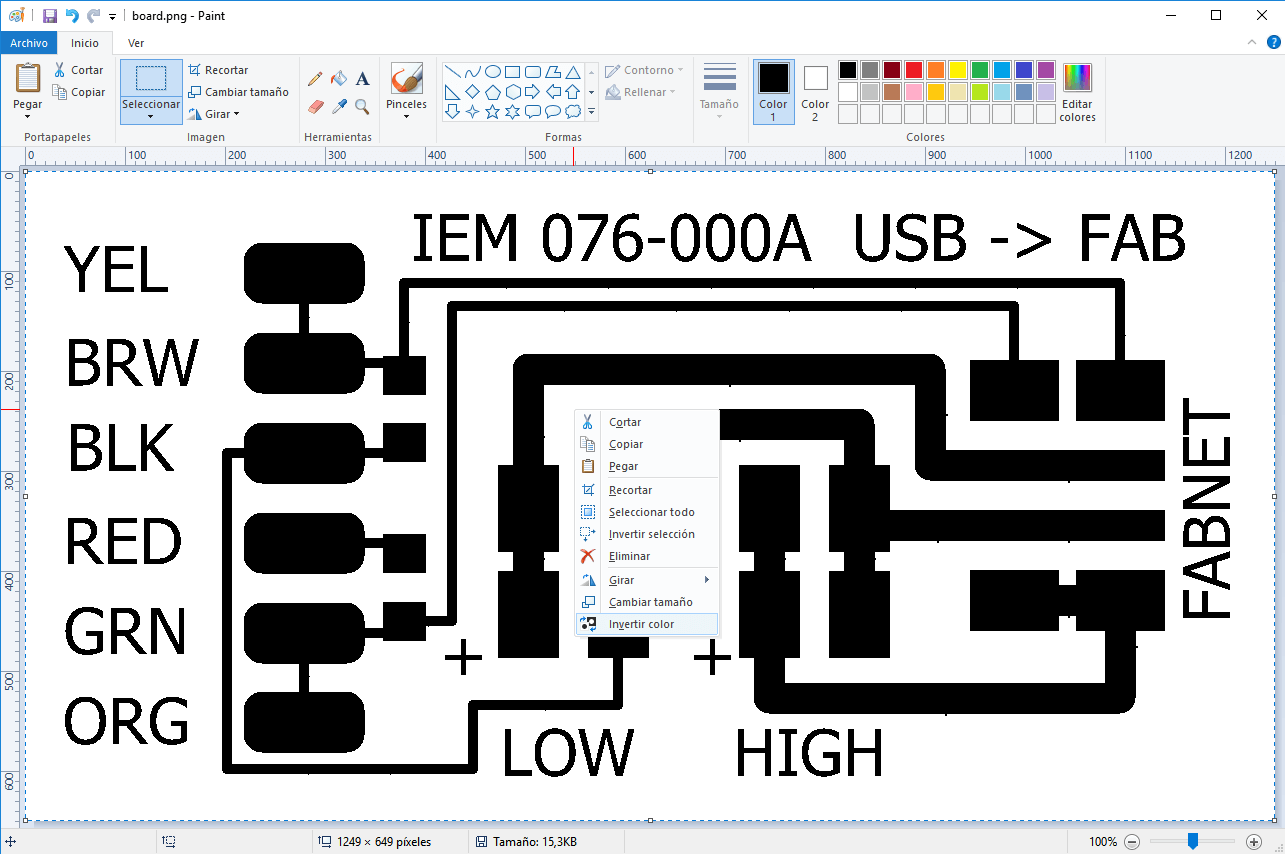
7. I oppened the image of the board in paint, selected all the image and inverted its color (right click-> invert color).
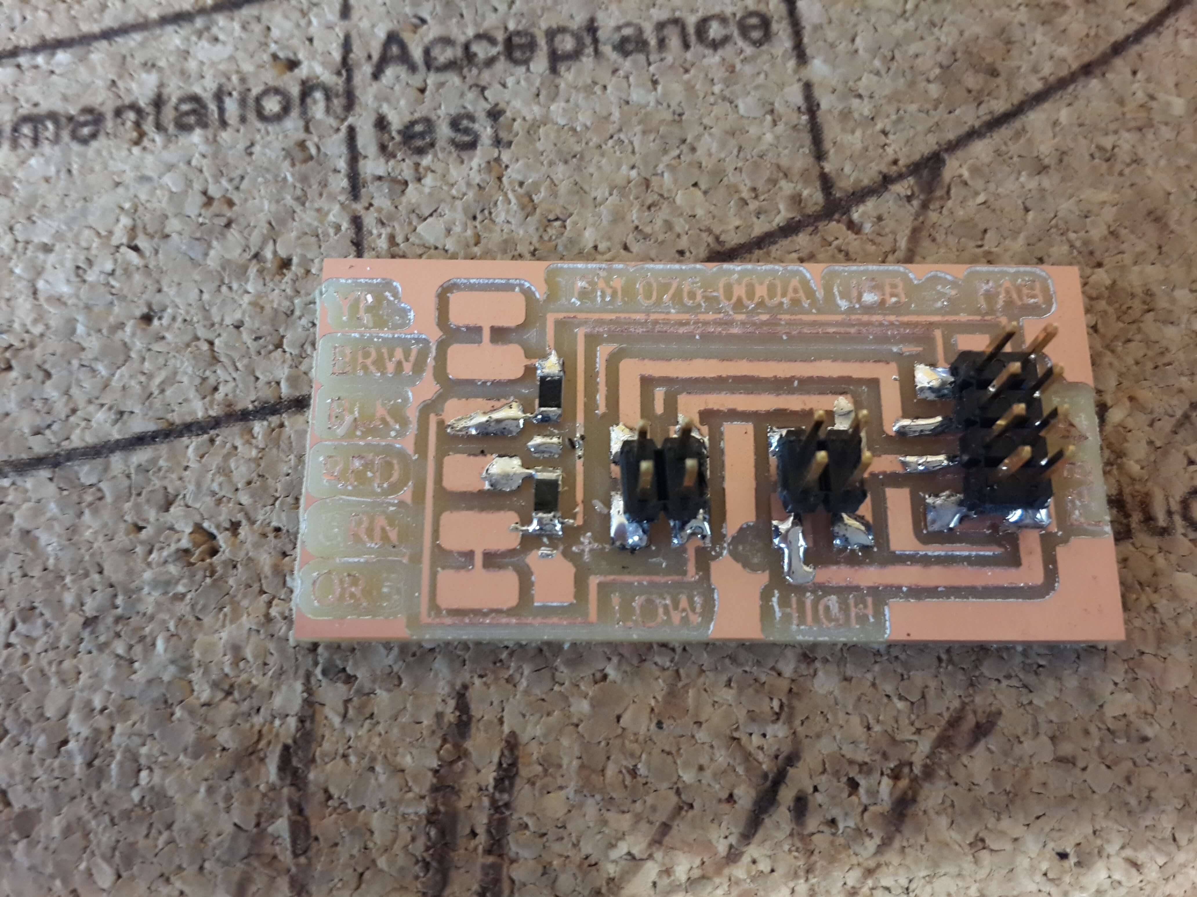
b) Programming The Gestal Nodes
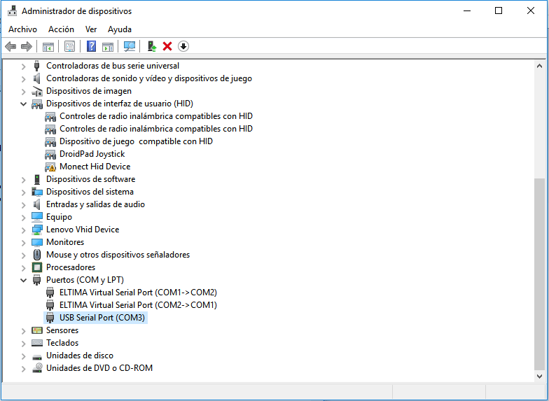
The Gestal Nodes can be controlled by a library written in python. So, before starting to use this library, its necessary to previously install a 2.X version of python on your pc. In my case I installed Anaconda which includes python and other packages which are usefull for me but not for this assigment. So if you do not need those packages, you can install only python. Once I had python installed on my pc i did the next steps:
1. I downloaded gestalt, which is a framework for building controllers, from github, und unzipped it.
2. Then, I oppened the windows command line and navigated with the cd command until I got in the gestal directory.
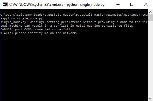
3. Then, I wrote on the command line the next command:
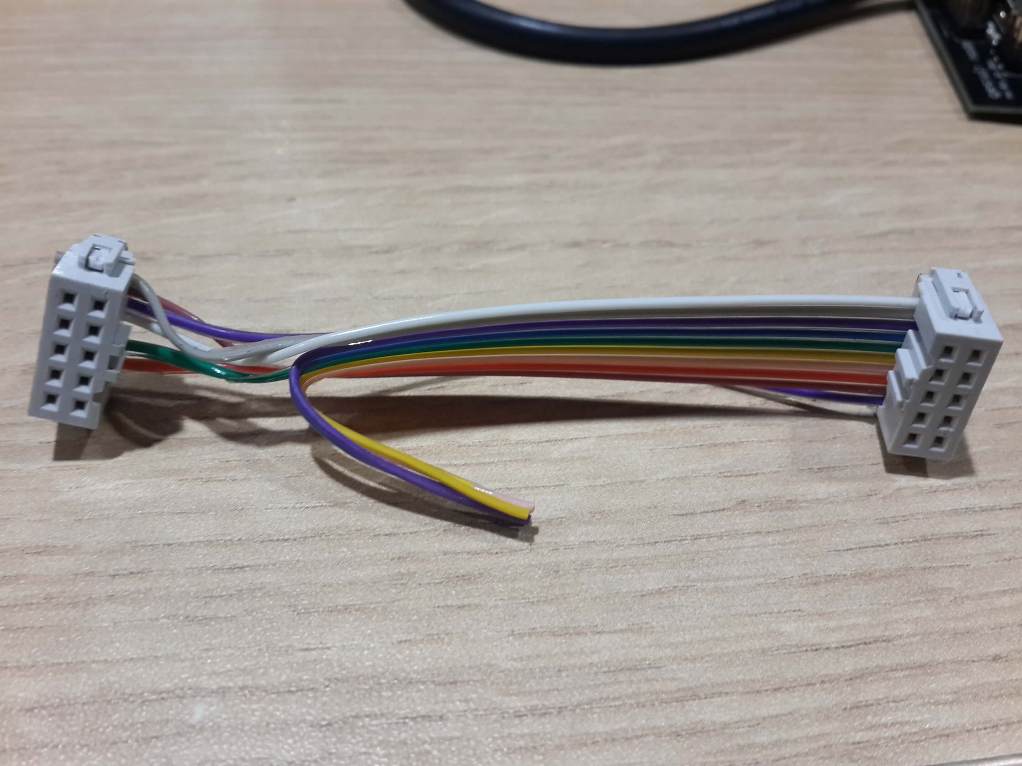
4. I connected the gestal node to the pc with the FTDI cable and the connector previously made and then the motor to the gestal node.
Programming the Machine
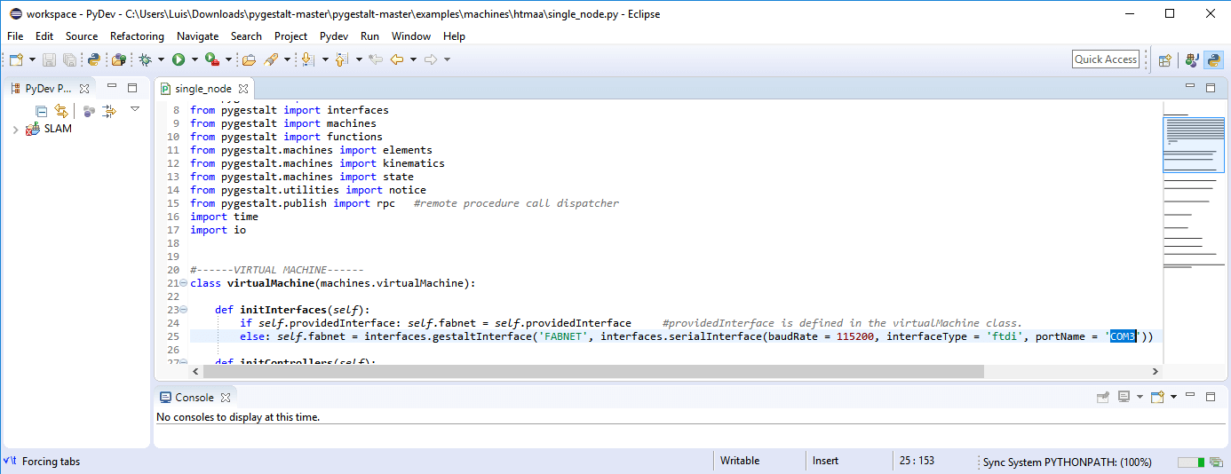
Knowing that our machine used two motors, I decided to modify the xy_plotter.py example, since this example was made for working with two motors.
So, before I started to modify this program, I had to understood it first. In general, this is how the program works:
The first part of the program consists on importing libraries and classes from the pygestal framework, followed by the importation of the clases time; which is used for declaring time delays; the class io, for working with data streams and the class threading for working with multiple threads.
The next part of the code redefines the class virtualMachine by adding methods to it. The methods added are the next ones:
a) initInterfaces: It initializes the serial communication between the PC and the gestal nodes.
b) initControllers: It defines the nodes to be used.
c) initCoordinates: It defines the number of coordinates and its units.
d) initKinematics: It defines the values necessary for doing the kinematics, like the number of degrees per step.
e) initFunctions: It defines the functions used by each node.
f) setposition: It overrides the value of the current position to one specified.
The programm continues by definig a variable with the virtualMachine class inside the main function, setting its velocity movement and the programming of the movements of the motors for the xy_plotter.
For our machine, we needed to control the motors idependently, instead of giving the coordinates in pairs like the example, so I modiffied the next parts of the code for having independent control of each motor.
1. I defined a compound node for each node inside the initControllers method.
self.yNode = nodes.compoundNode(self.yAxisNode)
self.positionx = state.coordinate(['mm'])
self.stageKinematicsy = kinematics.direct(1)
self.movey = functions.move(virtualMachine = self, virtualNode = self.yNode, axes = [self.yAxis], kinematics = self.stageKinematicsy, machinePosition = self.positiony,planner = 'null')
stages.yNode.setVelocityRequest(8)
As I stated before, we have two motors in the machine, one for rotating a plate and one for moving a cellphone along an arc. The movement of the plate is controlled by the joining of two gears, one under the plate and one next to that gear and attached to the motor.
Inside the initKinematics method there is a relation defined between the number of spins in the motor and the advance of the screw. So, I redifined this relation for rotating the plate. The relation between the diameter of the gear attached to the motor and the gear connected to the rotating plate was 1:4. So, I defined the advance in the screw as 90 (in our case it represent 90 degrees intead of 90 mm), which means that every 360 degrees spin of the motor makes the plate rotate 90 degrees (which is one fourth of 360).
Then, on the main function, I programmed the logic of the food scanner. Basically, the phone had to take photos of every angle of the fruit, so for doing this we rotated the disk by an specific angle and let a pause time for taking a photo, this movement was done until it reached 360 degrees. Once it comppleted a whole spin, the phone had to move up on the arc by some degrees and on that new position of the phone, the disk had to rotate once again with time pauses for the photos. When all the photos where takenand the phone was on a 90 degree position on the arc, the phone returned back to its original position, which was 0 degrees on the arc.
In code this was done in the next way:
1. I calculated the angles where the arc and the disk should pause and putted each of them in a list of lists.
nshots=3; # number of pauses of the disk on its way to 360 degrees
dangle=360/nshots;
movi= range(0,360+1,dangle)
movesx = []
for i in movi:
movesx.append([i])
# Phone
viewpoint=3; # number of pauses of the phone on the arc
dangle=90/viewpoint;
movi= range(0,90+1,dangle)
movesy = []
for i in movi:
movesy.append([i])
2. Then, I called the move function for each node in a double for loop which got the angles of pause of each motor.
self.stages.movey(my,0)
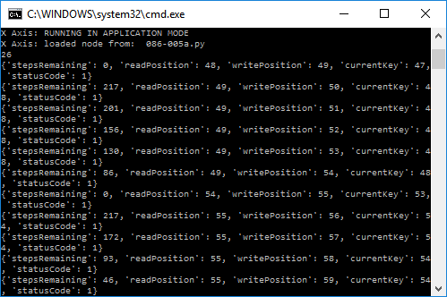
status = self.stages.yAxisNode.spinStatusRequest()
# This checks to see if the move is done.
while status['stepsRemaining'] > 0:
time.sleep(0.5)
status = self.stages.yAxisNode.spinStatusRequest()
for mx in movesx: # Disk
stages.movex(mx,0)
# This checks to see if the move is done.
status = self.stages.xAxisNode.spinStatusRequest()
while status['stepsRemaining'] > 0:
time.sleep(1)
status = self.stages.xAxisNode.spinStatusRequest()
3. Since the last angle of rotation of the motor was 360 degrees and the gestal framewrok did not recognize it as zero degrees I had to add a line after the internal for loop of the code above, which setted the virtual position of the motor as 0 degrees
4. Finally, I had to return the phone to the zero degree position on the arc, so I called the move function and assigned it as position [0].
status = self.stages.yAxisNode.spinStatusRequest()
# This checks to see if the move is done.
while status['stepsRemaining'] > 0:
time.sleep(0.5)
status = self.stages.yAxisNode.spinStatusRequest()
This is how the move look.