To be honest i think this was the hardest week for me. i felt i was lost, not used to Git and coming up with a cool website idea in a week is pretty hard so i'm gonna try my best to help everyone get over this part ^^.
So after looking through all these links we can start building our website.
First: you can't build a website from scratch in a week. luckely we have
Bootstrap
which will make your life WAAAAAY easier. Pick a website template from StartBootstrap or any similar websites that give free templats then download it.
Second: learn a little bit about coding HTML, CSS and bootstrap. there are some amazing websites like
CodeAcademy
which has a built in text editor, live preview and tips for each lesson.
or you can learn from
W3Schools
which is also great for new comers *like myself* to the world of making websites
Third: you need to have a text editor. I used Note++ first which you can download from
Here
but then i switched to Brackets which is more interactive and has "live preview" of what you are coding so you won't be switching back and forth to save and refresh your browser to see the changes. basicly its better for working on website (for me at least ^^ ). you can download it from
Here.
It also has a great interface. Some of my friends work with "Sublime" i personally never tried it but you can give it a go. and if you know something easier or better please let me know ^-^ .
After you're finished making your website pretty useing Photoshop, illistrator, Sketchbook or maybe google for preset icons you can move to the next step *which was the hardest for me By the way :D *
WORKING WITH GIT (x_x)
The first thing you need to start working is getting your SSH key. i did it by downloading Git Bash and typing 2 simple commands.
the first one is "" (without the quotation marks) which shows you if you already have a SSH key or not. if you have a SSH key you will get a long string then you can copy that and put it in your profile settings.
the second one is "" (also without quotation) which makes a new SSH key if you don't already have one and after you are done you can put it in your settings.
A very Useful link for working with Git and getting started is
This one it will help you understand how to start for FabAcademy and How to setup your Own Folder for future projects. Which was made by
Matthieu.
So thank you very much Matthieu you helped me a lot ^-^
if you are still Confused you can always ask for help. which is the best thing about the Makers Commuinty and i wouldn't be making this website right now without them ^-^.
Week 2:Computer Aided Design
Week 2 is by far the week i had Fun, Enjoied doing the assignment and very happy with the outcome.
it will need a little bit of previous experince but i'm sure you will have fun trying new stuff. so lets jump in ^^
What you will need for this assignment.
Sketch book and a pencil
2D sketching program
3D Modeling program
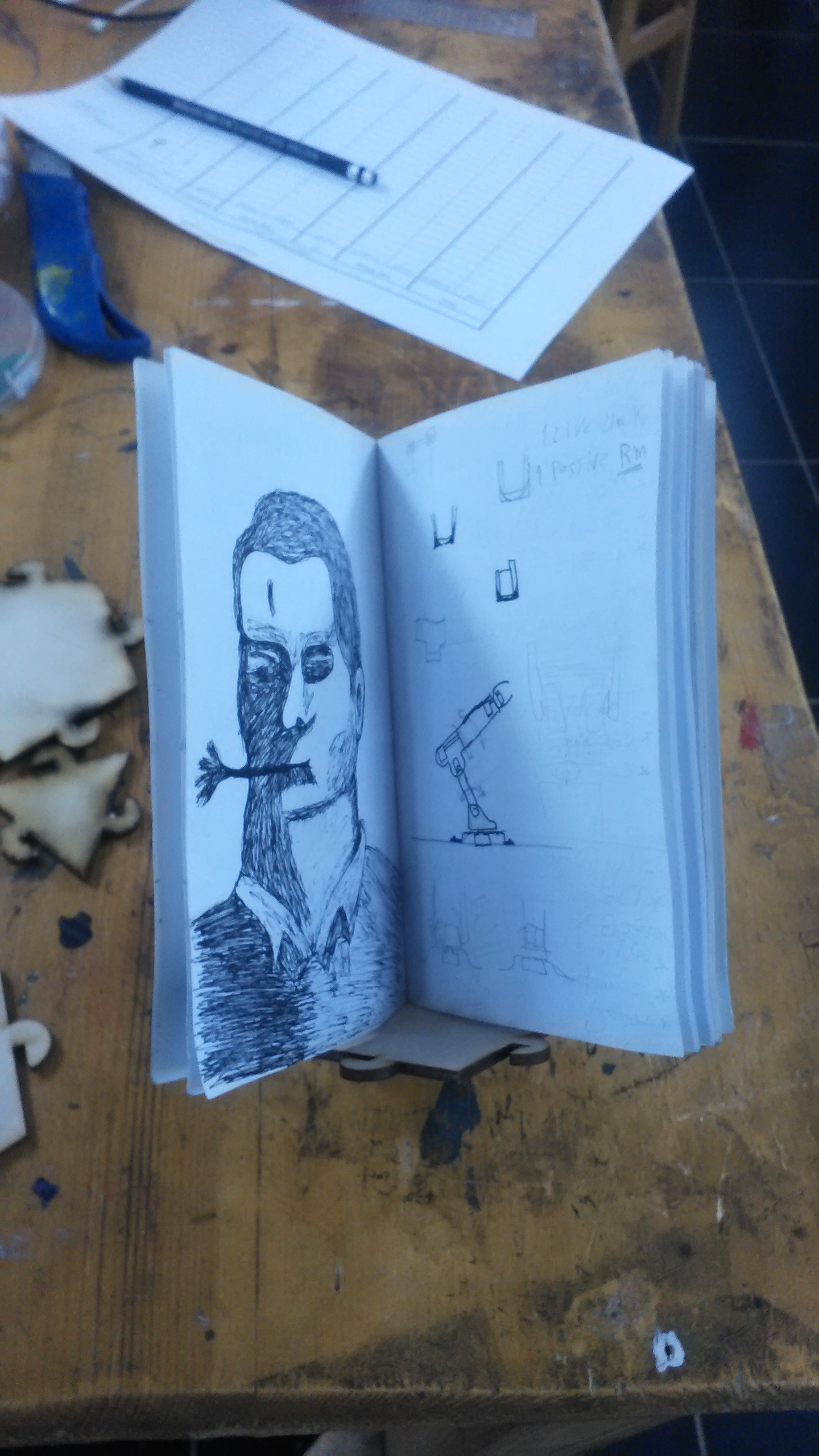
first we will start by Rough sketching the idea.
(don't worry if it sucks at first, it always does xD )
after knowing that i suck at Rough sketching as usual i got my ruler and began to sketch for real.
now its time to know how my mechanism will work and get a good idea of how it looks inside.
now we need to get some measurments because this sketch could be 80 Meter or 80 Cm so we need a 2d Sketching program to start laying our measurments and our model profile i'm working on Solidworks just because this is the one i have most experince with. BUT i started learning Fusion360 and i like it a lot so far plus its free but time didn't serve me so i had to work with Solidworks for now. it will be easier for me to work with Fusion since it already has a CAD-CAM add on and my project will be done on a CNC router.
first i will start with the "Bench" part of the bench.
then we need to give it some legs or support of some kind
this is how it looks after Extrusion.
Shaping the legs to the shape we like.
and cut the rest with Extrude cut.
now i need to set some groovs for the screw and motor mount. but i won't be drawing the screw and motor in this assignment that will be for the final project so make sure to check that out ;).
Cut again.
AAAAAAAAAND we are done, HORAAAAY finally.
hope you like it and please tell me if you have any ideas to make it better or easier.
i also hope it helped. see you on the next assignment ^_^ .
to download the Design in SLDPRT format click Here
Week 3:Comupter Controlled Cutting
OKAY. with the new concept of "making my documentations easy that even my grandma can do everything in it" in mind. I started week 3 and it was a little bit more challenging for me. The whole idea of creating a Kit took some time for me but after brain storming and getting some ideas rolling it gets waaay easier.
lets get started. ^^
What you will need for this assignment.
Design Software (whatever you like)
laser cutter and vinyl cutter
A LOT OF TIME TO THINK
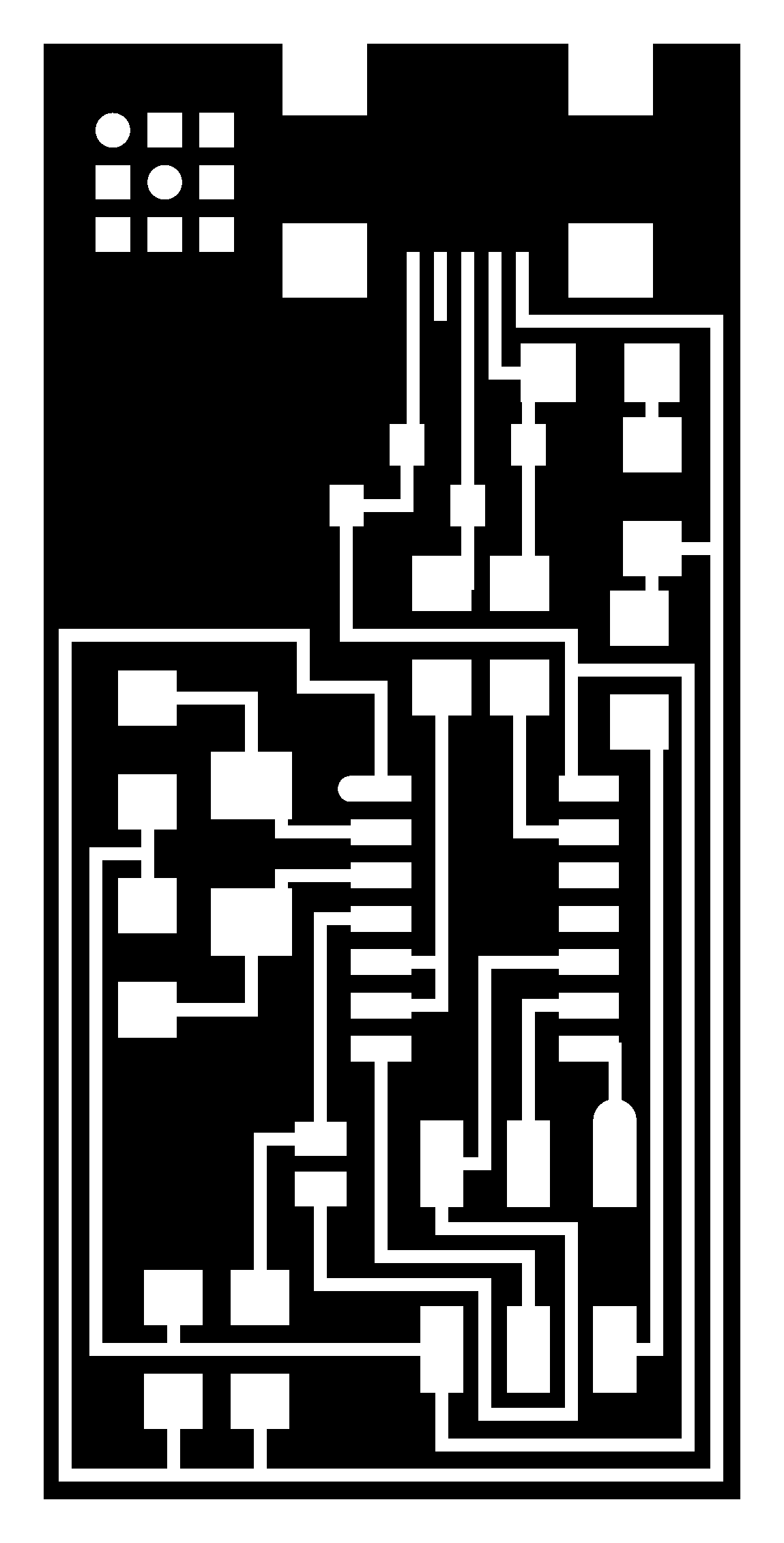
first we gonna make a sticker on the vinyl cutter which is for me a Bitmap logo of my project "voodoo bot"
i imported my image into Roland CutStudio from the file menue ->import then pick your picture and move it to place
for the machine to understand where to cut we have to make an outline of the image and we do that by Right clicking on it then selecting Image outline...
i adjusted the slider until all the pixels i wanted are showing in the preview and then clicked on extract countor lines
(NOTE: that when you go to lighter the image fades away more and darker creater more pixels which are not necessary)
press ok then drag the outline away from the original picture.
now delete the original picture and adjust the place and size of the outline.
(NOTE: hold SHIFT to keep the proportions of the image)
from the toolbar click properties to see the final dimensions of the sticker and adjust them if you want.
click on cutting, select the model of your Vinyl cutter the click OK
and we are done with the software.. now its time to make it.
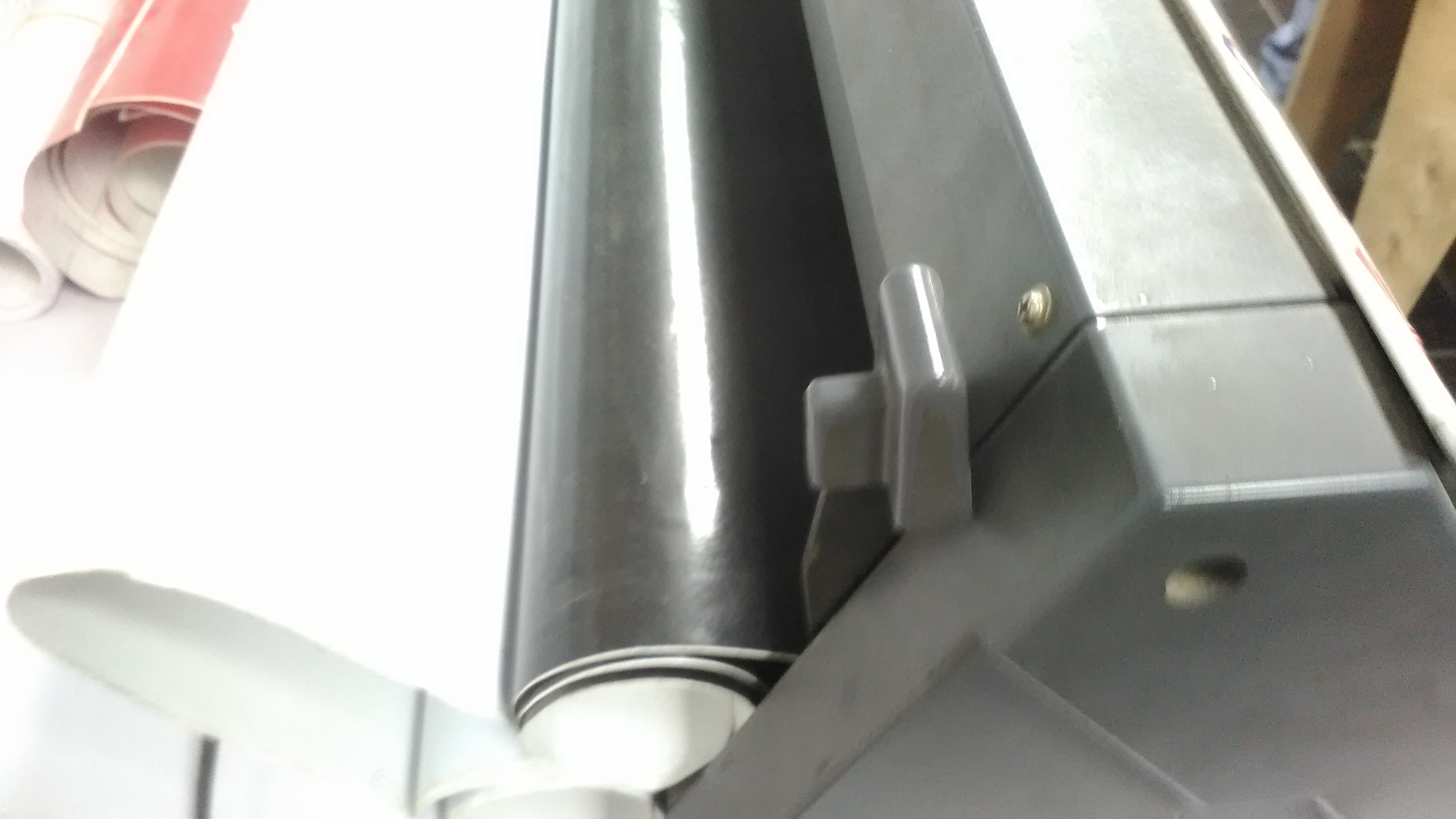
i powered up the machine the loaded the Vinyl roll into the machine from the bach side then secrued the roll by pulling up the Grey lock
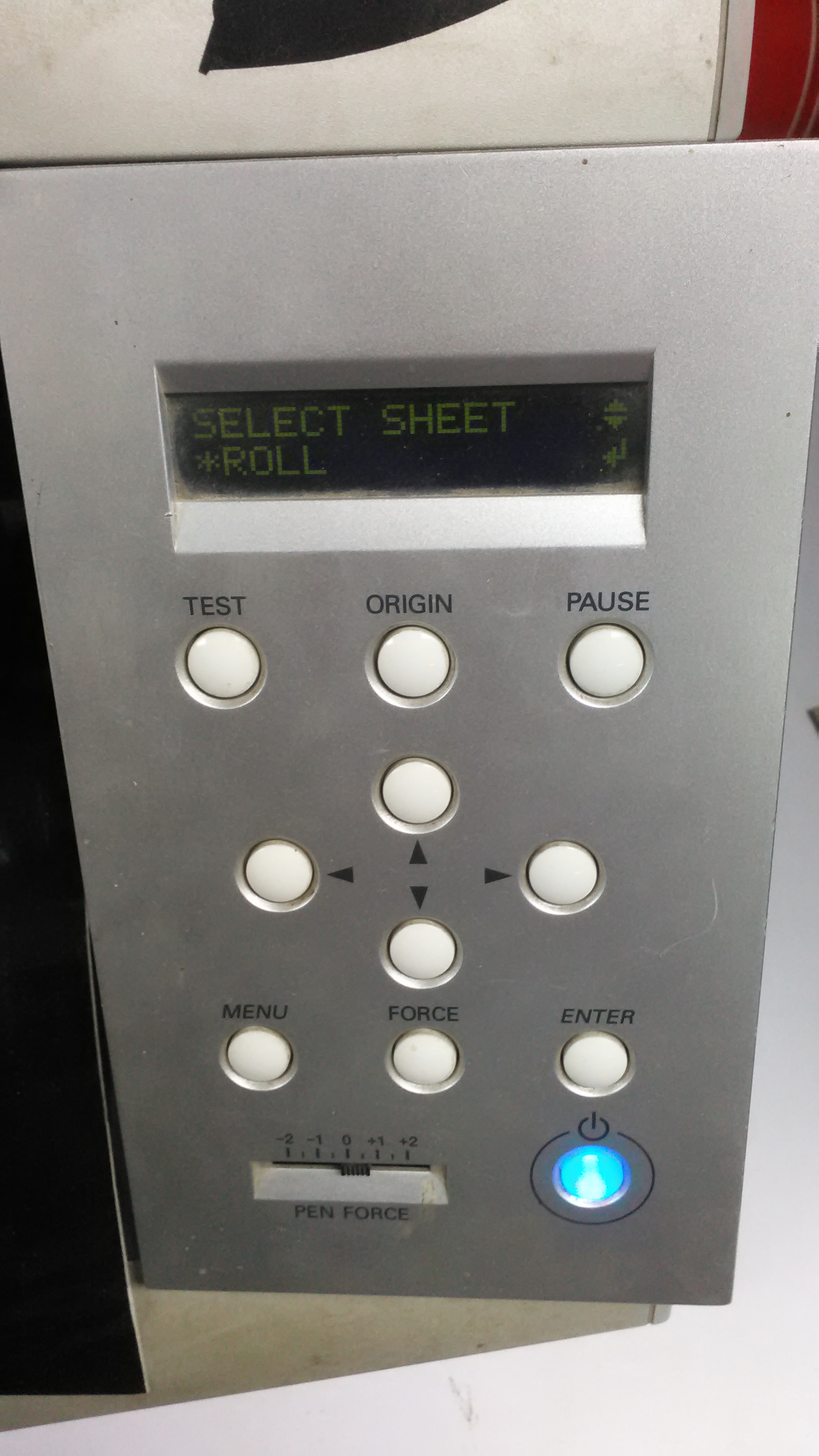
select that its a Roll from the control panel
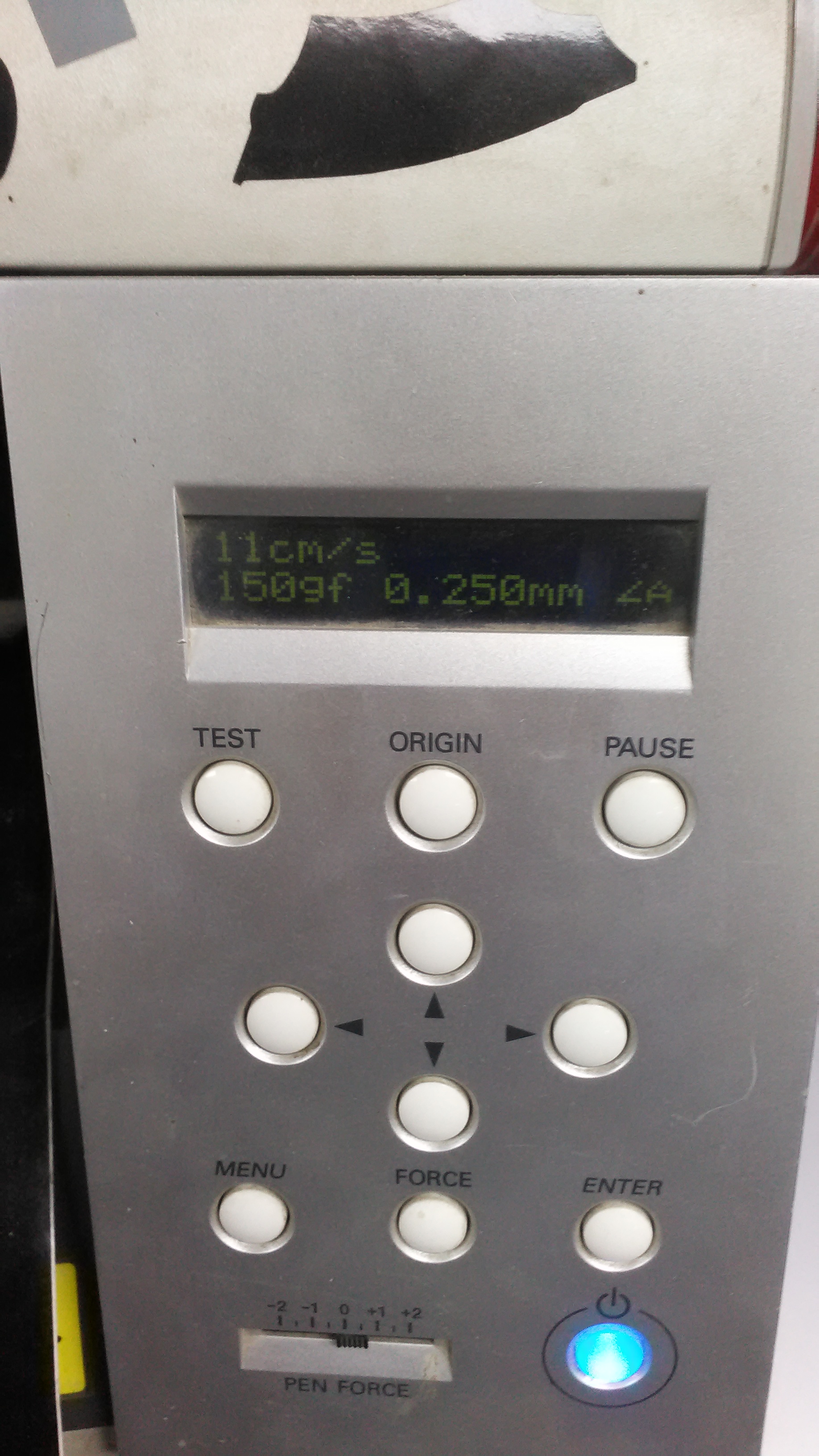
Set the Force and speed of the cutter then press print from the Software
and this is the final Result
Now its time to design a construction kit that can be fabricated on a laser cutter.
i got the idea after alot of time thinking of a cool and new way to connect pecies together. i finally came up with the idea of connecting polygons together by slotted circles on each line of the polygon. so i opened fusion 360 and started working.
i started a new sketch from the top view with a triangle and making circles on the middle of each line in that triangle.
now its time to make it parametric. from the modify menu select change Parameters
(NOTE: you can click the upward arrow next to it to get a shortcut on the top toolbar)
after opening the parameters menu select the plus sign next to "User Parameters"
Spicify the name of the parameter and the unit and comments to understand what this parameter is for. the most important thing is the Expression which determins the value of that Parameter it could be an Equation or a typed value. then press OK.
now instead of typing the value of the dimension you can type the name of the Parameter and when you change the value of that Parameter it changes all dimensions with that Parameter name.
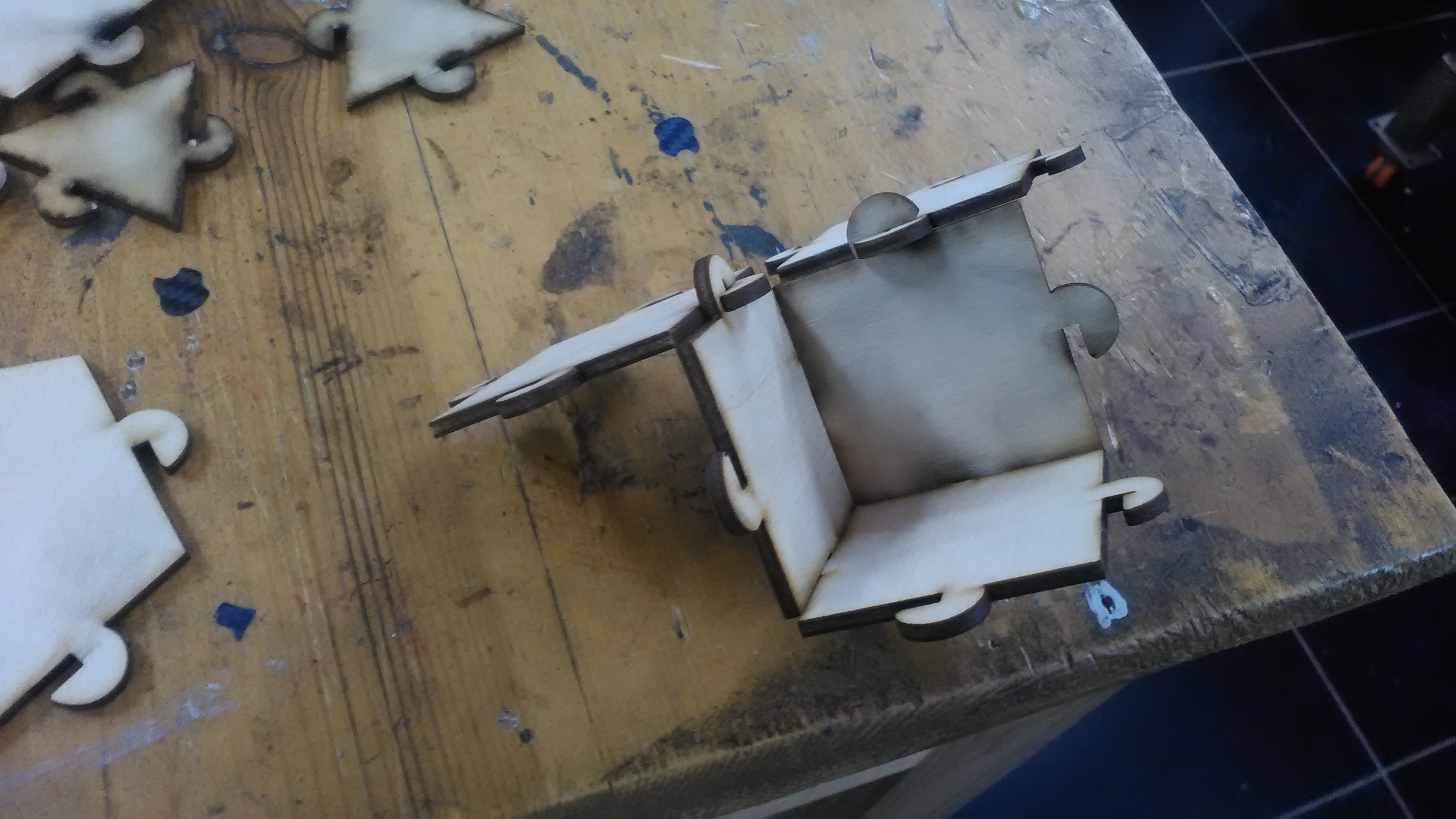
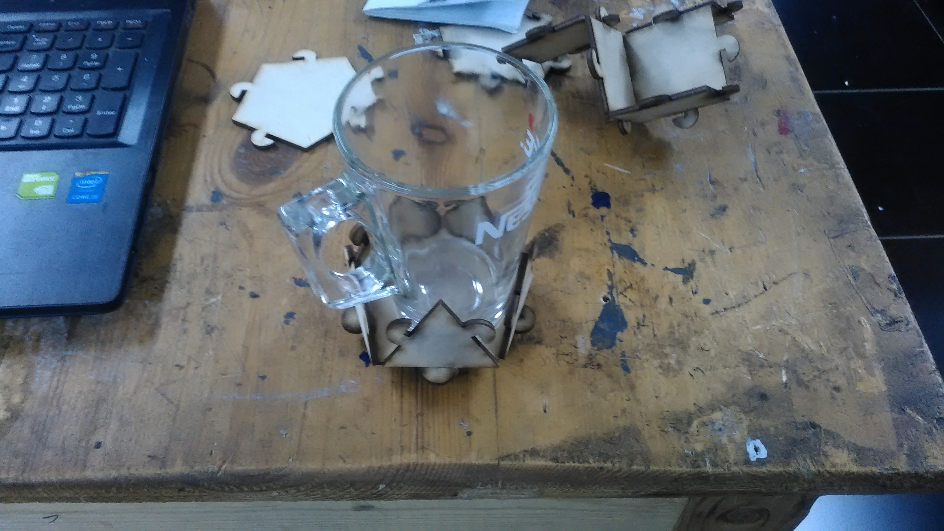
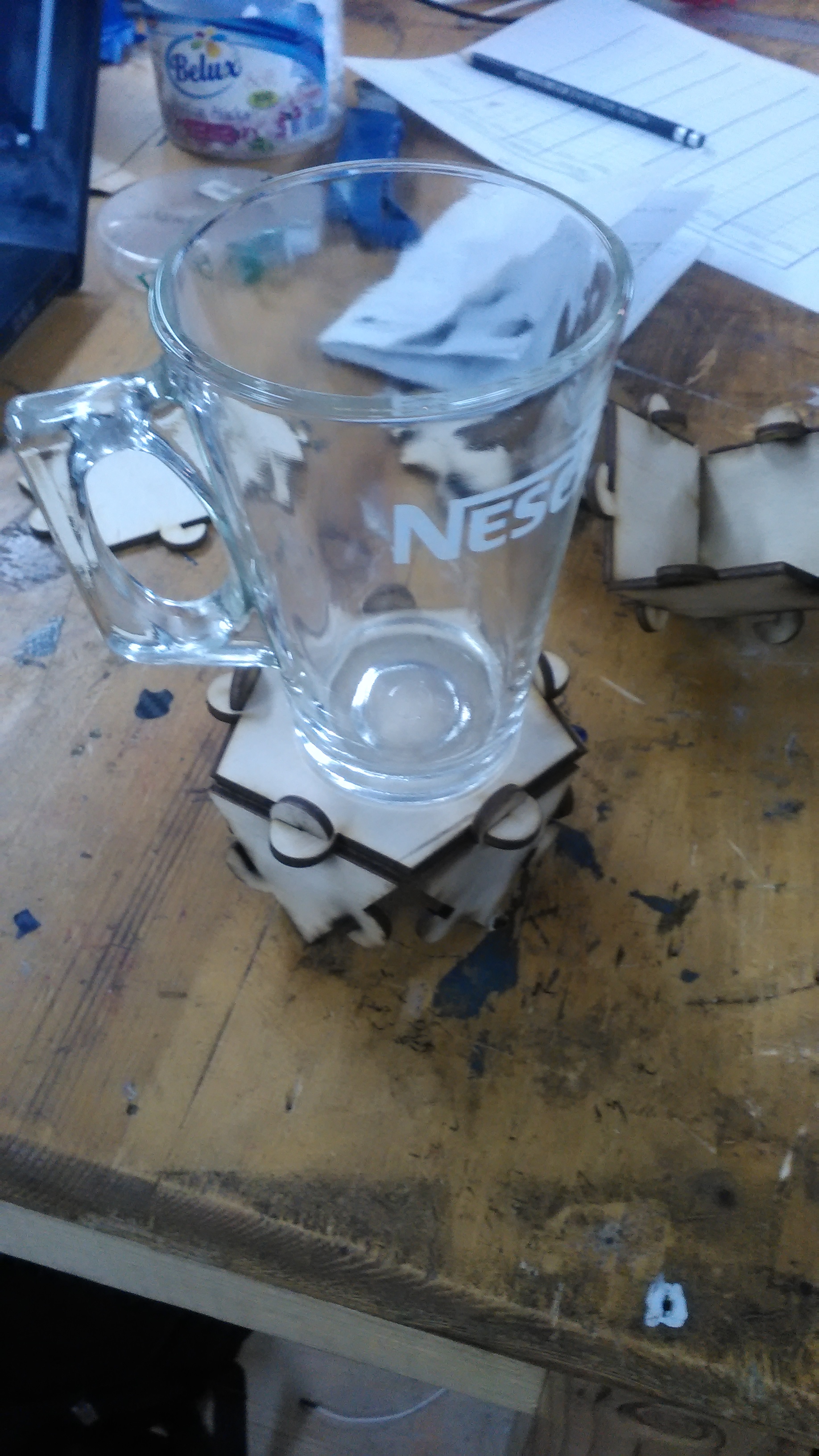
i redone the previous steps for the next 2 sketches for a Rectangle and a Pentagon. and these are the results.
after that i sent the files to Coral Draw and used the RDworks Add on for coral to send the designs to the machine.. and here is the final result
Make an in-circuit programmer by milling the PCB (program it, so that you can use it to program your board in Electronics Design week, and in other weeks)
What needs to be done
make rml Files
operate the Modela
Program The FabISP
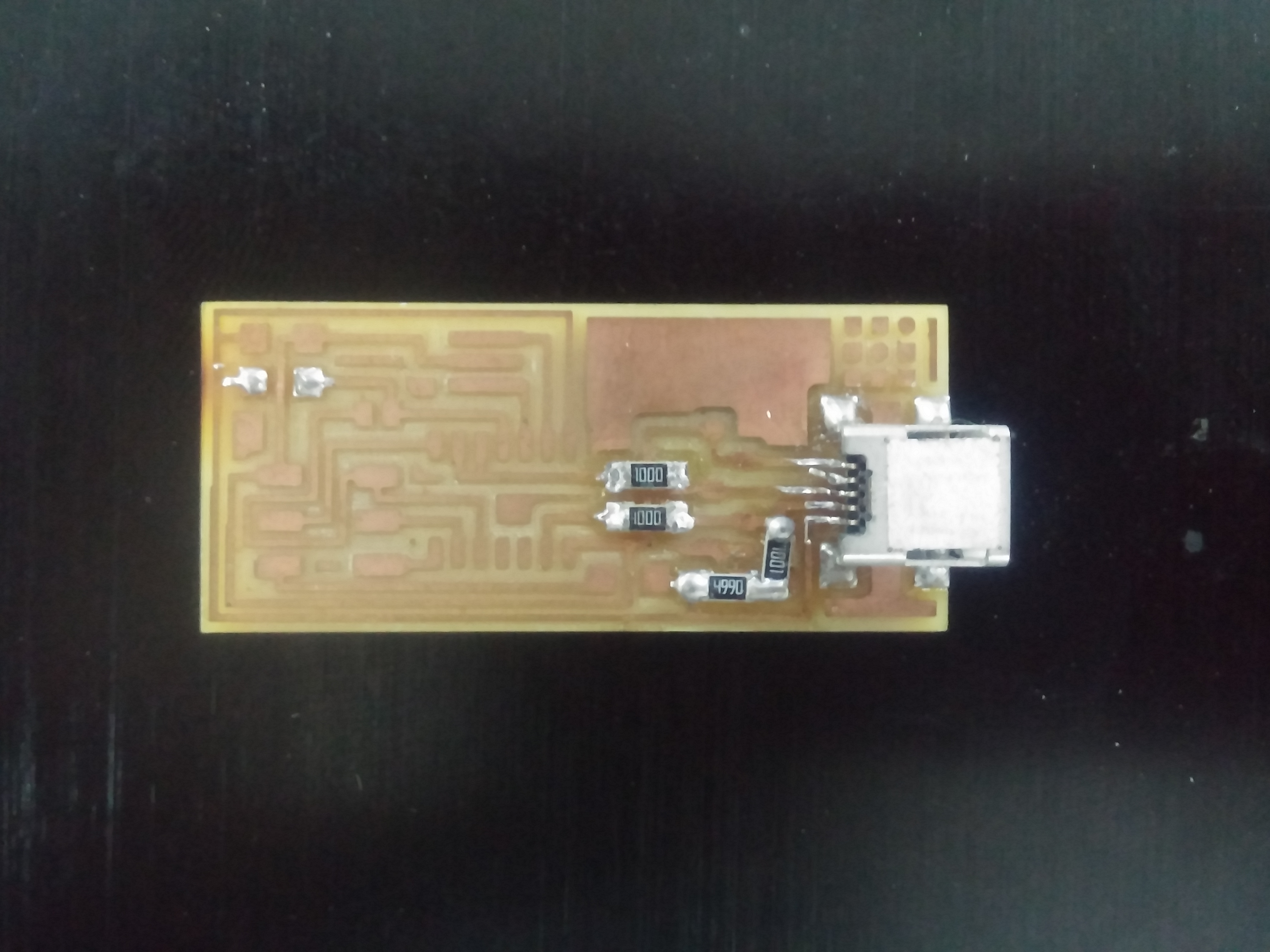
First i got the PNG files from Tutorial Page and downloaded them. Traces
And
Outline .
i opened Fab Modules and imported the PNG file. then i selected the Output file for my Machine and the wanted process (eaither Traces or Outline).
Then i modified the model of the machine, Home Position and set the Z manually.
Press Calculate and the path will show.
after the machine is done i did the same for the Outline but instead of Choosing Traces (1/64) i Chose Outline (1/32). then pressed Calculate.
i Forgot to take picture while milling because i was so excited to solder it and program it. that excitment went away extremely fast when i hit the wall of SMD soldering.
Design and 3D print an object (small, few cm) that could not be made subtractively
3D scan an object (and optionally print it)
What needs to be done
Show how i designed and made my object and explained why it could not be made subtractively
Scanned an object
Outline problems and how i fixed them
Include my design files and ‘hero shot’ photos of the scan and final Object
I took me some time to think about something that can't be done with 5 Axis milling machines other than enterlocking links or a ball inside another ball. i finally decided to make a Passive sound amplifier for my phone.
It's like a Gramophone with 2 sides and a place to put my phone so it can amplify the sound coming out from my phone's speakers (its something like This)
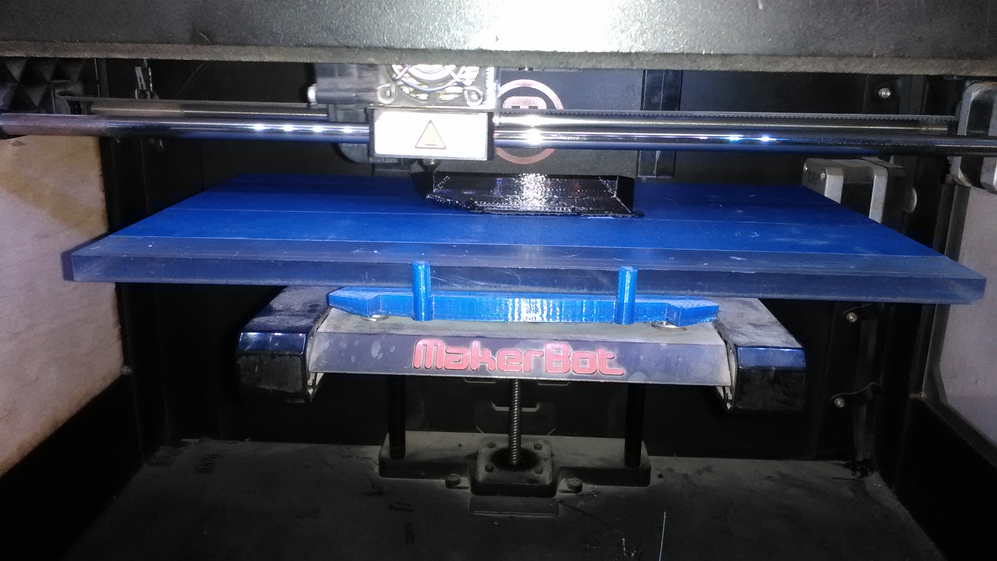
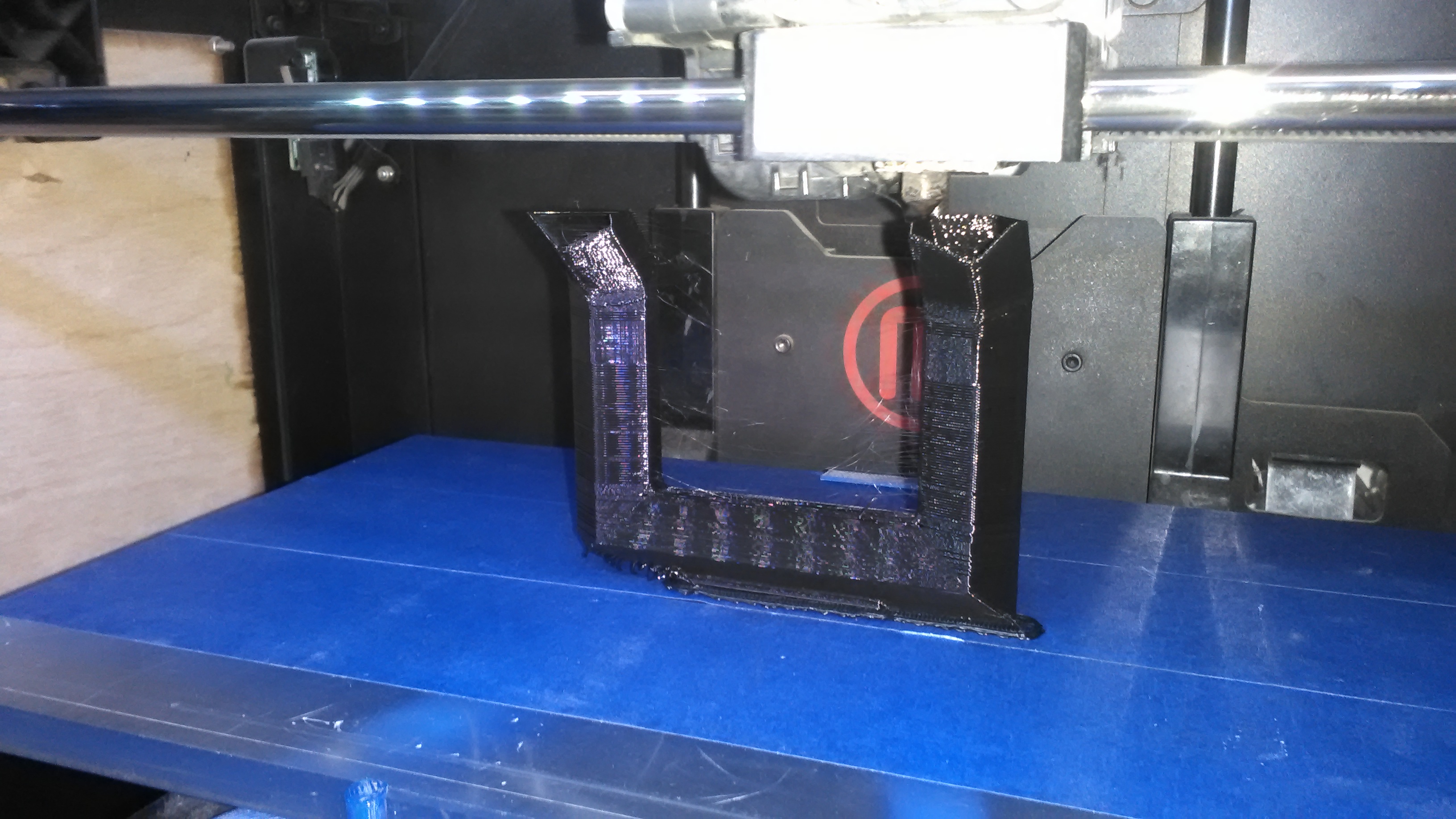
so i started my Own design on SolidWorks with the Design rules of our printer (MakerBot Rep2).
Design Rules
Preferred maximum Angle is 45 degrees (can be more but not stable)
Nozzel heat 230 degrees
Bridging 2cm without hanging (a little bit of hanging plastic with more distance)
i didn't care about the dimension tolerance because i couldn't use the part anyway but it has a 0.2 tolerance when heat changes while printing
I started something new to me which is 3D sketching. its a normal sketch like every CAD software but on 3 Axis at the same time so i can make lines come in different angels. this Tutorial Helped me alot
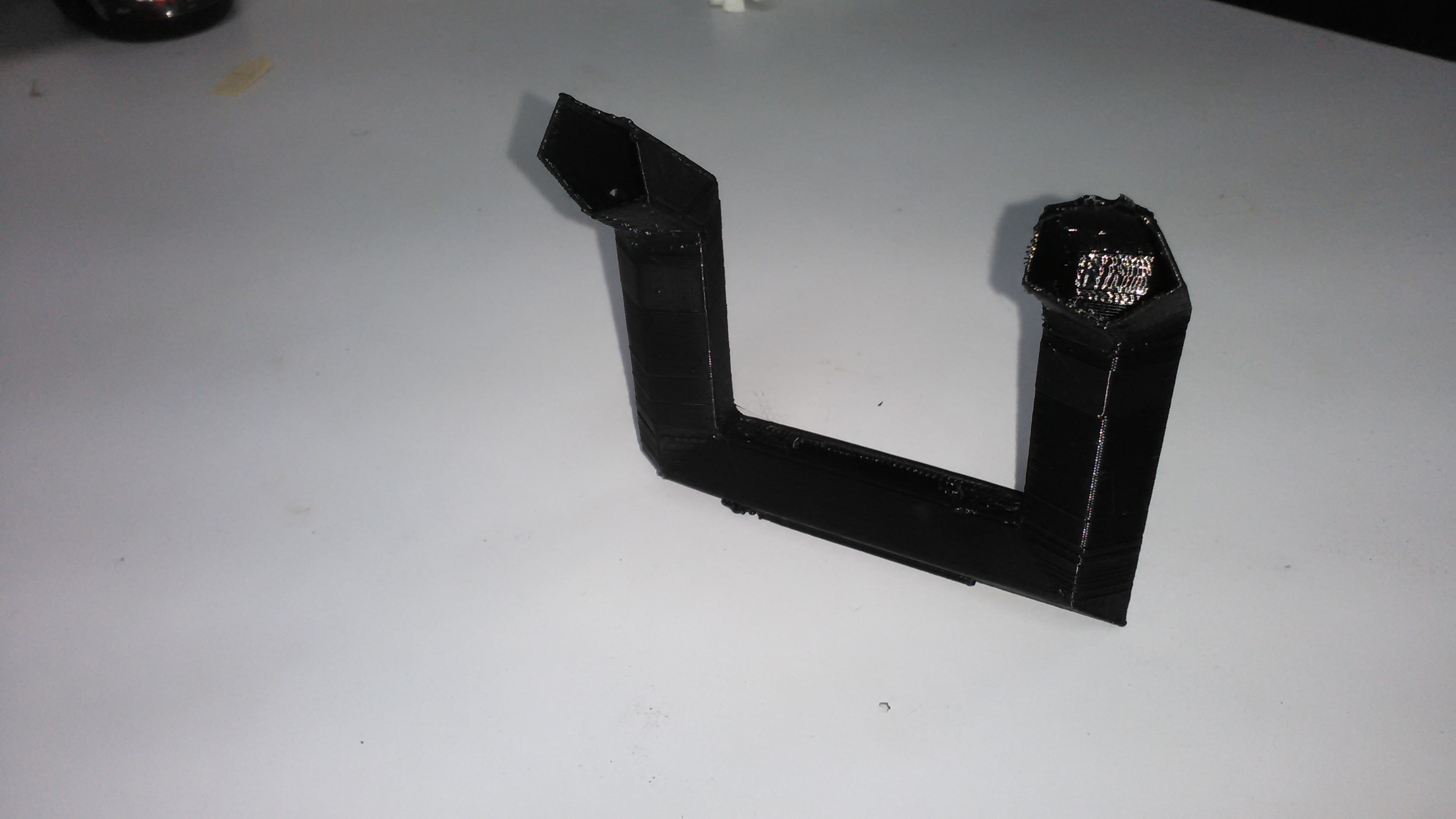
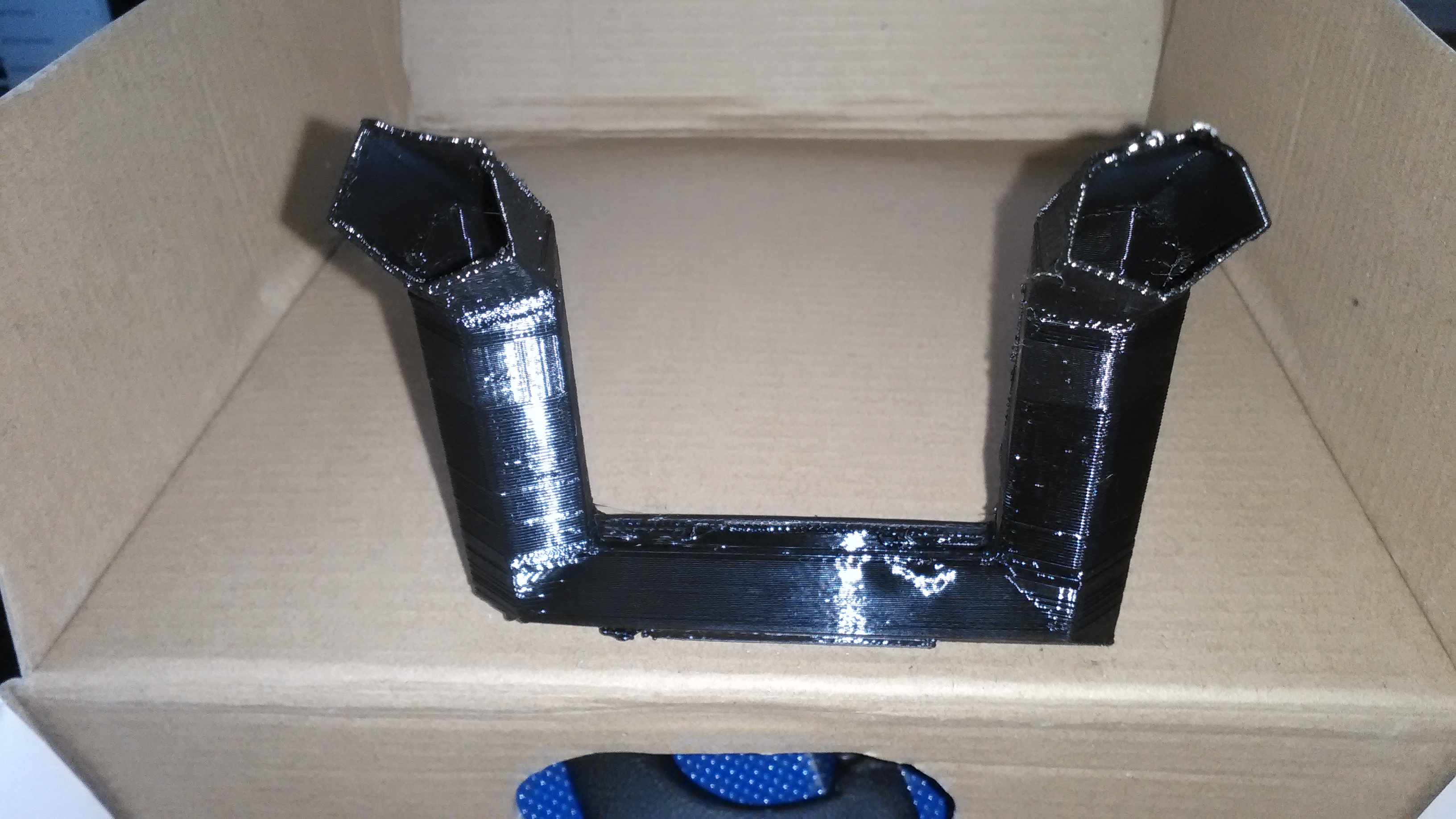
I chose to make the profile of the Amplifier as Pentagon because it can Lay flat on the Printing bed and have angels withing the limit of my printer. a hexagon would exceed that limit.
then i sweept the Pentagon profile along the line. then added a base so it can stand straight.
making a slot for the phone to stand
then i exported it as an STL file so i can print it. Off to the MakerBot now.
the Nozzel was too hot and the printer wasn't retracting the plastic enough so it left a little bit of plasticy hair like thing. the surface could of been alot better. but it was very good for my first print of my OWN desing and i was very happy with it.
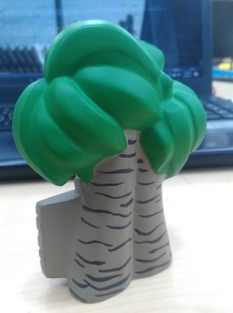
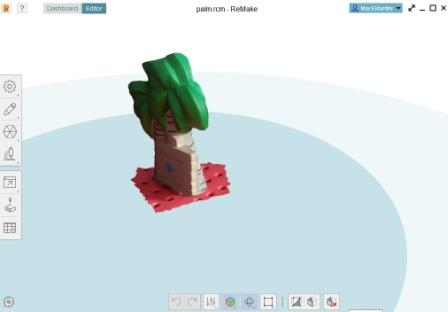
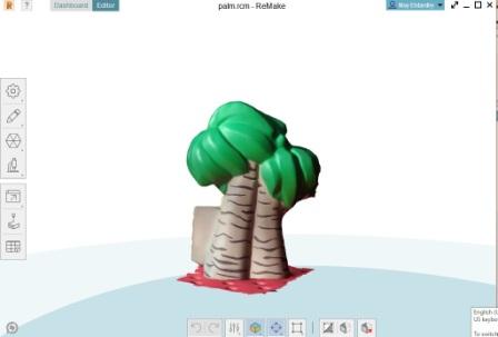
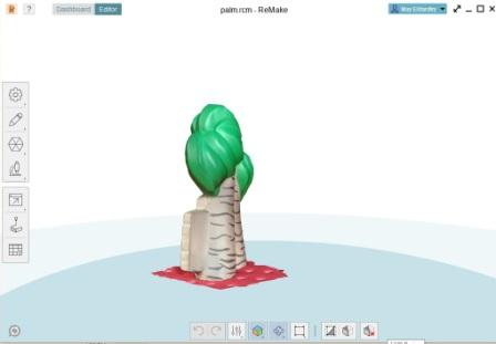
i iused autodesk recap to 3d scan palm tree with my colleague mai el dardery. i used about 55 differrent angles to generate this model
Week 6:Electronics Design
Assignment
Redraw the echo hello-world board, add (at least) a button and LED (with current-limiting resistor), check the design rules, make it
What needs to be done
Shown my process using words/images/screenshots
Explaine problems and how i fixed them, including how i worked with design rules for milling
Include original design files
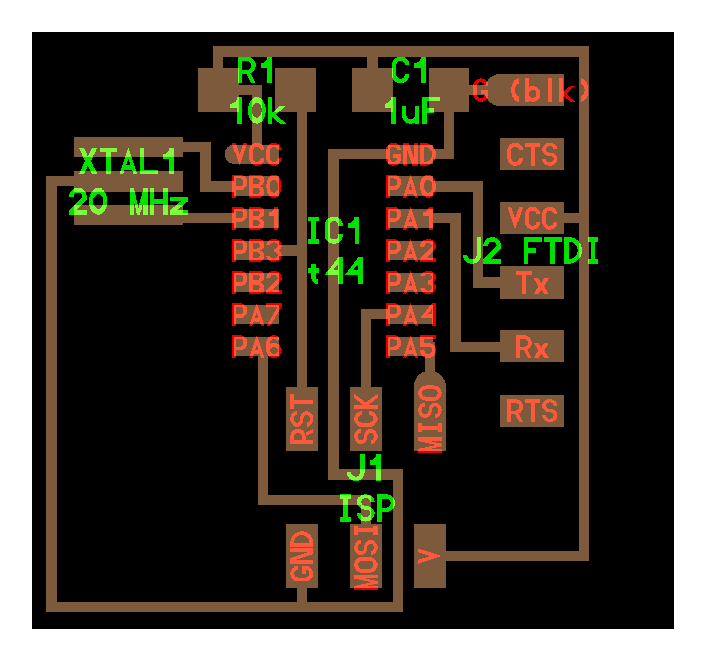
I used Eagle to recreate the Hello-world board and i used Neil's original board "Hello.ftdi.44"
Then i downloaded the Fab Library for Eagle to add more components from it. here is how i added it
first i opened Eagle and from the library menu click on Use.
Then i pick the push button "omron switch", the Current limiting resistor and a LED and add them to the schematic.
Now its time to connect Everything together.
and make the traces and the outline.
then i downloaded the design rule checker file "Fab.dru". and loaded it to the DRC in Eagle.
my board didn't have any errors this time (i'm not always that lucky).
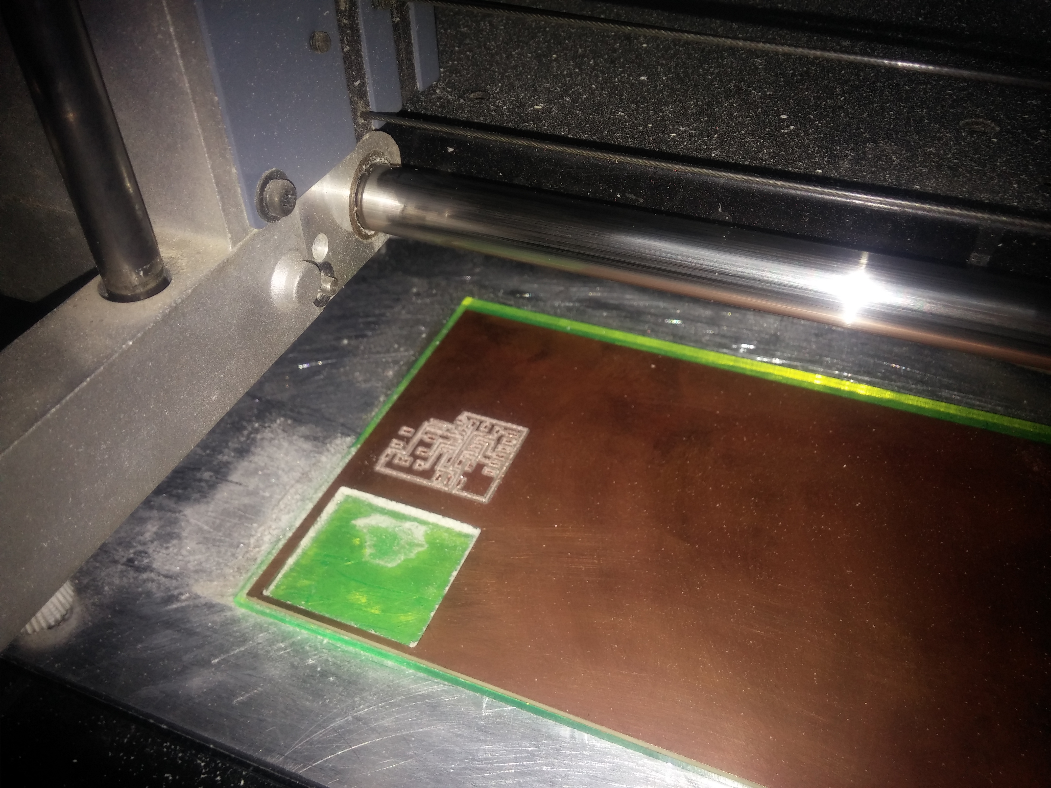
then opened the Fab modules to fabricate the board.
first i chose the input file (PNG).
picking the output file and process.
picking the machine model. and then setting the home position.
finally calculate and send.
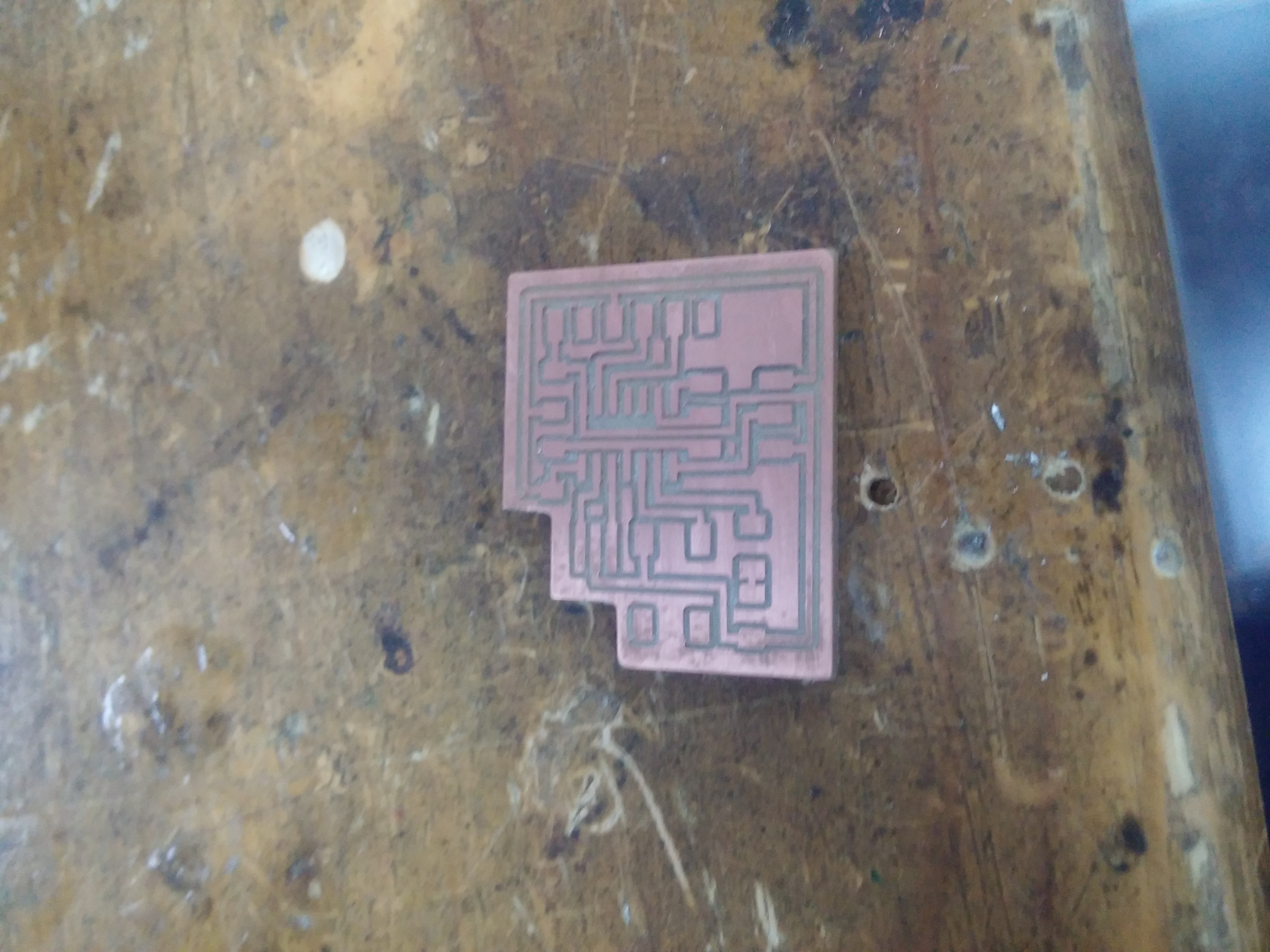
finished fabricating.
after some light finishing and cleaning.
Now its time to solder it.
Weirdly enough i didn't have any problem this week which made me think that something is wrong. other than the machine getting stuck a couple of times i didn't have any problems at all (that was a cable problem).
Included your design files and ‘hero shot’ photos of final object
I started with Fusion because its easy to make G-code with. i wanted to make a Desk with a drawer to use in my final project. i made the design normally as before and after finishing the cad model i went to the CAM environment.
First i opened a new Setup. picked the model orientation and stock point for our machine's configuration.
then i modified the stock dimentions so it can fit the model and added 1mm from the bottom so it can cut through the full thickness of the board.
after the setup is done i choose 2D pockets from the 2D menu. pick the mill bit size and type.
adjust the feedrate (i experimented with 2500, 2000 and 1500) i choose 2000 because it was fast enought, not bad for the mill bit, not too fast for the material. but it was a little bit louder than 1500 which caused touble somtimes because of ear protection and neighbours.
then i choose the areas i want to pocket.
after that i checked the Multiple depth option because it was EXTREMELY loud working without that option. i tried 4mm/pass, 2mm/pass, 1.5mm/pass and 1mm/pass. starting from the 2mm it was good but still a little bit loud. i personally work with 1mm/pass which is a little bit slower bit i feel more comfortable and the finish is better. everyone else uses 1.5mm which works good too.
i switched the Ramp type from Helix to Plunge as the helix was taking too long to clear the pocket.
then i finished the setup and checked the toolpath for anything wrong and simulate it.
then i export the G-code file (.ngc). for our machine we work with EMC2 post configuration. i choose it from the list and typed a special name for my part and pressed "Post".
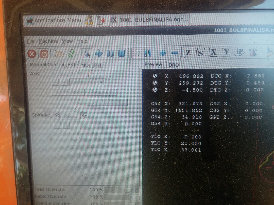
now off to the CNC. first i powered up the machine and opened Linux CNC
then i used the arrow keys to set the Home for the machine (i set the Z way up so i can do an Air cut first).
then pressed "Shift+Home" to home the active axis. repeat for the other 2 axis.
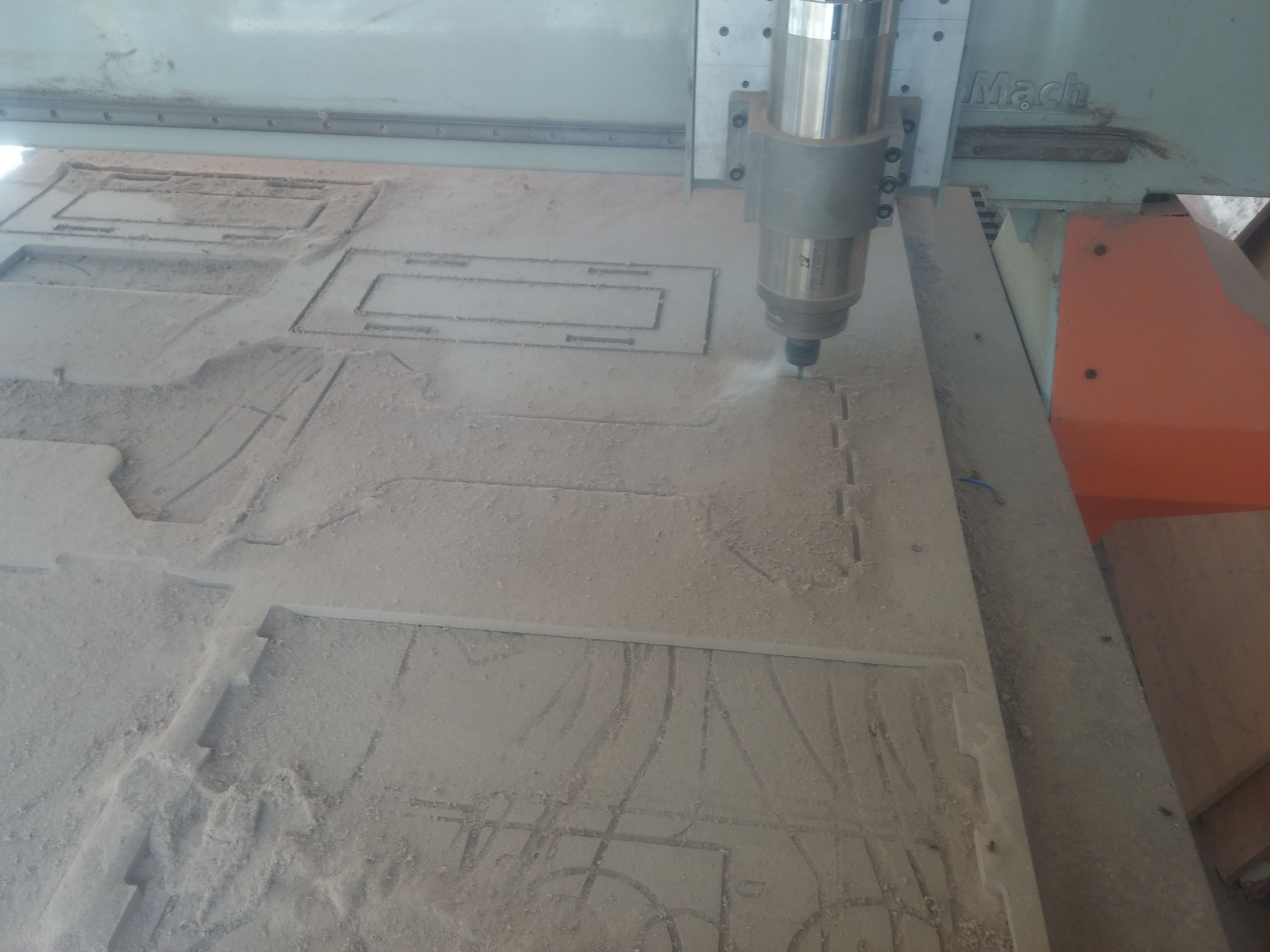
press start for the Air cut and after checking all is safe and the code correct i re-adjust the Z axis to touch the board and start again.
and here is a video of it working.
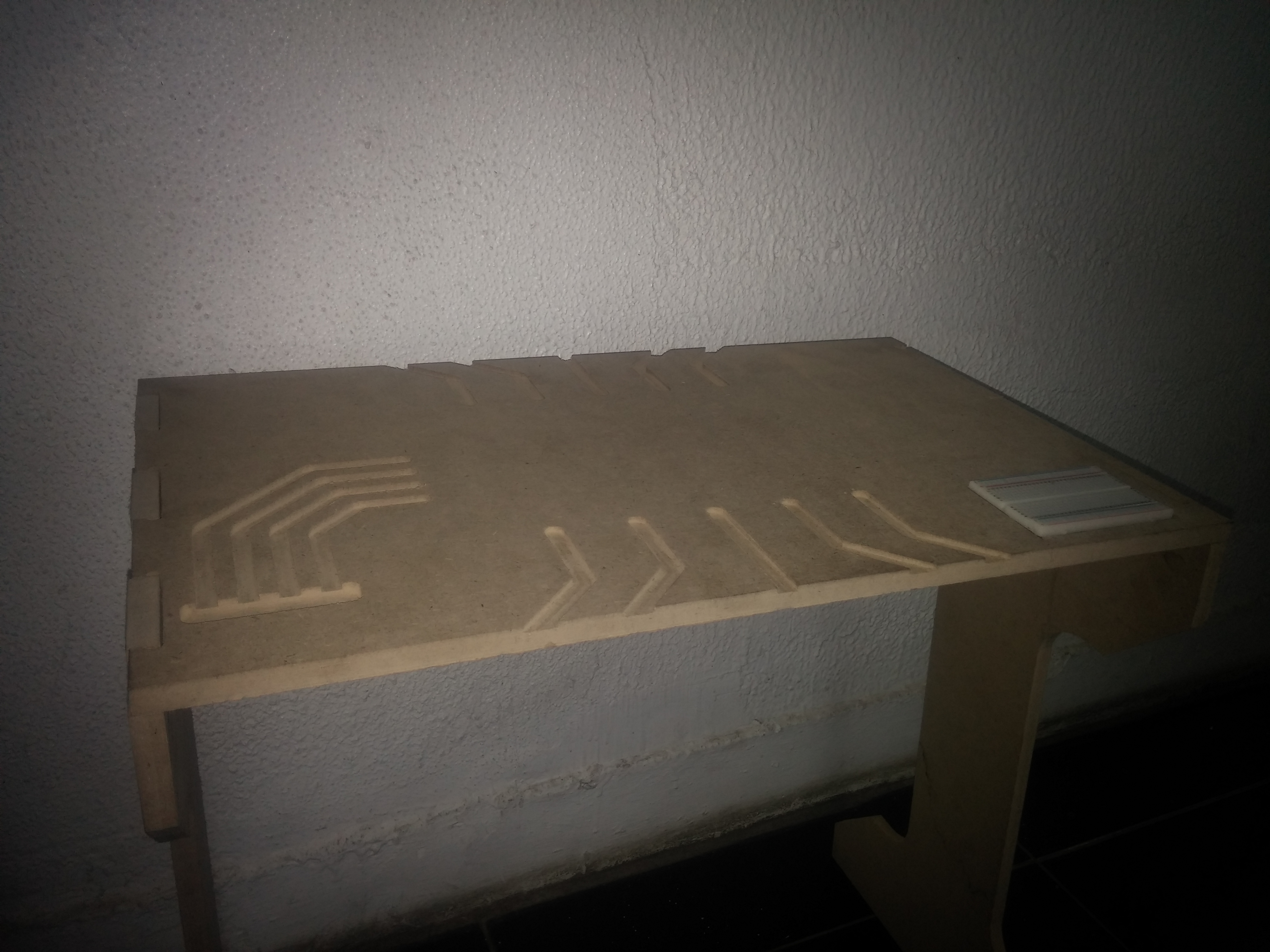
and the finished Object.
Now onto the Problems. i broke 2 Endmills by not checking the Z home and if the spindle is on or off. i tried to do my parts multiple times with differant speeds and feeds with alot of G-code mistakes in the middle which i learned to put my finger on the emergency stop button while starting a new code because of it. and i learned how to remove all home values from the machine which was helpful because i once stopped the machine from the hardware but the software still thinks its operating which led to problems when i tried to operate the machine again. it couldn't know where the Spindle is.
Program my board to do something, with as many different programming languages and programming environments as possible.
What needs to be done
Documented what i learned from reading a microcontroller datasheet
Document questions i have? what i want to learn more about?
Programmed my board
Described the programming process i used
Included my code
The datasheet was very helpful for finding what pins can do what especially with someone who has no experince with microcontrollers like me (only used Arduino All my life)
and also the description of pins was very clear.
But i tried so hard to understand the Architecture of the Attiny so i can better know how it works and how to use it Efficently. but it seemed that the overview was ment for professionals in the feild or i'm just too stupid to understand.
For the code i choose arduino because its the most thing i'm comfortable with and i was tight on time so i couldn't play around alot with C.
my code is very simple. press a button LED does a pattern press it again does another pattern then repeat.
My process for programming is
open the Arduino IDE
Connect the ISP
Choose the type of board i'm programming and the clock speed from tools
Pick the USBTinyISP as a programmer
Upload...
And to the most fun part.. FAILS.
I never knew what is the smoke test. and today i learned xD
i connected the FTDI cable the wrong way and POFFFF smoke everywhere i honstly thought its the laser cutter
second fail is the code.. it took me ALOT of editing for this code to work. i forgot to add digitalRead(pinNumber) for the button so the microcontroller thought its just a normal variable (i think) and it was very unstable reading the push button presses.
Fortunately i got it to work.
Finally i want to ask if the call can give just a tiny bit more about inner workings of a microcontroller for the simple minded or new to the feild like me. and before i started the academy this year i was so eager for this week but it wasn't what i expected (i thought it will talk about low level programming, Hex files, binary and stuff like that but maybe i needed to search a little more) it would be awesome though if this can be added to the academy. although the schadule is very tight and no time for explaination but i think this week is worht explaining. (just my opinion).
Make a Machine and operate it manually, Then Automate it
What needs to be done
Explaine my individual contribution to this project on my own website
we decided to work on A FarmBot that can seed plants and water them. we setup some meeting and devided ourselves into 2 groups. a group for the End Effector and a group for the Axis mechanisim.
i was on the End Effector team and i was responsible for the Pushing mechanisim of the seeds.
we decided on working with a Rack And Pinion Mechanism i made the rack and pinion alongside with the top cover for the cone that will hold the Mechanisim and seeds and the motor.
i had a hard time designing a rack and pinion that will fit together so i searched online for some tools that can help. but it wasn't what i needed. so i had to improvise.
i took a mechanisim that on of my friends made and modified it to fit my need and that's what i came up with.
i've gone through multiple designs for the top cover reaching the one that we finally used which has a Stepper instead of a servo motor and Geshtalt node mounted on the side.
the second version.
the third version.
If you wanna know more about our machine check our
Lab's Page
Week 10: Input Devices
Assignment
Measure something: add a sensor to a microcontroller board that you have designed and read it.
What needs to be done
Describe my design and fabrication process using words/images/screenshots.
Explaine the programming process i used and how the microcontroller datasheet helped.
Explaine problems and how i fixed them
Include original design files and code
I wanted this week's assignment to be on my final project so i designed an input board that acts as a short circuit tester which will be embedded inside the Desk so i can test boards while working on the same desk and don't fill the desk with unnecessary Stuff.
Basically its the same concept as a push button and when you short a pin to the groun (by connecting the 2 leads on a wire like you would with a multimeter) it sends a signal to another board that has a buzzer in it and makes a buzzing sound.
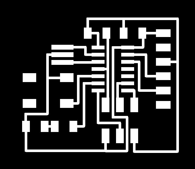
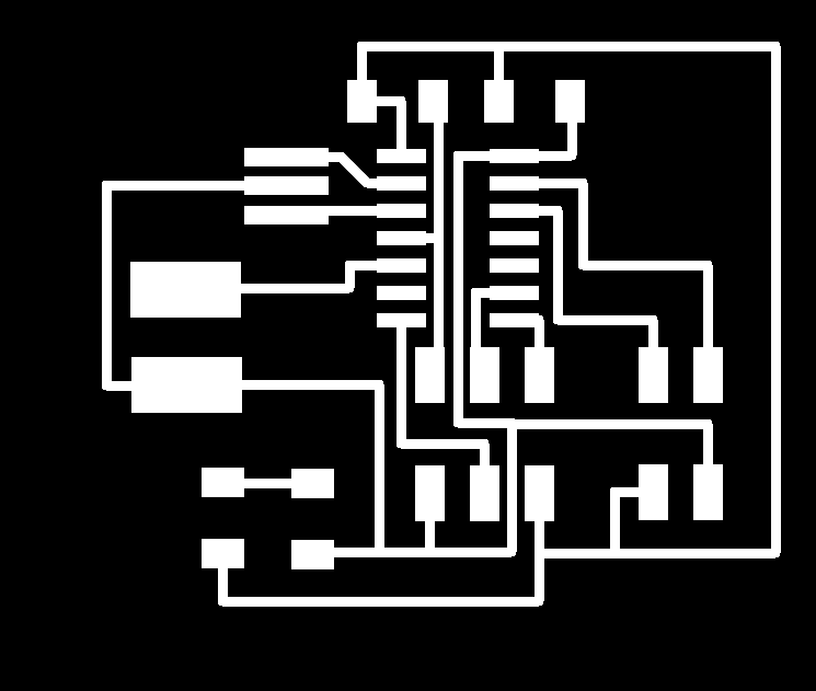
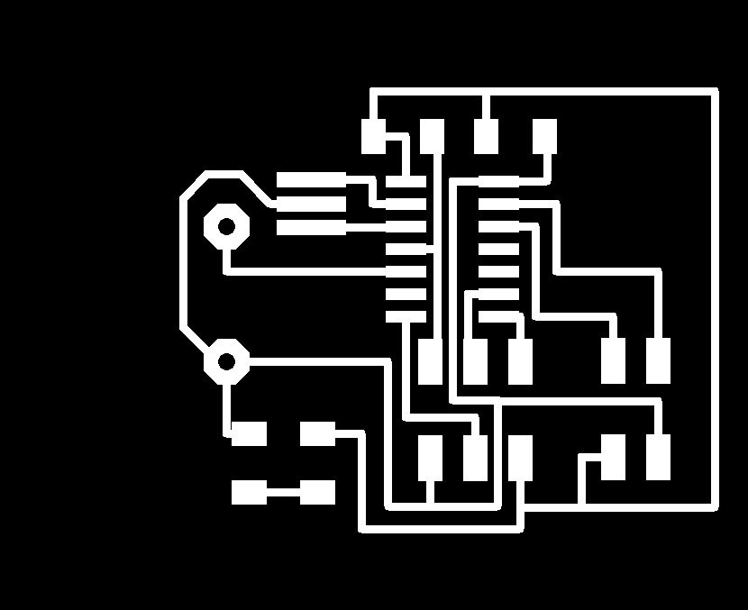
Schematic
Board
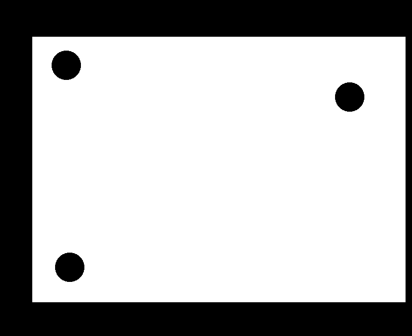
Traces and Outline
I used Eagle to design my Board as i was very familiar with its environment so i did the schematics and laid out the board then connected the traces. after that i hide all the layers expet the top layer and exported as a monochrome PNG. i did the same with the dimensions Layer.
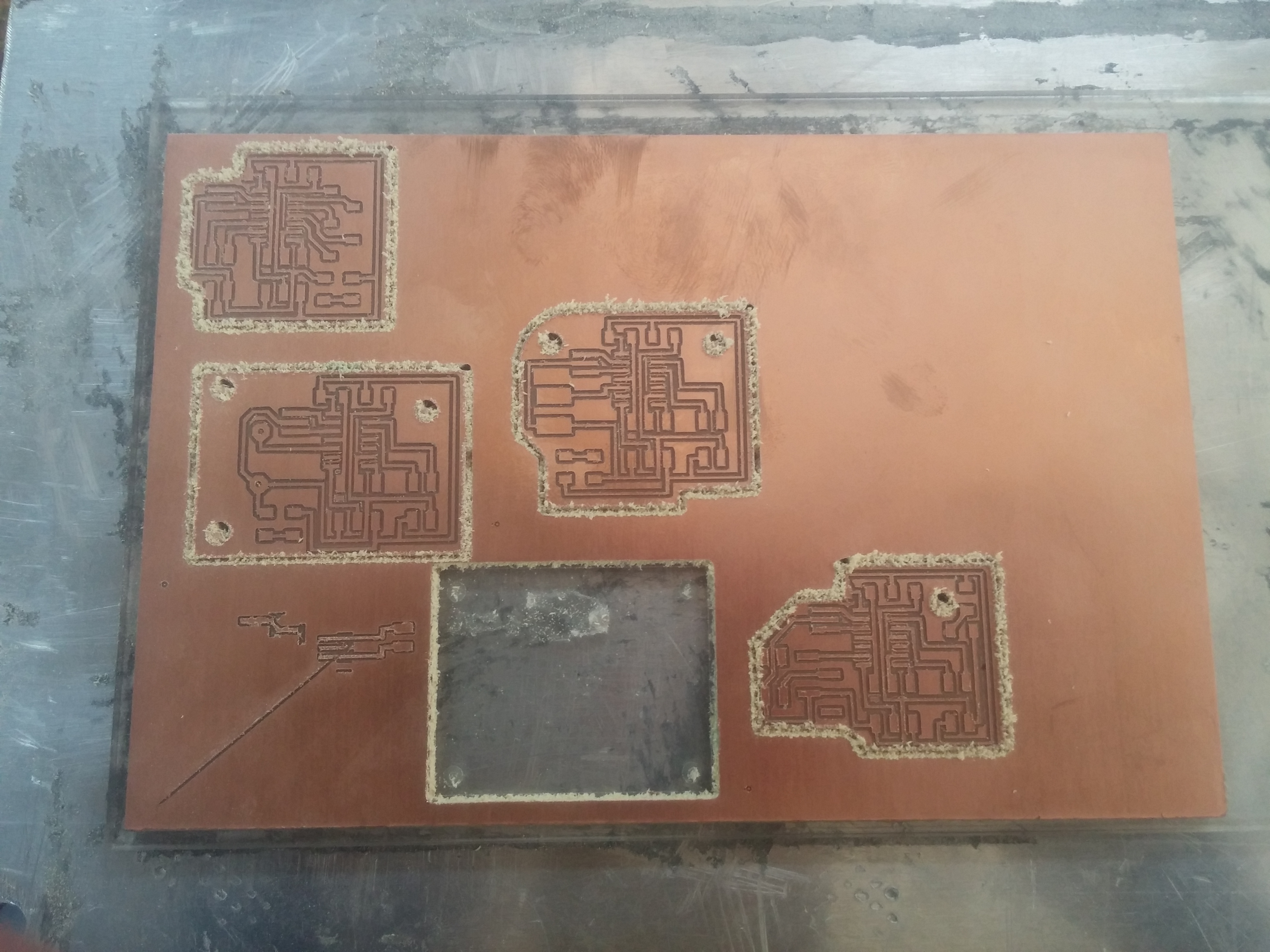
i milled the board with our MDX-20 using Fab Modules.
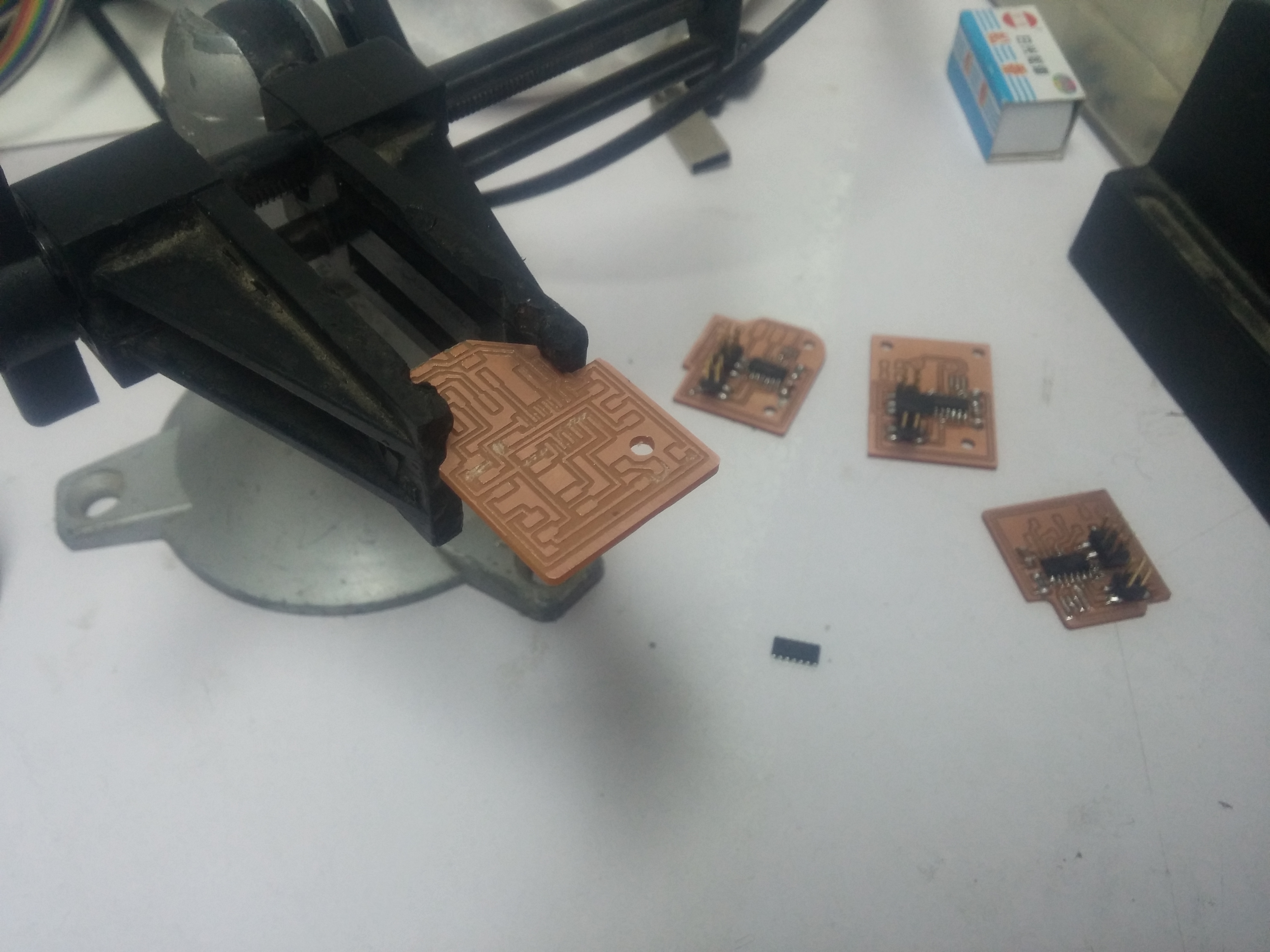
Then soldering which i started to get used to after my 14th time soldering and failing. (i was doing all the final project boards together which are 2 Input and 2 Output boards that all communicate together).
then i uploaded the Code using the TinyISP and the board didn't work because i set the wrong crystal value (20 instead of the internal 8)
i re-milled the board because i couldn't desolider the Attiny and uploaded the code again (with the correct crystal this time) and it still didn't work. the value was unconsistant and everytime i pull down the button it does everything in the setup and continues the code.
after debugging and searching online for a while that happened because the ground wasn't connected (i think) so when i touch the gound trace it closes the loop and powers up the Atting and start the code from the Setup and when i remoce the wire that is shorting the button the Attiny Loses power again. So i went ahead and soldered that ground pin and checked that there are no other shorts and everything is connected. and it worked perfectly.(i have no photos of the debugging process because i was so frustraited and wasn't in the mood of "yeah i should document this").
and yes. the datasheet was VERY helpful figuring that error because i didn't know what reset does and that i can power the ATtiny without connecting the GND pin.
but here is a video of the board after alot of debugging
Add an output device to a microcontroller board you've designed and program it to do something
What needs to be done
Described your design and fabrication process using words/images/screenshots.
Explained the programming process/es you used and how the microcontroller datasheet helped you.
Outlined problems and how you fixed them
Included original design files and code
for this week i reused my Input Devices board to communicate with this Output board which is a buzzer that is triggered when a short is happeneing in the Input Circut.
The schematic and board were fairly easy because i made alot of mistakes in previous boards that made me fimiliar with what mistakes to avoid and what thing i should try because they might be a better solution.
the code
This board didn't have alot of problems becuase i tryied to avoid them as much as possiable from the last board i made in input devices so it went pretty smooth. and here is a video of it working.
Design and make a 3D mould (~ft2 /30x30cm), and produce a fibre composite part in it
What needs to be done
Shown how you made your mould and created the composite
Described problems and how you fixed them
Included your design files and ‘hero shot’ photos of the mould and the final part
Read and linked to the material safety data sheet (MSDS) and technical data sheet (TDS) for the resins that you're using
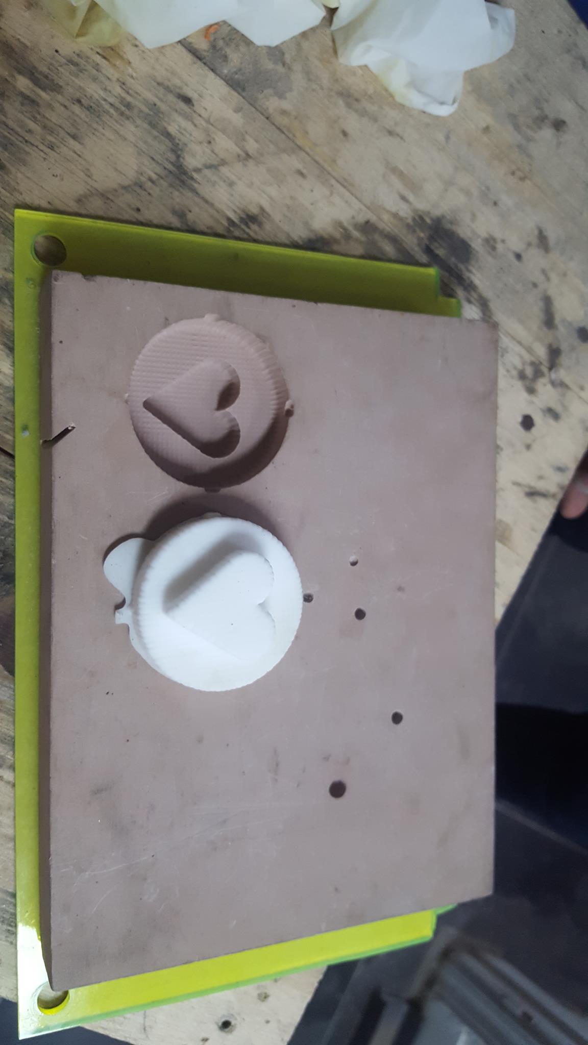
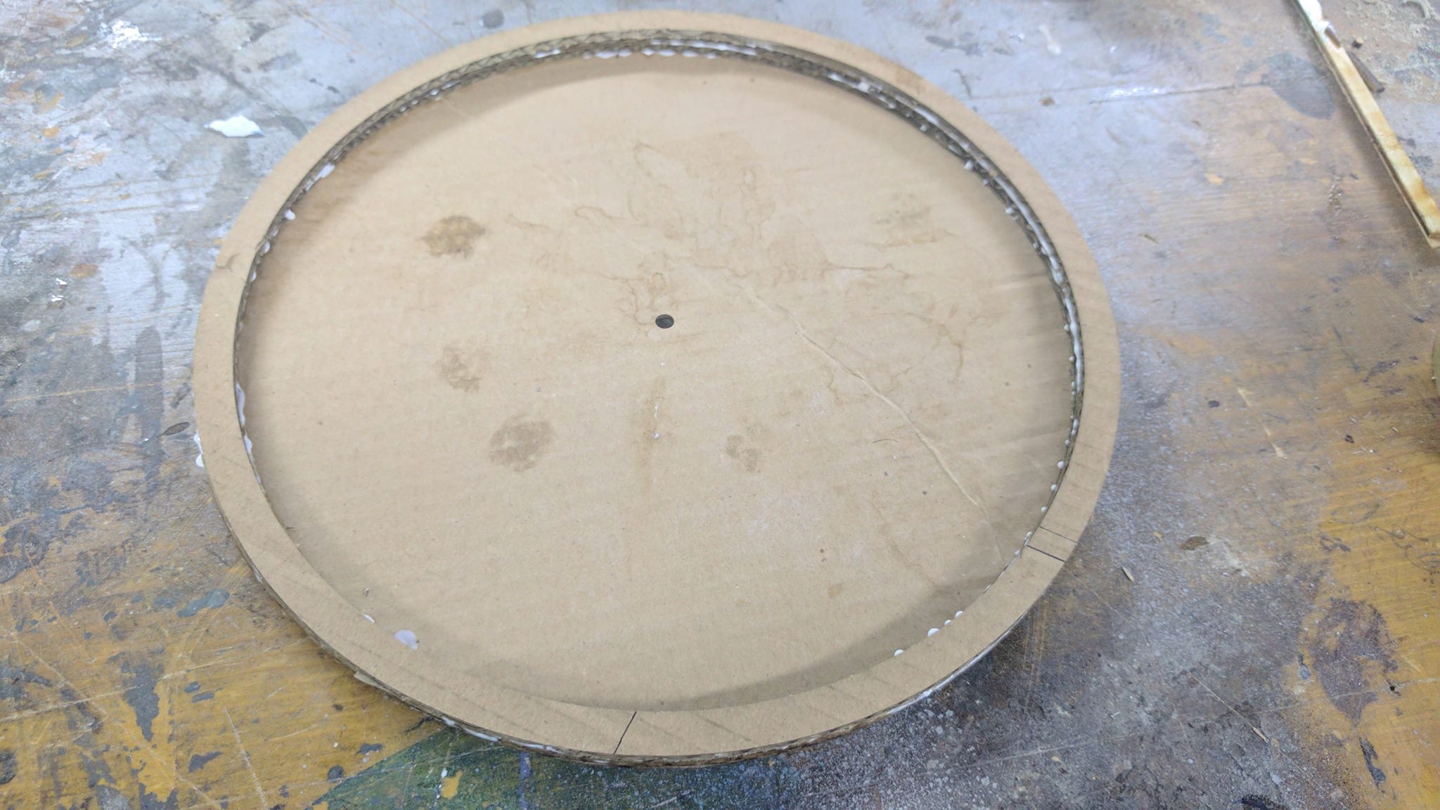
i wanted to make a Cover for a wooden clock that i made so i made a mould with the desired shape on fusion and saved its profiles as DXF and laser cut them out of Cardboard.
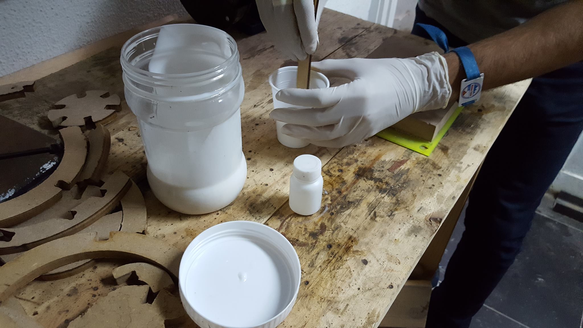
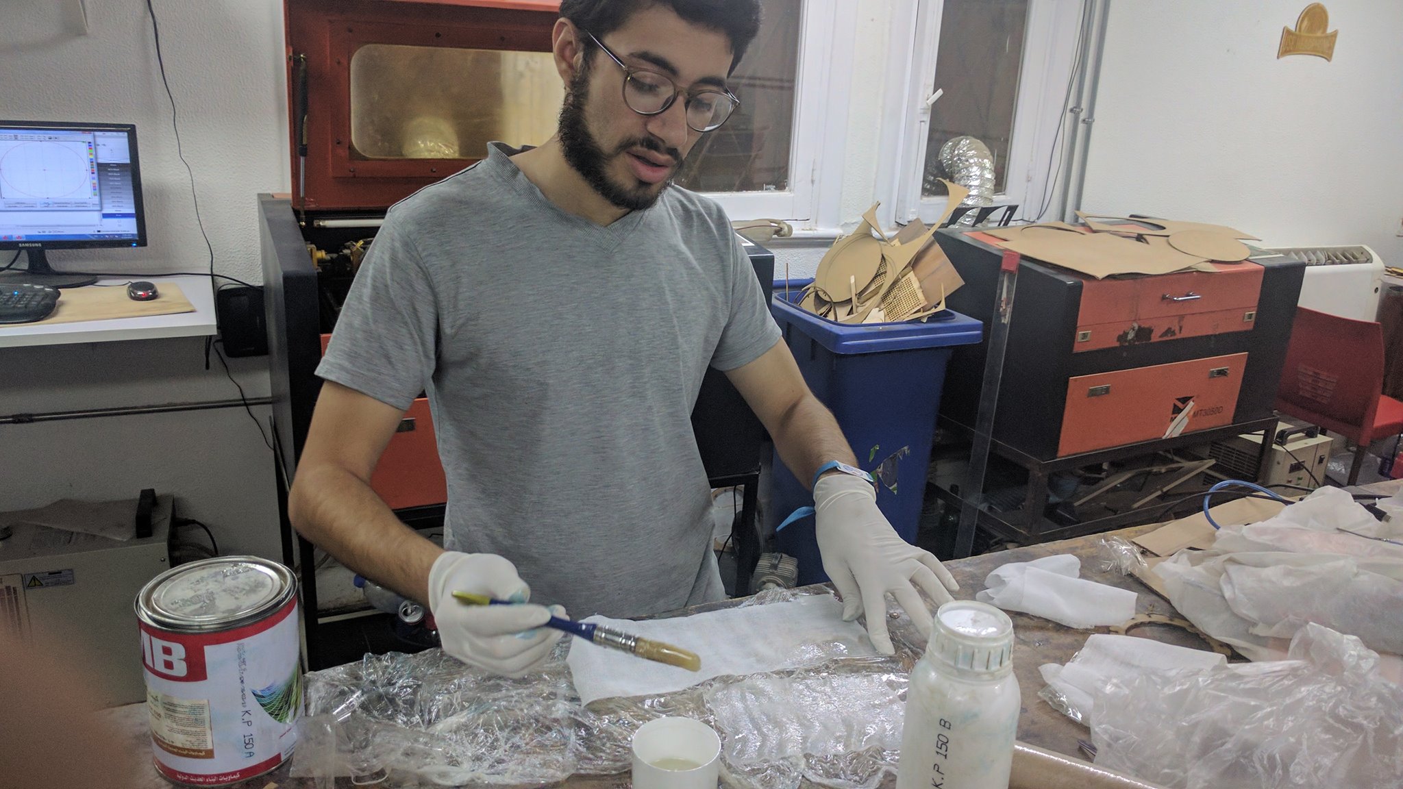
then i mixed 2A:1B mixture of Epoxy and kept mixing for 1 min. then i started laying up the fabric and wetting it with Epoxy.
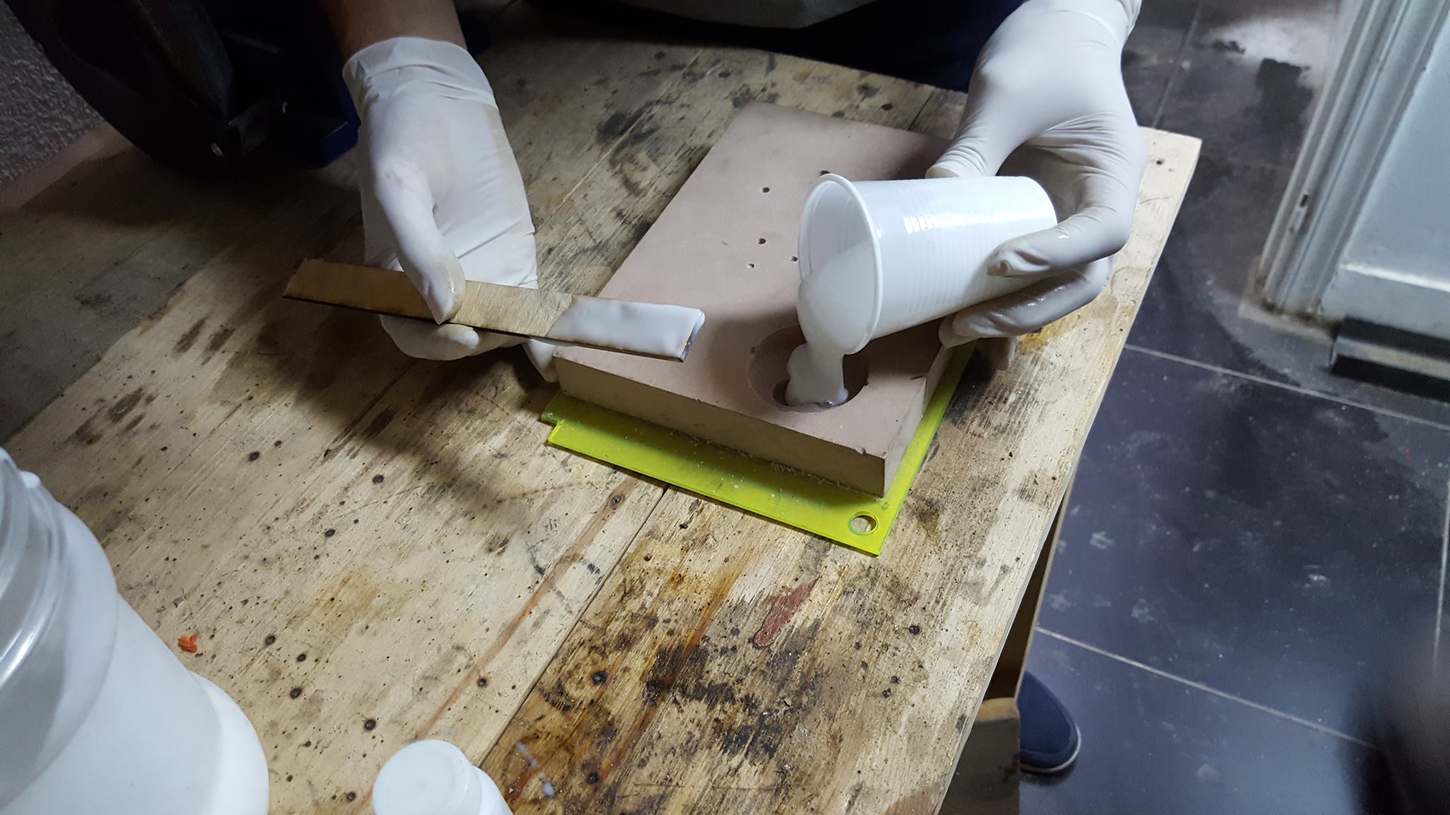
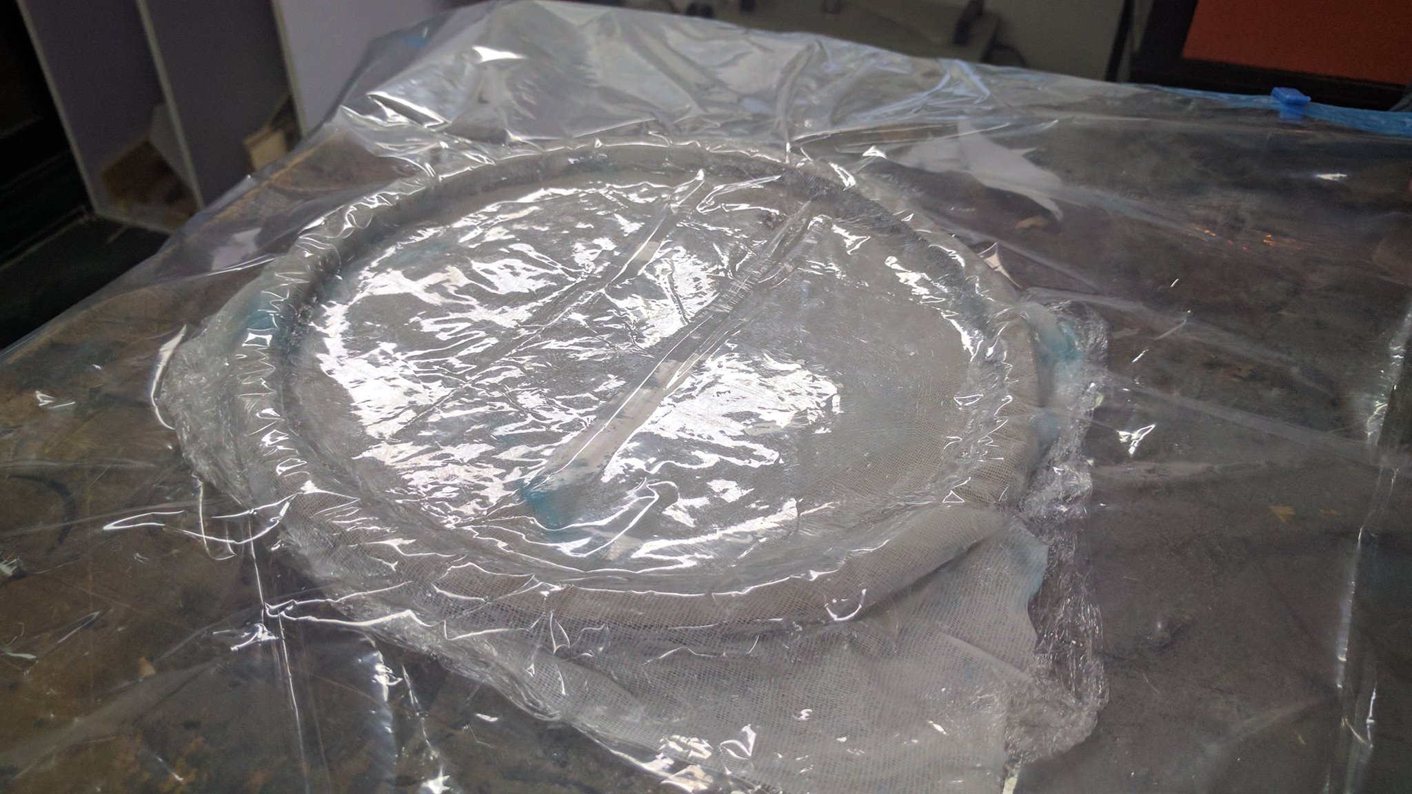
then i layed the fabric on the mould and pressed it tight and repeated for 2 more layers. then put it into the vacuum bag.
waited for the next day to cure and its done.
Week 14: Embedded Networking and Communication
Assignment
Design and build a wired &/or wireless network connecting at least two processors
What needs to be done
Described your design and fabrication process using words/images/screenshots
Explained the programming process/es you used.
Outlined problems and how you fixed them
Included original design files and code
for this week i connected the input and output board to act as a short Circuit tester that are communicating through a Serial TX/RX bus with input board sending charachters to the output and it acts upon the data recesved. you can find both of the board in my 10th and 12th assignments Here.
i explained how the boards are made and what is the pourpouse of each board in the input and output weeks.
and here is a video of them communicating.
Week 15: Interface and Application Programming
Assignment
Write an application that interfaces with an input and/or output device that you made, comparing as many tool options as possible.
What needs to be done
Described your process using words/images/screenshots
Explained the the GUI that you made and how you did it
Outlined problems and how you fixed them
Included original code
for this week i made a mobile app to interface with my Output Devices board. i used a blutooth module HC-06 to interface my phone and the board i made in the Output devices to act as an Alarm when i press on a button in my phone.
My GUI is made out of 2 buttons one starts the Alarm and Another stops it, it is very simple to do.
I Made the interface with MIT app inventor and followed this Tutorial its very simple to do just following there steps.
My Project is a Desk that makes my life easier when working on a project.
What will it do?
what i have in mind is:
1) power supply with multiple channels for fast prototyping.
2) a Short circuit Tester.
3) and a simple Security system for little devils like my sister's little daughter.
Who's done what beforehand?
There is OpenDesk who make Open Source furnature designs but none of them make it customuziable for makers.
There is also alot of Desks makers and wood worker on Youtube who make Customuzable Desks for everything from Engineers to Gamers to makers.
What materials and components will be required? From where? How much will it cost?
200cm*120cm*11mm MDF boards - Local Vendor - 300LE
Nails x30 - Local Vendor - 20LE
Paint x2 - Local Vendor - 60LE
Tester Board - Made by me - 90LE
Buzzer Board - Made By me - 77LE
What parts and systems will be made?
1-The desk it self will be routed out of 11mm thick MDF.
2-The servo motor lock mechanism will be 3D printed.
3-The Short Circuit tester board and buzzer board.
4-The NumPad board for typing the password for the lock.
what processes will be used?
1.CAD design for desk parts.
2.gCode for CNC router machining MDF.
3.3D printing.
4.Eagle for Designing PCBs.
5.PCB manufacturing.
What questions need to be answered?
what features will be needed and what will be Too much to add?
is it better to use press fit joints or using wood nails?
testing with various kinds of wood.
What is the schedule?
i already finished most of the project in previous assignments so my plans for future development is to add the security system and adding a variable power supply embedded in the desk for fast testing and prototyping.
How it will be evaluated?
On the integration of learned skills through out the academy and being easy for anyone to make in any fab lab and on its modularity.
Week 17: Invention, Intellectual property and Business models
For this week its required to pick a license or a copy right to share the Final project under its terms.
for me its both a business and a project that i want the whole community to be able to make and share it.
So i decided to leave under the Creative Commons Attribution-NonCommercial Share Alike 4.0 International License.
which lets the community Make, Edit and Tweak whatever they want, At the same time i can commercialize it for those who can't make it or don't have access to a fablab


.png)
.png)
.png)
.png)
.png)
.jpg)
.jpg)
.png)
.png)
.png)
.png)
.png)
.png)
.png)
.png)
.png)
.png)
.png)
.png)
.png)
.png)

.png)
.png)
.png)
.png)
.png)
.png)
.png)
.png)
.png)

.png)
.png)
.png)
.png)
.png)
.png)
.png)
.png)
.png)
.png)
.png)
.png)
.png)
.png)
.png)
.png)
.png)
.png)
.png)
.png)
.png)
.png)
.png)
.png)
.png)
.png)
.png)
.png)
.png)
.png)
.png) and also the description of pins was very clear.
and also the description of pins was very clear.
.png) But i tried so hard to understand the Architecture of the Attiny so i can better know how it works and how to use it Efficently. but it seemed that the overview was ment for professionals in the feild or i'm just too stupid to understand.
But i tried so hard to understand the Architecture of the Attiny so i can better know how it works and how to use it Efficently. but it seemed that the overview was ment for professionals in the feild or i'm just too stupid to understand.
.png)
.png)
.png)
.png)
.png)
.png)
.png)
.png)
.png)
.png)

.png)
.png)


.png)
.png)
.png)