Week 6 - Electronics Design
In this week I will recreate a circuit-board and attch a LED and a current limiting resitor to it. When finished, I will mill it and solder all components on it. The milling process with the Roland SRM-20 I have figured out in the assignement of week 4 when I milled the ISP board.
Redraw the echo hello world board
To my extend the most common used program for drawing circuit borad is Eagle. Just download the installer and install.The necessary information to draw the echo hello world board are gathered on the class page under this link. There is a good description on how to aproach this task and working with Eagle. It is found in the tutorials of the Fab Academy. It describe a previous version of Eagle, before it was merged into the Autodesk suite but it is very helpful though. The link to the schematic does not exist anymore, too dbad that means, I have to redraw the whole board myself. I strat a new project hello echo world.
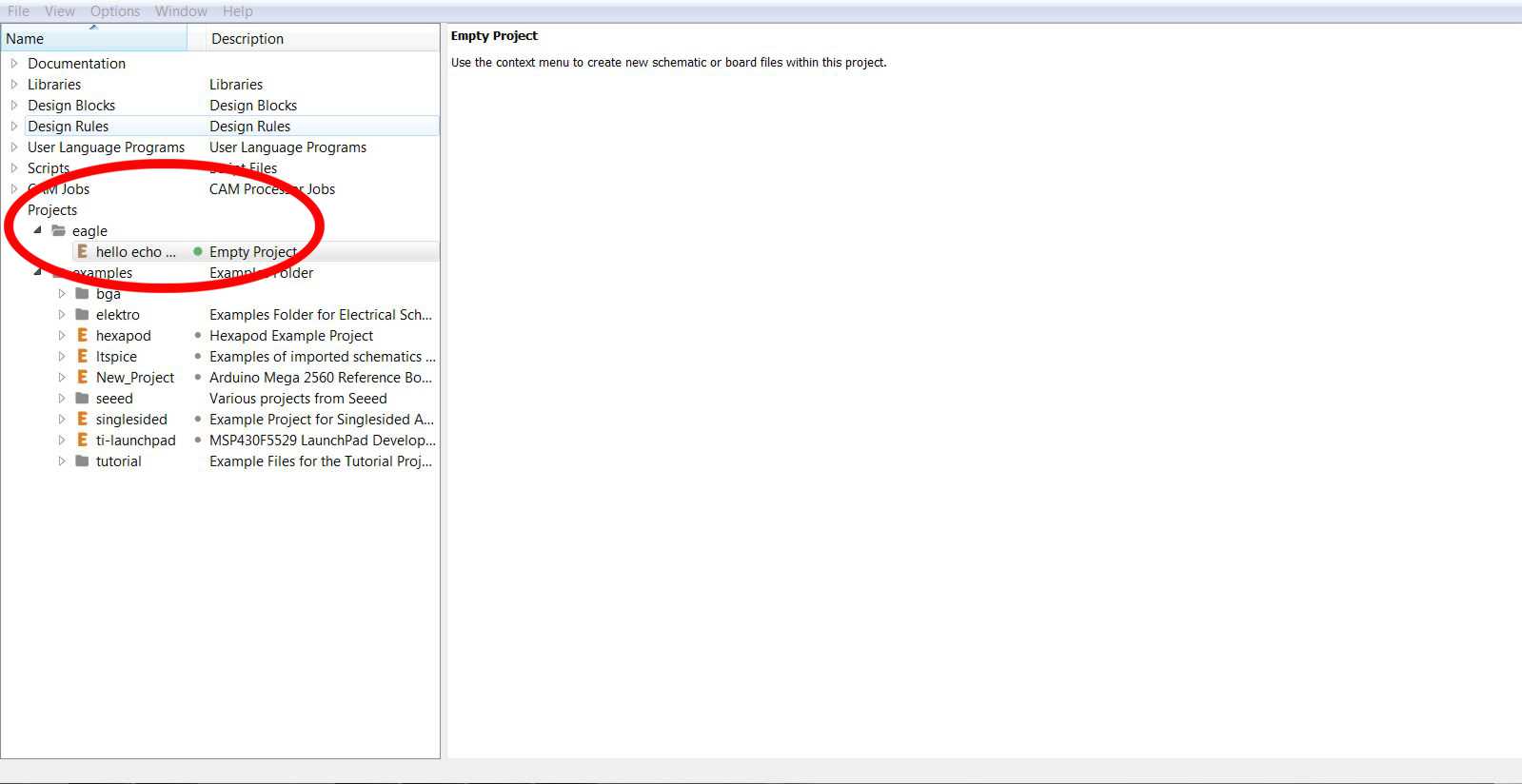
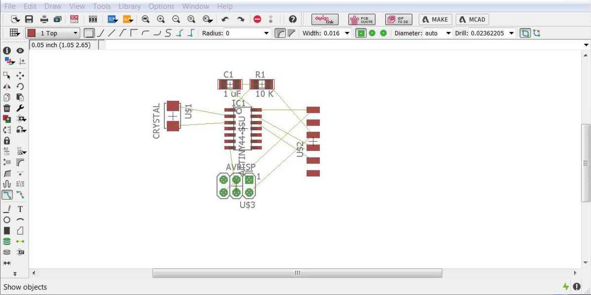
There are two files, which needs to be created in Eagle, to manufacture a circuit board. First, the schematic (.sch), where one put together all the components and connect them. Out of that, one creates the board (.brd), the layout, which is then actually milled.
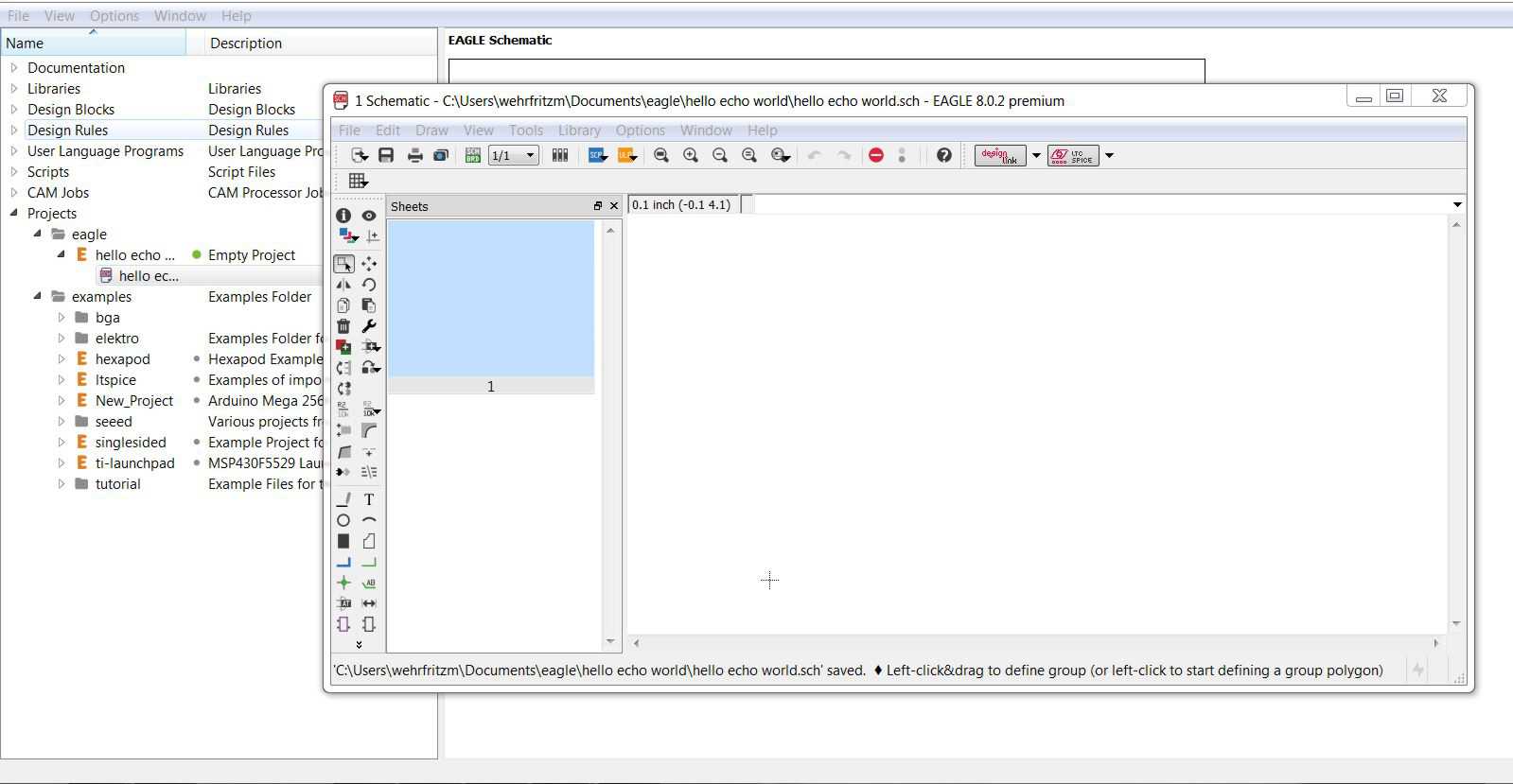
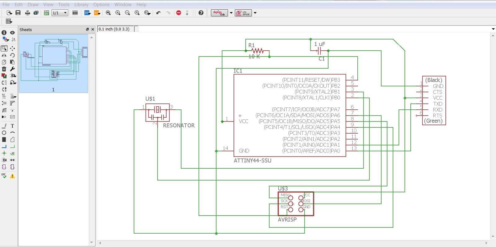
Let's start with the schematic. Open a new schematic with right click on the project and a new window pops out.
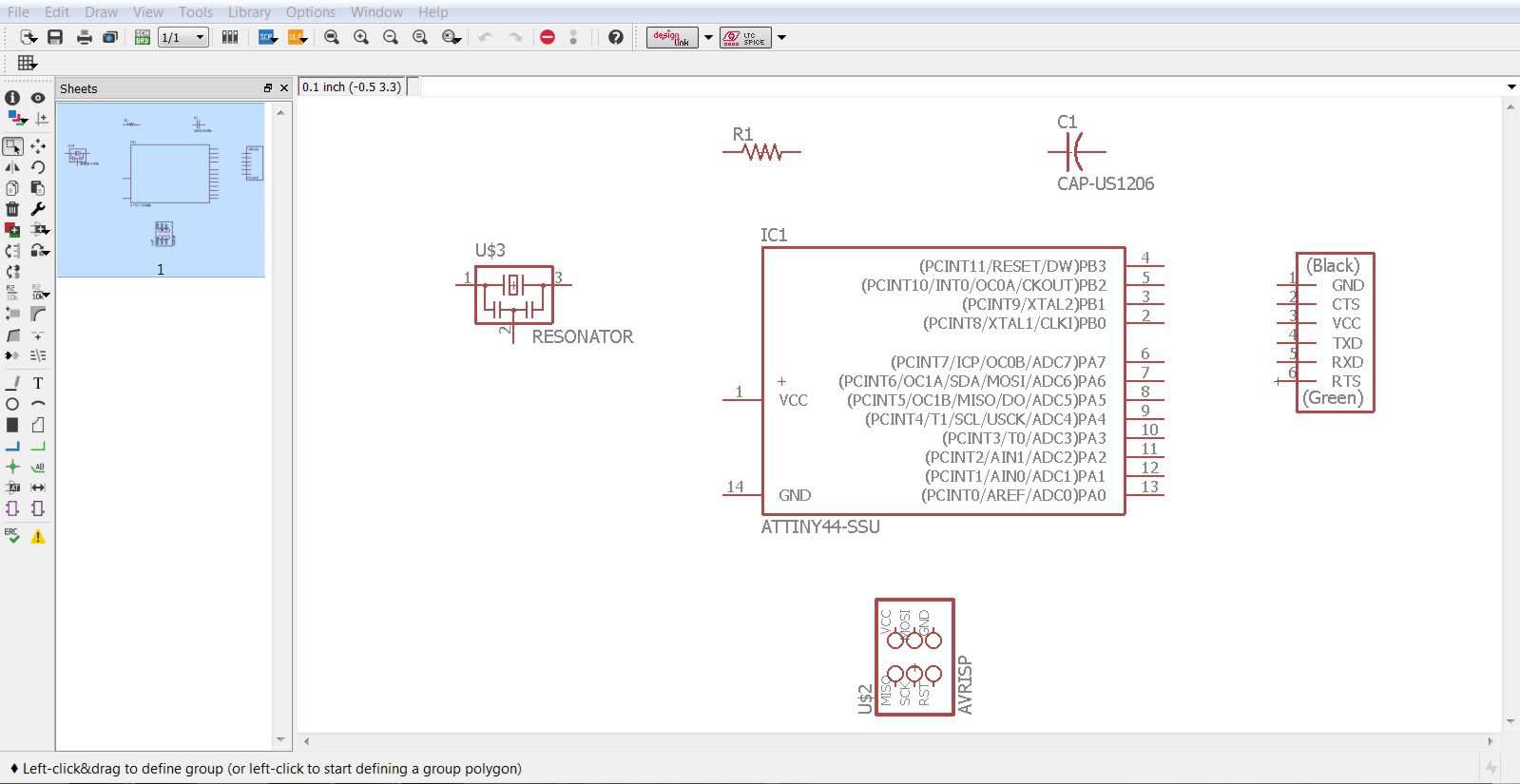
Since I already know the parts, which are on the board, from the link, I just need to find them in the libray and add them on the board.
- 6-pin programming header: for programming the board
- microcontroller: attiny44A, the 'brain' of the board
- FTDI header: powers the board and allows board to talk to computer
- 20MHz resonator: external clock, the internal IC clock is not 100% exact
- Resistor 10 kΩ: limits current
- Capacitor 1 µF: stores charges
There is also a certain library provided, for the specific use during the Fab Academy. These needs to be copied in the lbr folder in the Eagle directory. Just select then the fab.lbr in the Library when starting Eagle and all necessary componets are available.
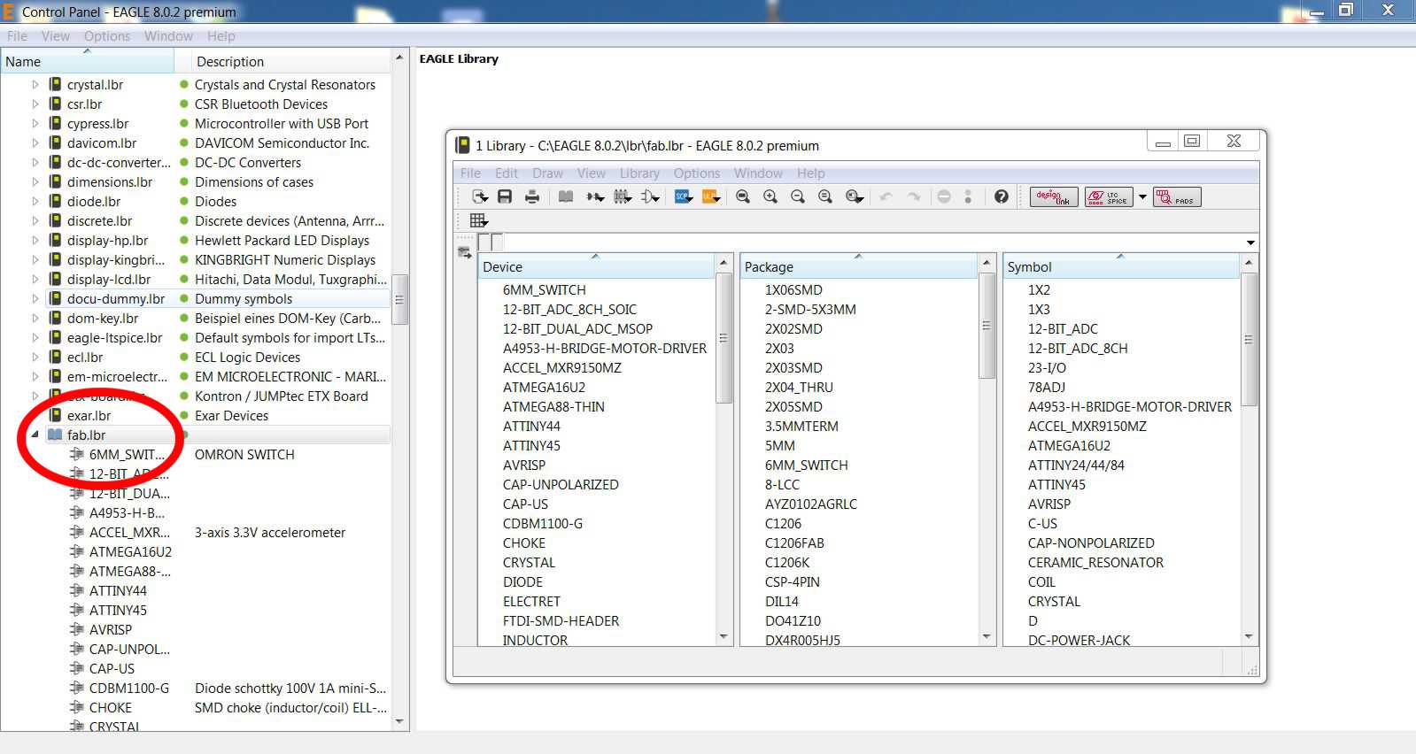
To add a component, just type add in the command line or go to Edit/Add. Then choose the library, you (in my case it is fab) and browse for the part. The SMD-parts (surface mounted devices) have the imperial size 1206. After collecting all parts together, I need to connect them according to the description of the hello echo world board. First I change the values sof the resistor and capacitor to the right 10 kΩ and 1 µF by typing value in the command line and clicking on the part before I change the number. The same is for name and label.
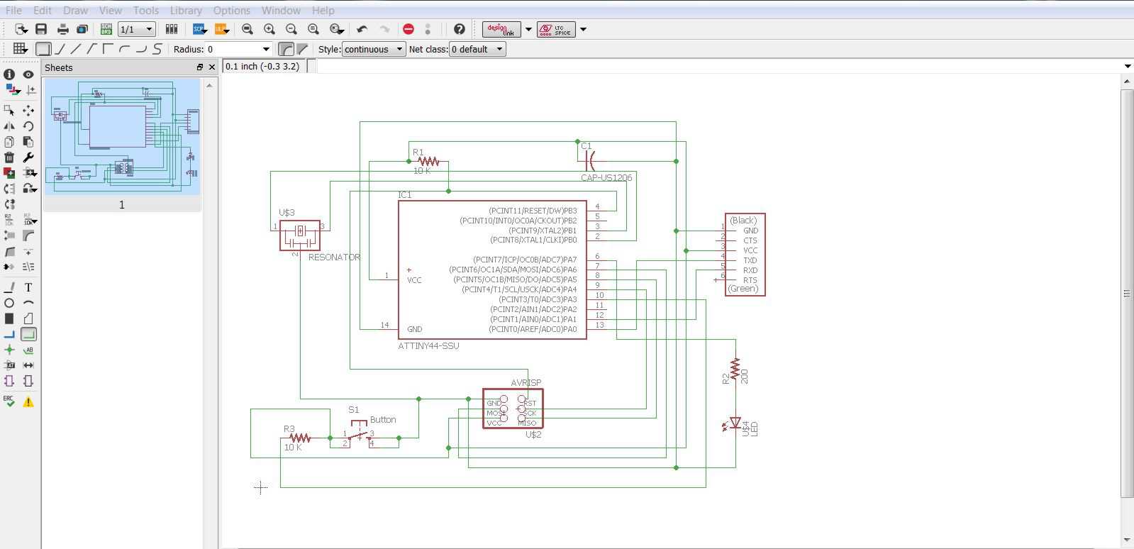
The next step is to add a switch and a LED with the proper current limiting resistor to the circuit.
- push button: switches on and off
- Resistor 10 kΩ: limits current
- Capacitor 1 µF: stores charges
Following several descriptions from this assignement, I am using a 10 kΩ resistor at the push button and I will connect the LED to PA 7 of the ATTiny44 and the button to PA 3 and via the 10 kΩ to the supply voltage. Since all PA pins are 8 bit bi-directionalinput/output pins. This gives me two options to control the LED: first direct over PA 3 and second indirect over the button and PA 7. I can program the ATTiny44 to respond to the button and change the signal on PA 3.
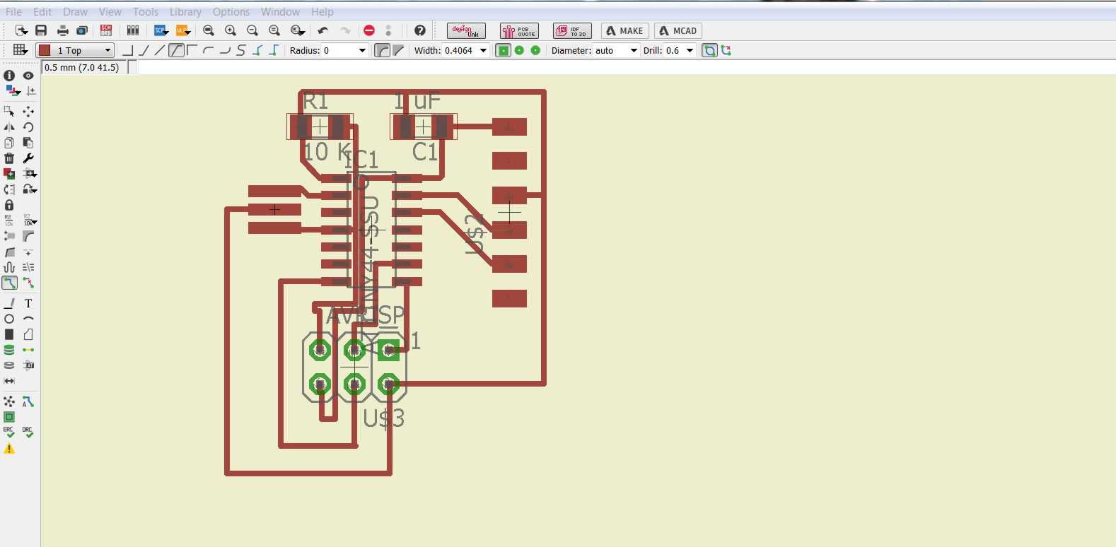
I also changed the grid to finest, as I wired under the ATTiny. In the first board are those wires pretty close and the mill wont be ab le to cut this. Another thing is the footprint of the ISP. I need to use the SMD version, since the IC version shows no pads.
To be sure that the board works I need to perform an ERC = electronic rules check in the schematics. This test checks if there are some connection issues. In the board mode, I need to do a DRC = Design rules check. With this, I make sure, that the distances between the routes are reasonable large, that the mill can cut them and that there is no influence (induction or magnetic). The default setting is 16 mil, which is the diameter of the 1/64 bit. All results were no errors, so I can mill it.
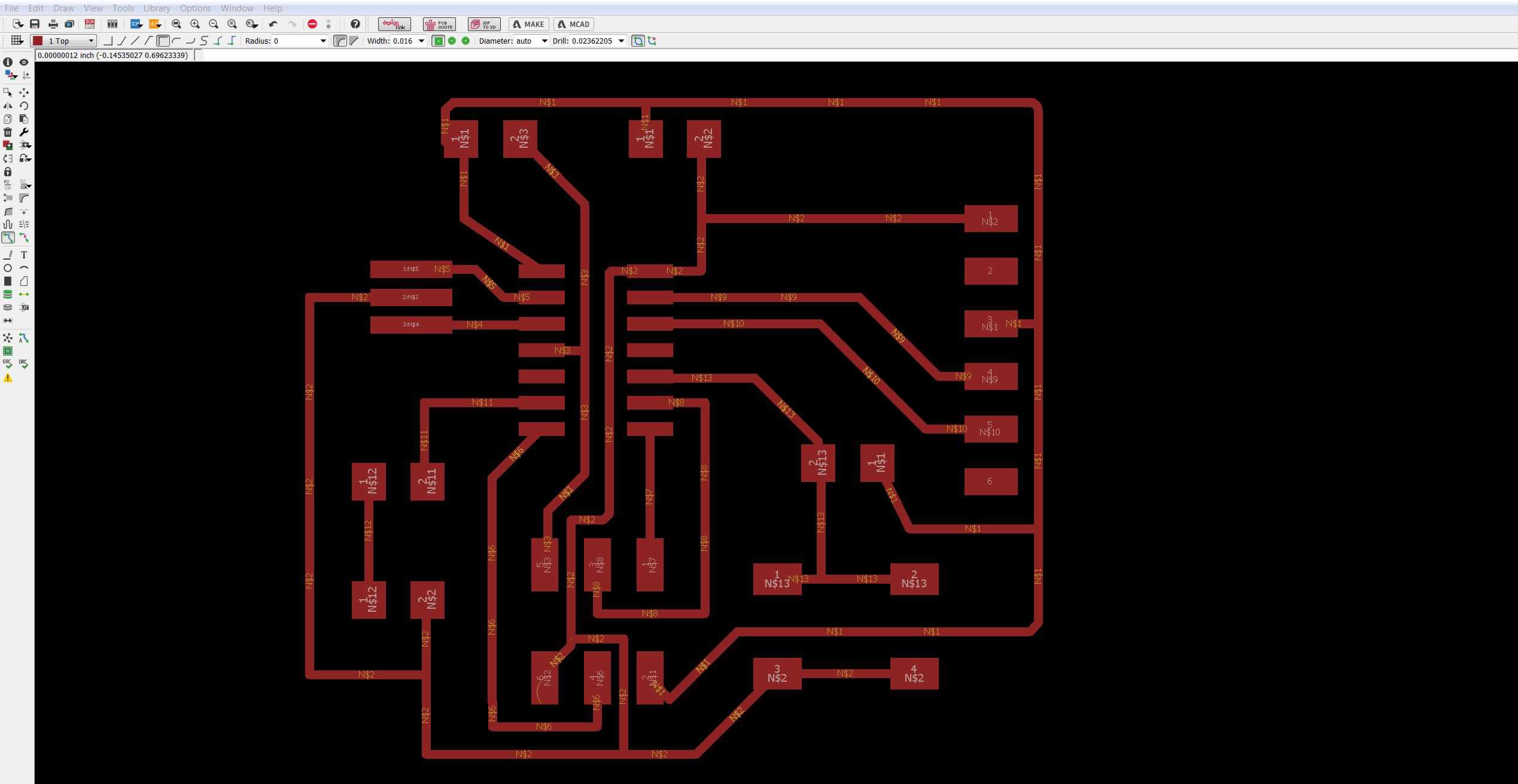
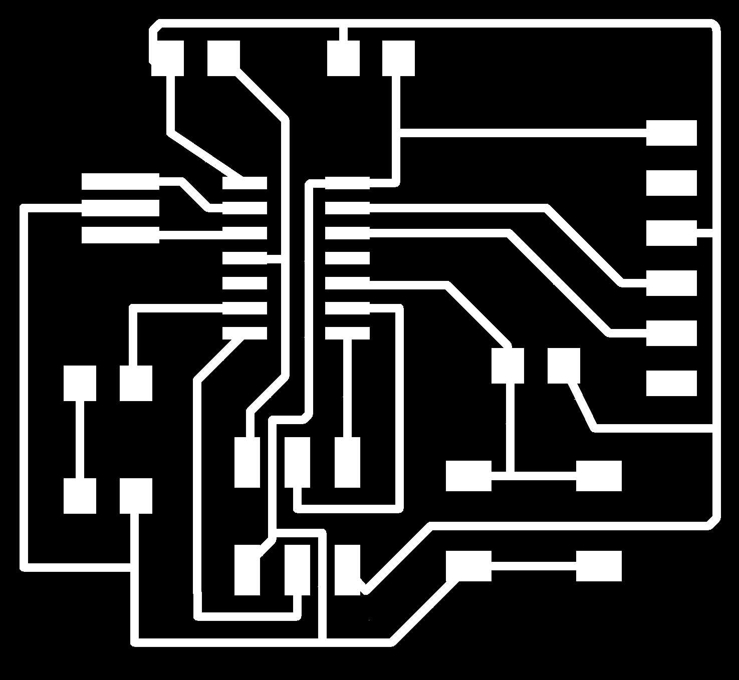
Before I can mill the board, I have to export as a png. I don't want the names and labels of the parts, so I go to Layers and just activate the 1st layer. This gives me the trace, which I need for my rml file. While exporting, I need to amkes sure, I have a high resolution.The minimum is 1000 dpi, so I am using this. Another thing is to select >monochrome, since I just need the black and white image.

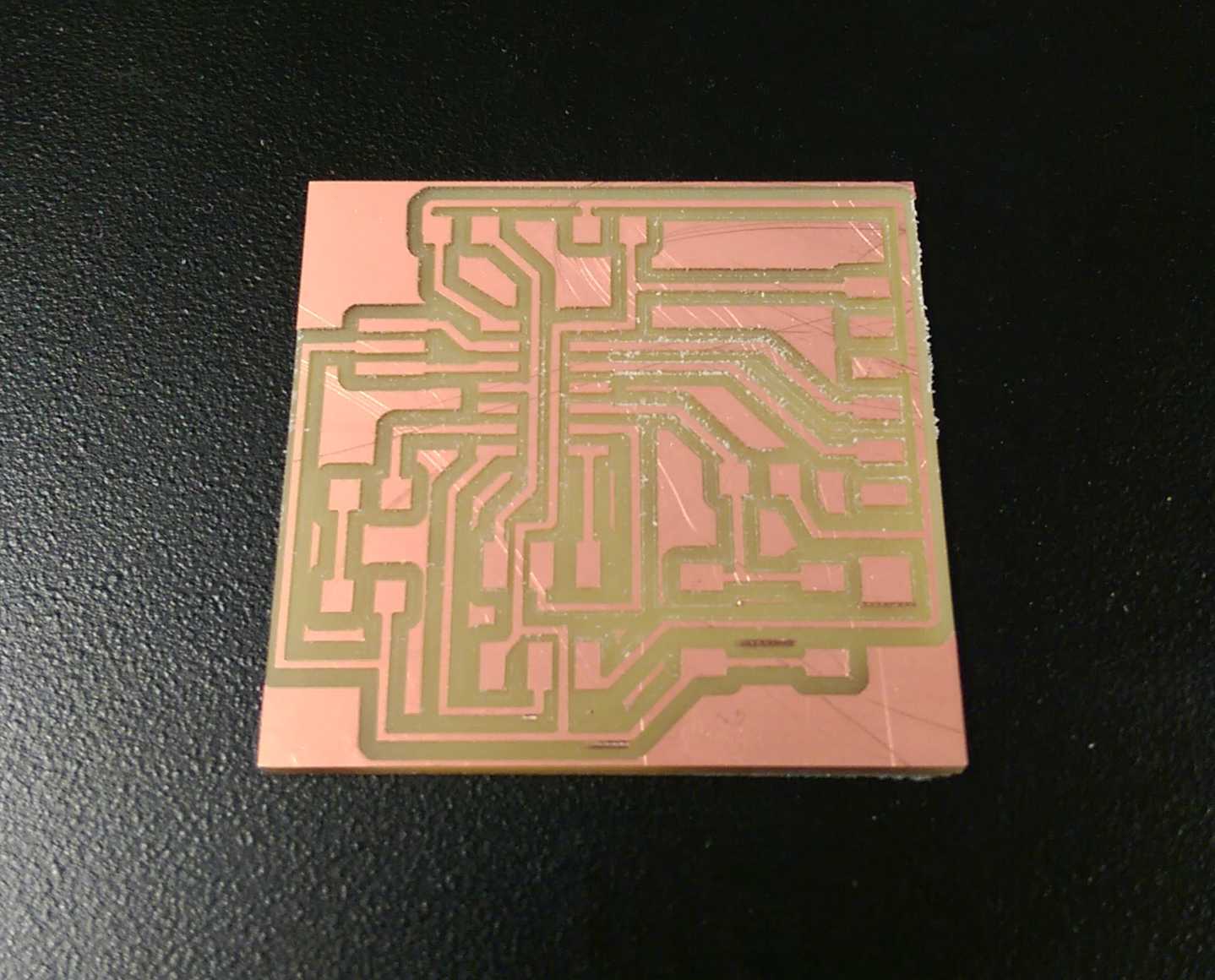
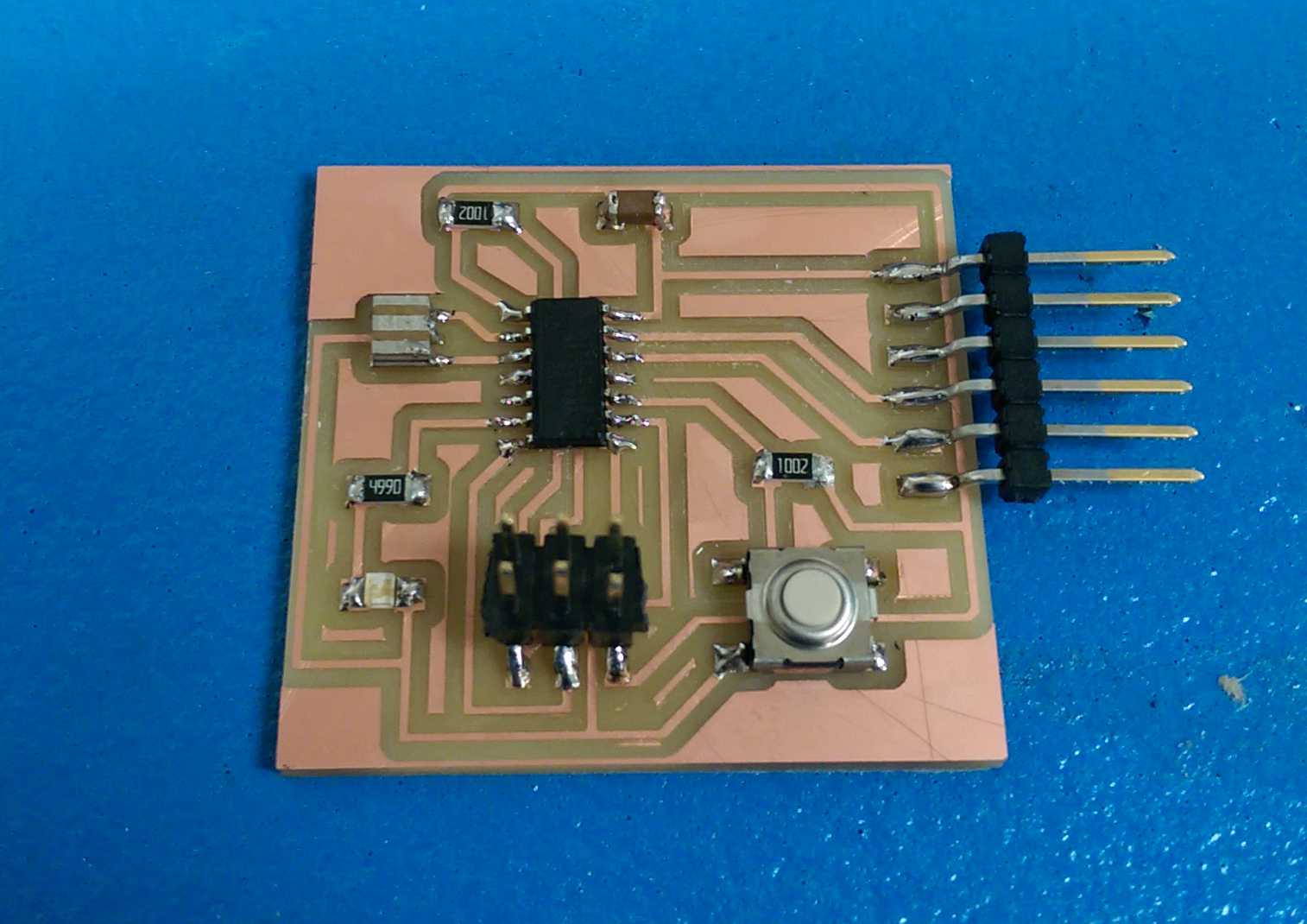
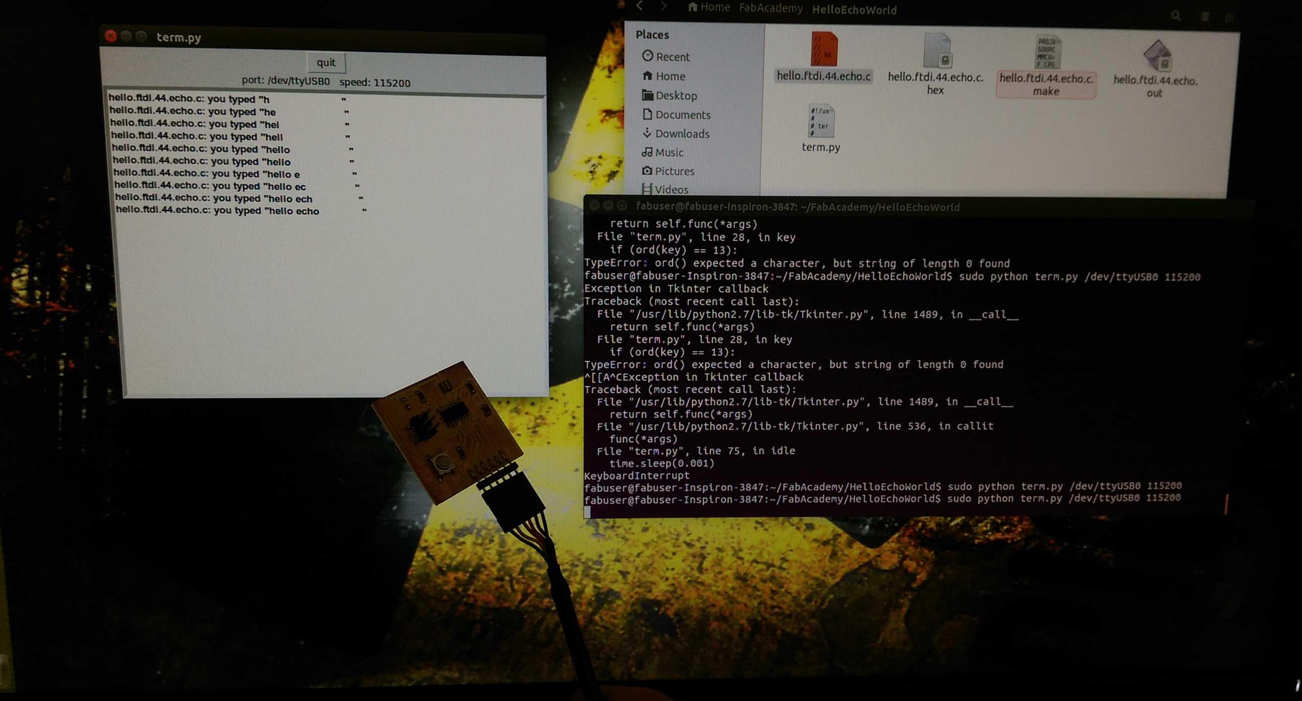
Here is the board fresh from milling and after soldering. Unfortuantely I did not have all parts, so I improvised. I used a 8 Mhz crystal (the only one available) and I bent the pins of both headers 90 degree, that I can solder them on the board. It worked pretty well and the next step is to program it.
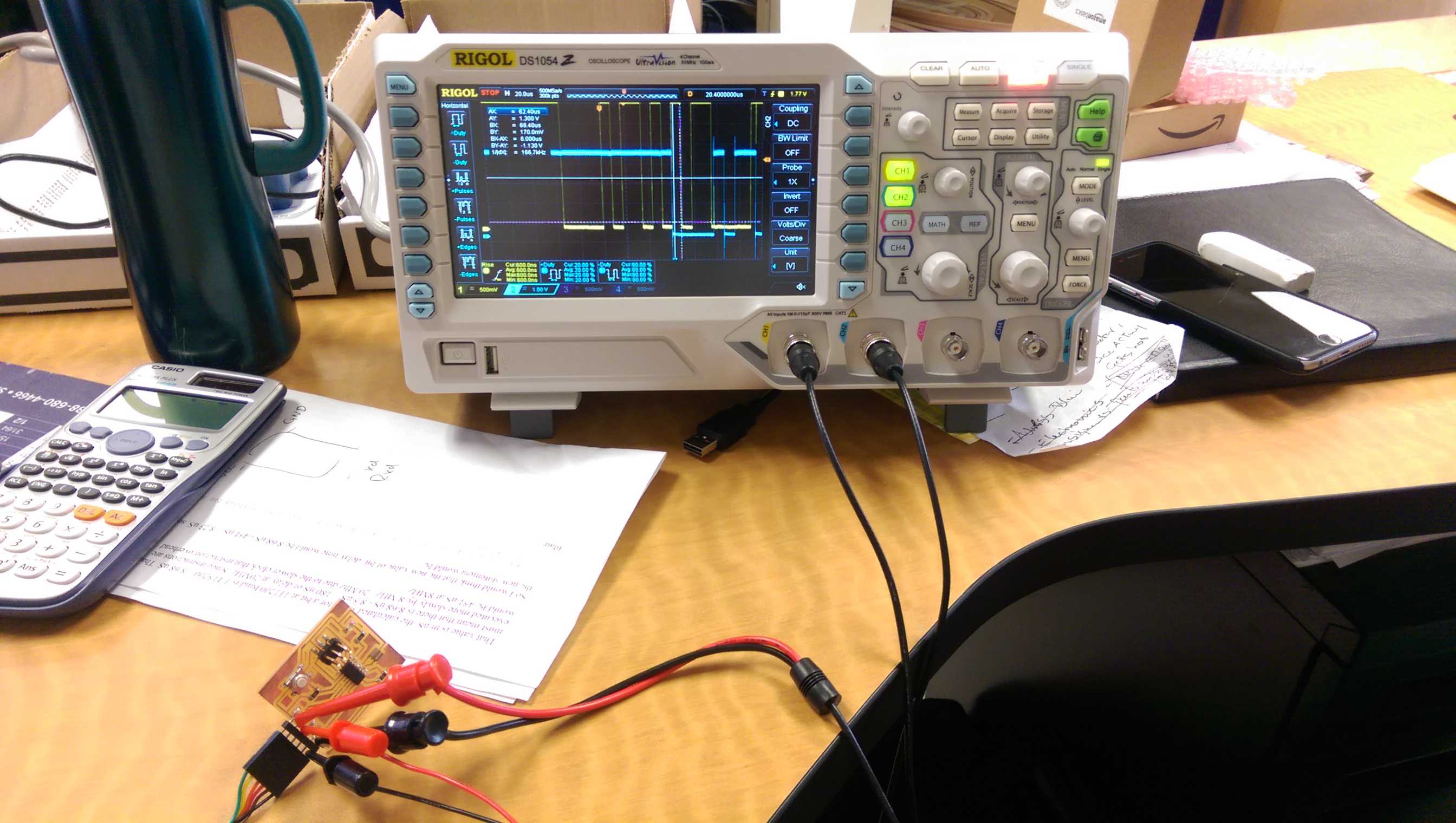
I sent some characters via serial monitor from the Arduino suite and I measured the lenght of 8.7 µs (this are the 8.68 µs) of the incoming bit and 9.1 µs out. I subtracted the ratio of both from 8.68 µs and got 7.85 µs as a new delay time. And it works!
Go to top