Week 4 - Make an in-circuit programmer by milling the PCB
The assignment of the fourth week is to mill a circuit with the Roland SRM-20
mill. We shall use also the Fabmodules to send the print job. Fisr of all, I am having trouble with the Ubuntu-Update.
After updating the controling computer OS to 16-4-0-4 the graphics driver has not been installed. I need to figure out, how to do so manually.
After spending too much time on trying to get it up and running again, I decided to use the Roland software,
which came with the machine.
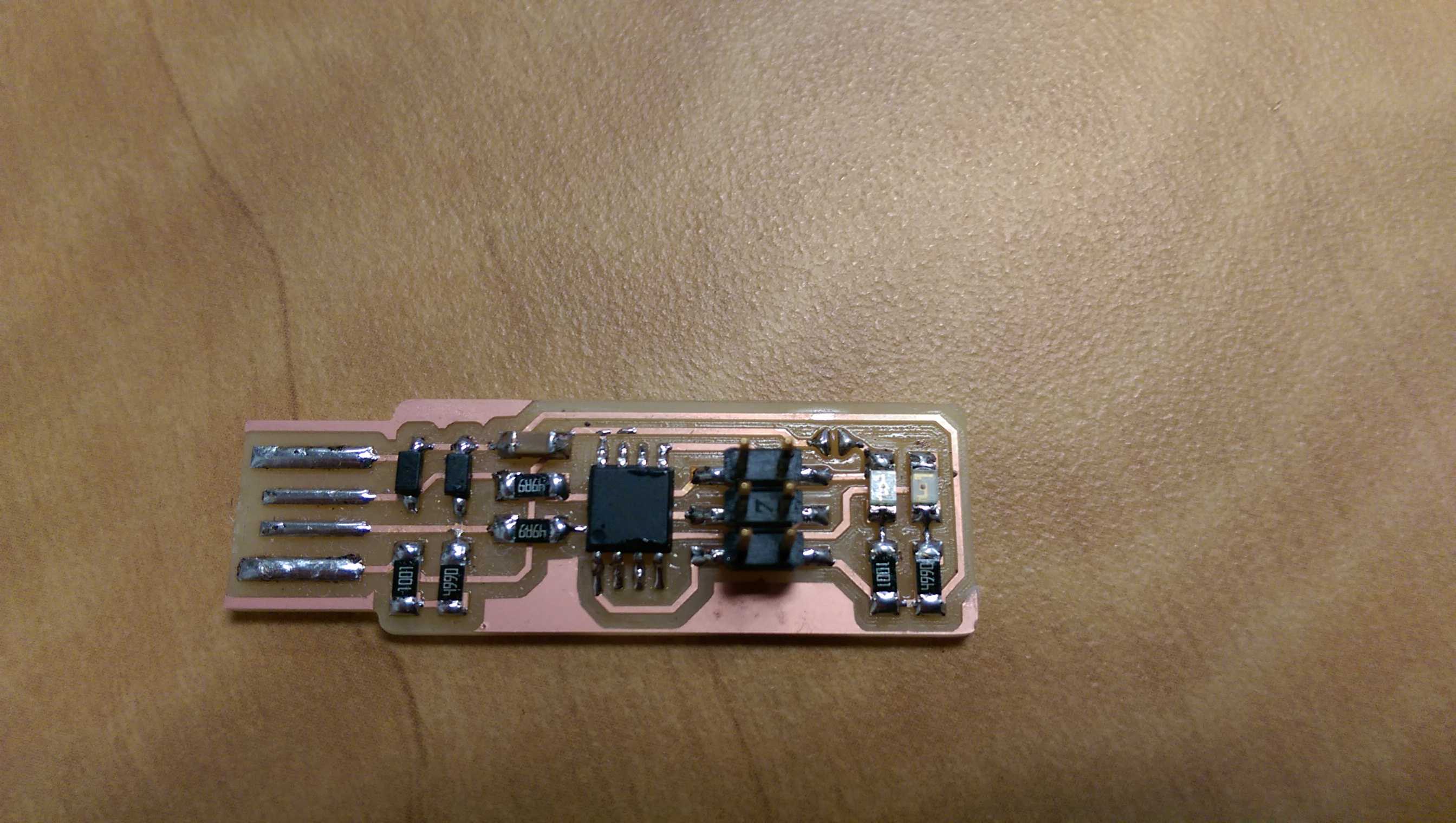
I have decided to make the
FabTinyISP.
On the page are already the png files for the outline and the traces. Since the Fabmoduls ar not really working (I can't connect
the Mill to the system), I found a way to work around that means the guys in the Fab Lab Kamakura they
have found a solution. After a while digging in the web, I have found a similar description in the online documentation of the
Fab Academy, there is a good tutorial which
describes the process.
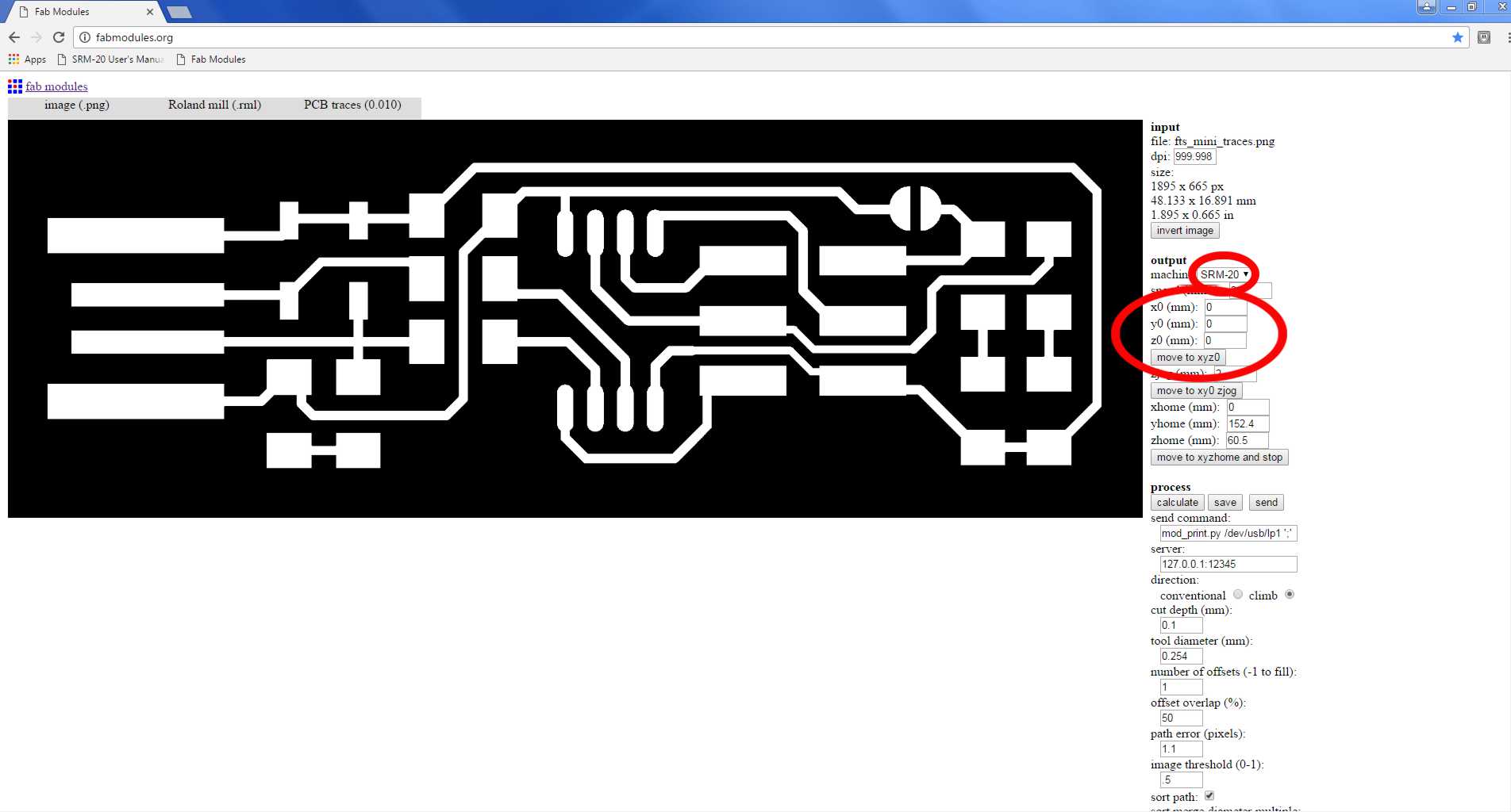
I am using a windows computer for this, with a Roland SRM-20 connected. First I go to fabmodules.org and load the png file in input format. Then I choose the output format roland mill (.rml) and the proces.
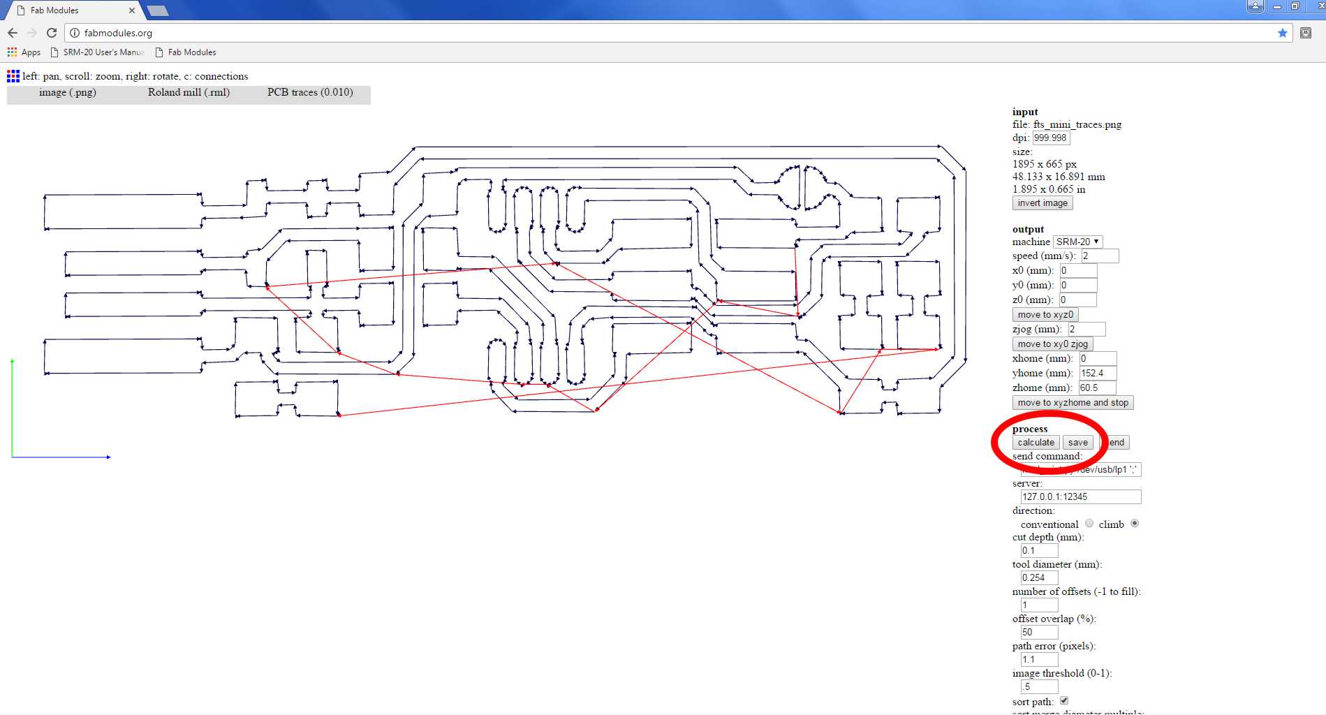
I choose PCB traces (1/64) for the circuit and PCB outline (1/32) for the cut of the bord. Then I choose the machine SRM-20 and most important set x+y+z+0!!!
After that I push calculate to get the toolpathways and save it as .rml file.
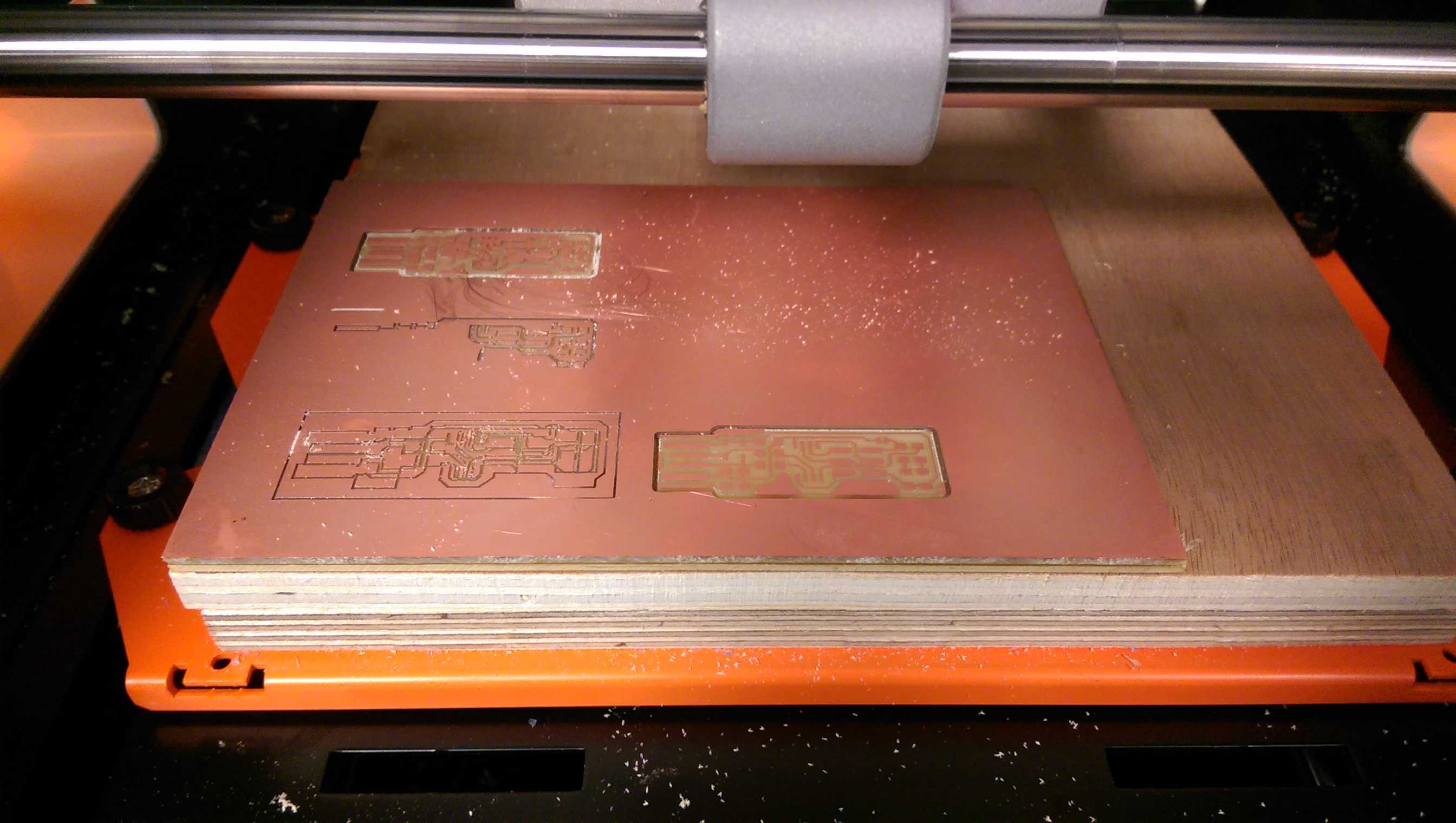
I fix the PCB board with double sided tape on the sacrifical board in the mill. Make sure, that the double sided tape is not overlapping and that the board is even.
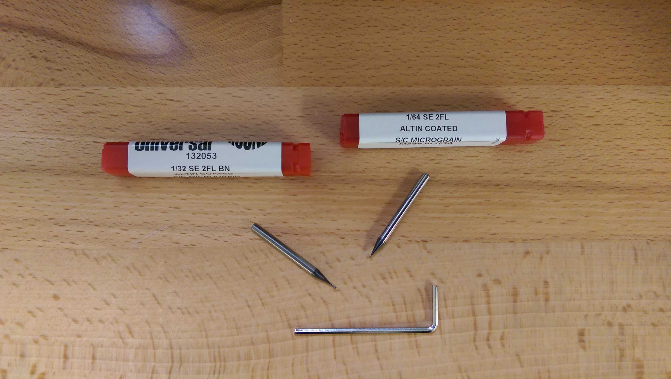
I mount the proper drill bit to the mill using the allen key. As mentioned above, for tarces I am using the 1/64 and for the cut the 1/32 bit. I tighten it just a bit, not to strong.
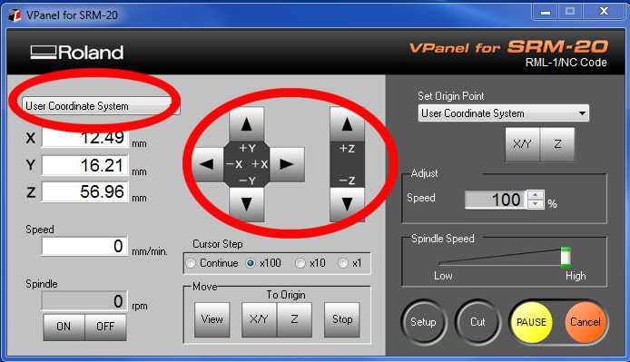
Then I open the Roland software VPanel. I choose 'User coordinate system" and move the mill-head with x and y buttons to my desired position and set the bit just a little above
the plane. I open the screw on the millhead and slowly let it down to the plane. After that I click x/y and z in the panel 'Set Origin Point' and set this point to my starting point. Make sure,
that there is enough room and leave some 5 mm to the edges of the board.
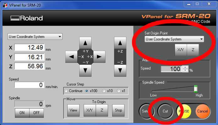
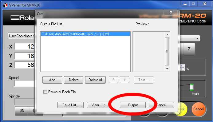
The I load the .rml file by hitting the "cut' button. By clicking "output" the mill starts working.
Milling in the name of...I needed several attempts to get it right but eventueally I did.
I cleaned the board, gathered all the SMD-components and started to solder.
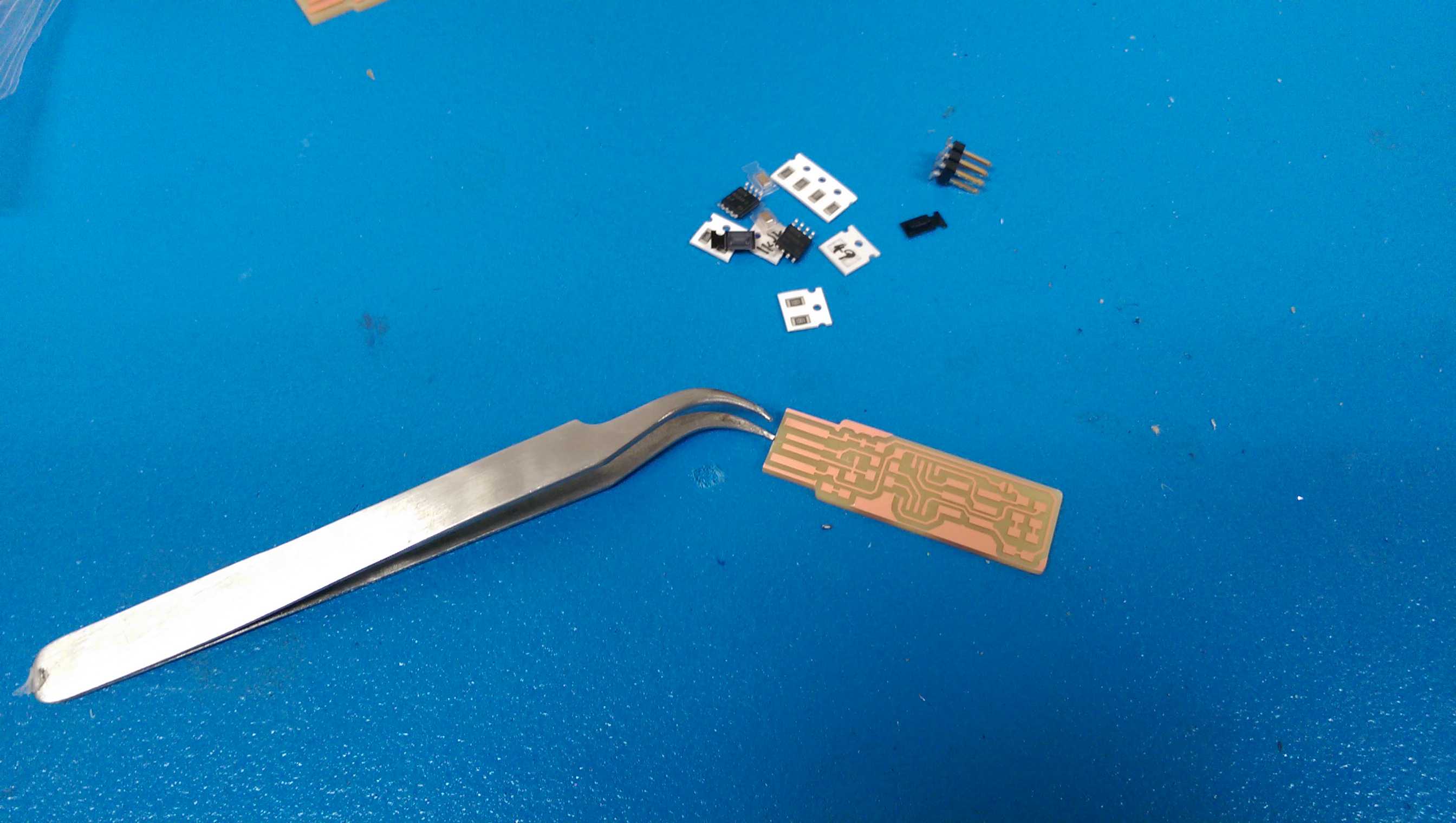
There was a tiny bit of copper left at the tip of the board, where the USB connection is. I needed to remove it with a knife. The soldering was pretty straight forward, thanks to the very detailed description of
FabTinyISP.
Make sure, that you have the right orientation of the diodes (the line represents the cathode) and LED's (same thing). It helped, to put a little solder on one pad and 'fix' the part with the solder iron
before I soldered it completely. To install the ISP as last part is helpful, since it is in the way otherwise. I am looking forward to test my board.
To test my board, I need to program it. Therfore I need a programmer and the right software to use it.
I followed the instructions from Brian on FabTinyISP. I used a machine with
Ubuntu LTS 16.04 and just installed avrdude.
sudo apt install avrdude gcc-avr avr-libc make
Avrdude is a free software to program Atmel AVR microcontrolers. The handling is quite easy, if you
are using Linux. There is a good documentation in the web about using the
Avrdude. To program it, I need another programmer. I used the AVRISPmkII, which I had in the Lab.
You need to change that in the Makefile according to the instructions from Brian. After uploading the source code
fts_firmware.hex with
sudo make flash
to the chip, I need to test the board. I unplugged evrything and plugged the board in the PC. I used
lsusb, to list my devices and it showed 'USBtiny'. Hooray, it worked!
After confirming the functionality of the board, I burned the fuses. First with the command
sudo burn fuses
then I unsoldered the conncetion on the junction and run
sudo rstdisbl
to disable the option, to reprogram this board ever again (except I replace the Attiny).
That is it, I have now a programmer for the upcoming assignements in the Fabacademy.