Week 10 - Output devices
In this week I am designing and my own microcontroller-board to operate an output device. Since I have a servo and the proper voltage regulator at hand, I will go with this.
Designing in Eagle
I can use my knowledge from the past weeks to make another board. Eagle has an update...horray! But I nedd to copy the fab-library in the lbr folder, since the update installs by default in a different folder. After having this solved, I have decided to go for the Servo motor board. Before starting, I have tested it with pulse lengths between 1.5 ms (corresponds to 90 degree turning) and 2 ms (corresponds to 180 degree turning).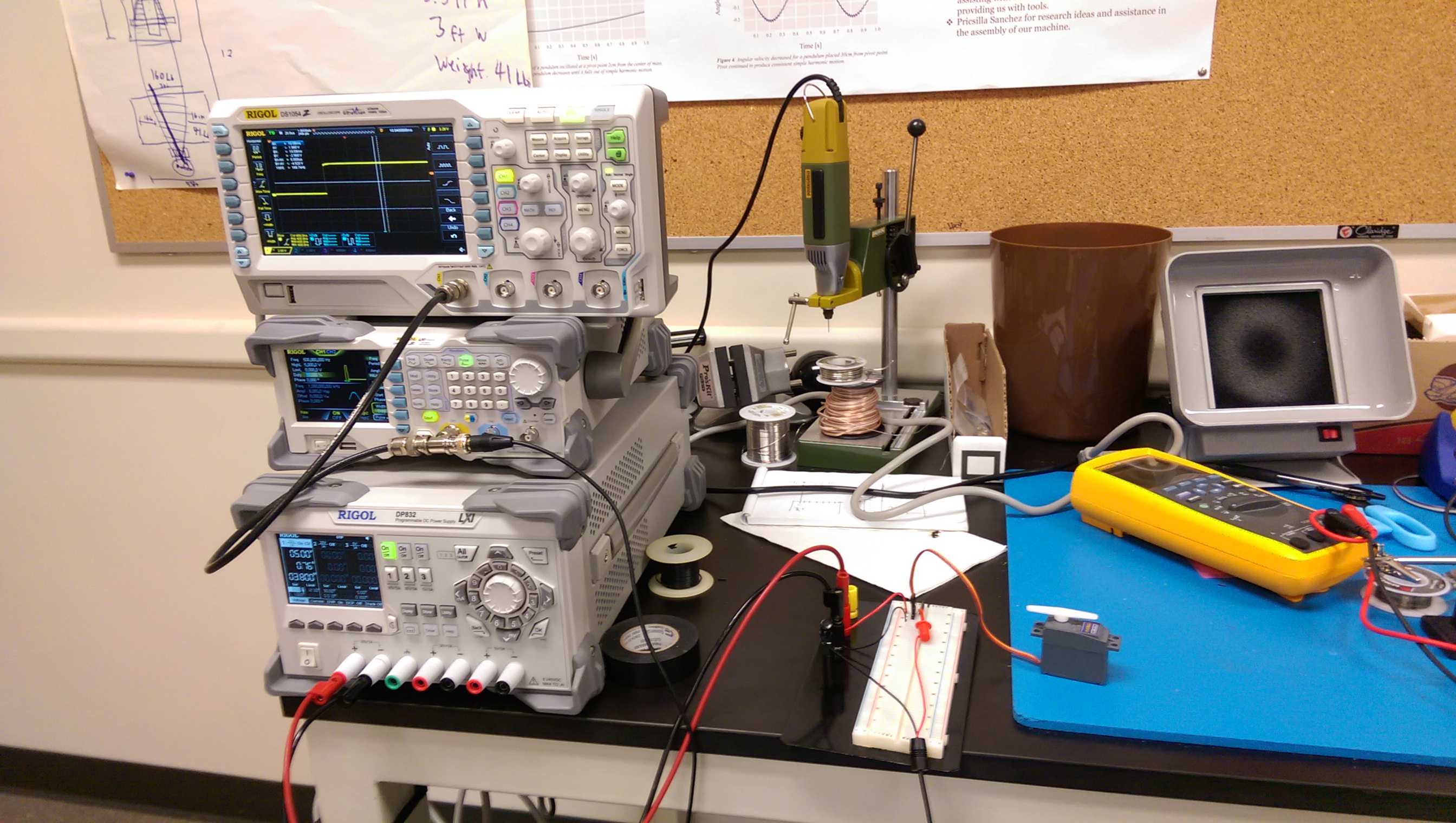
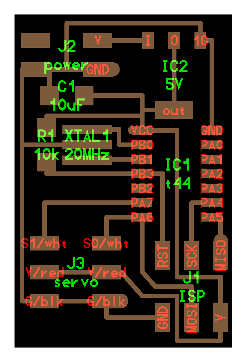
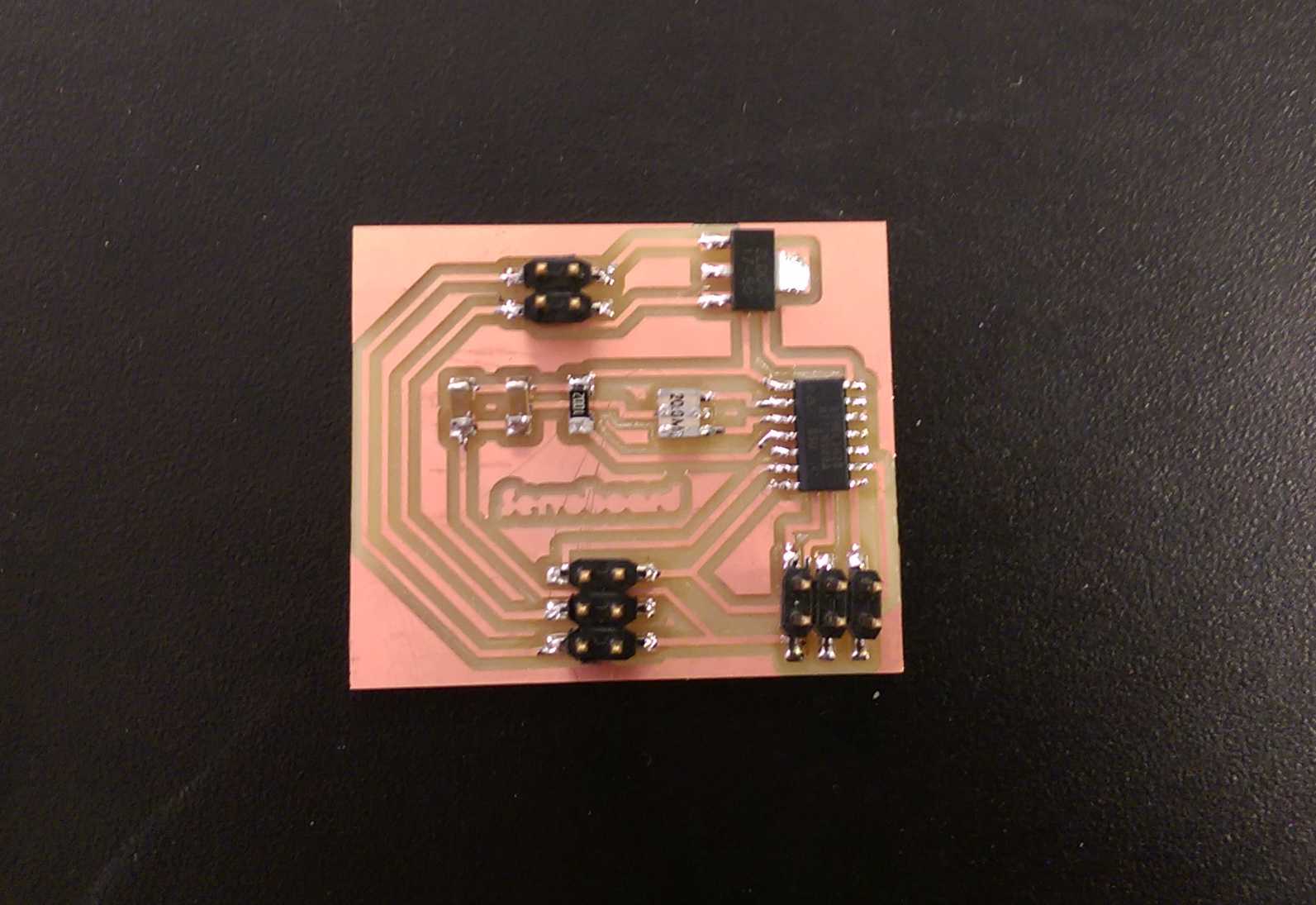
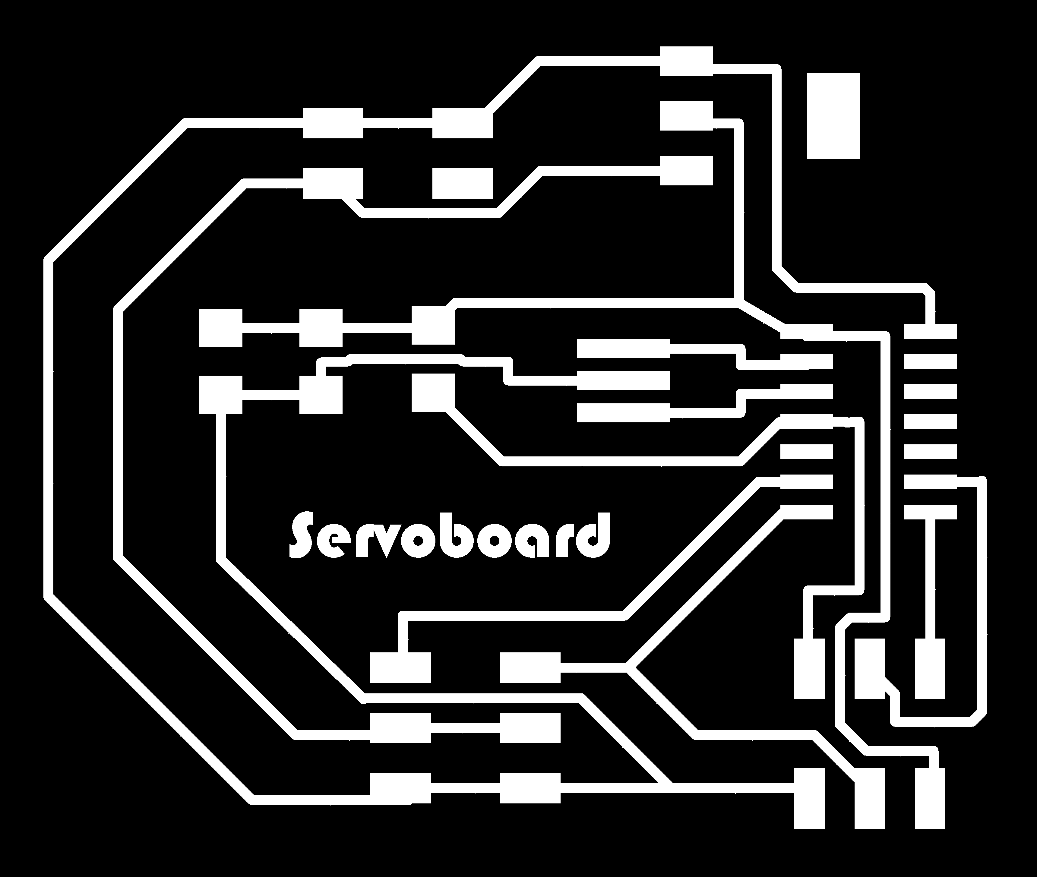
Now I have made the board. I followed basically the design what Neil has put on the webpage, with some exceptions, though. I figured out, that three traces under the ATTiny44 won't work with a bitsize of 1/64 (0.016 inch) in our SRM-20. I have made a new design and milled it.
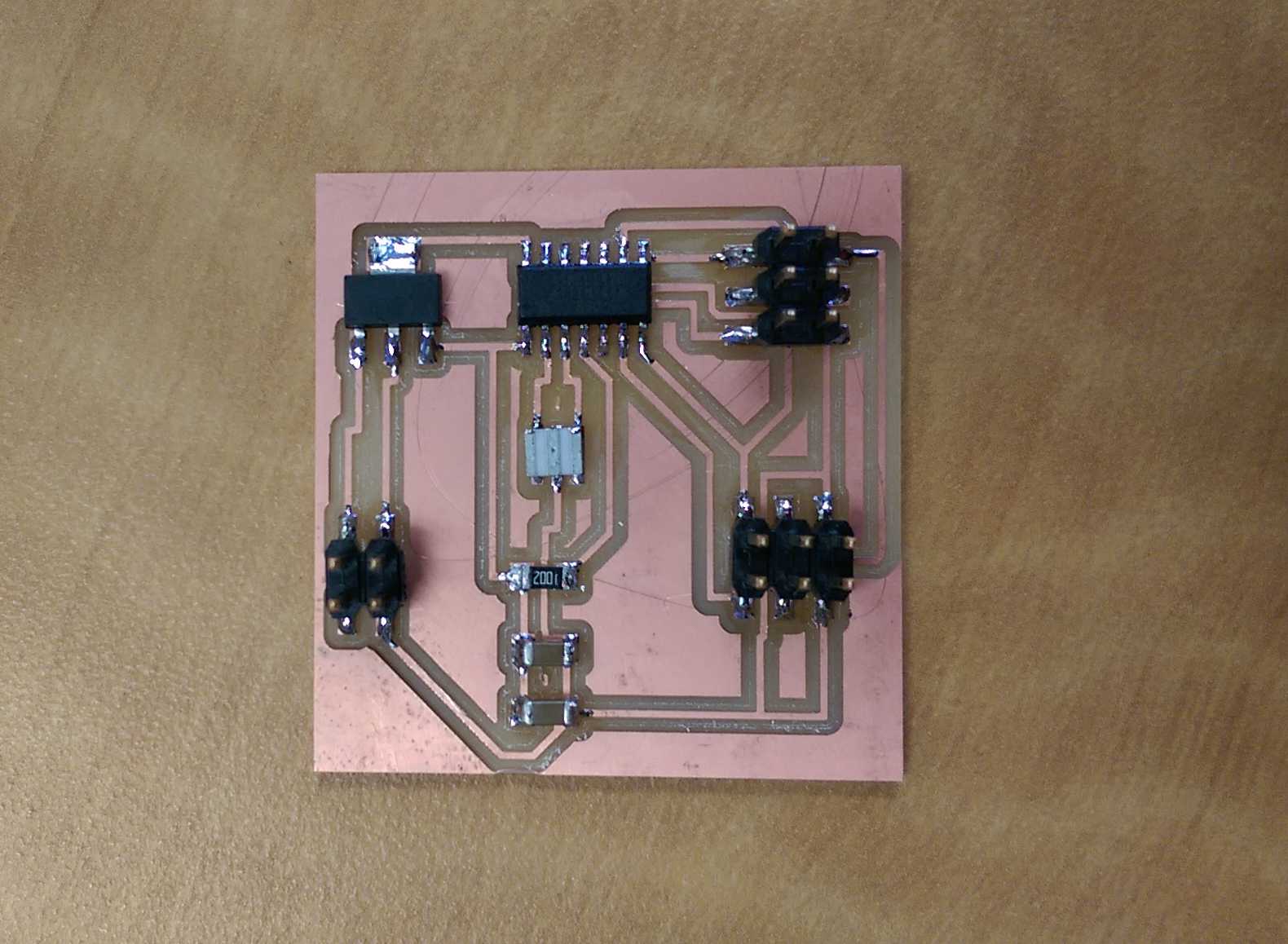
As I tested it, I figured out, that there was another problem. The voltage converter in Neil's design was not the one, which I had in the Lab. The result of this little mistake was, that I fried the Attiny and the voltage converter. Neil used the 2B47 L53B and I the ZLDO 1117. The pin assignements are different and therefore I shorted the board. I digged into Eagle and reassigned the pins, because both stablizer have the same SMD footprint SOT223. I have made another board and changed te pins but I fried it again. Fabio Ibarra from the Fab Academy 2016 ran into the same problem and thanks to his documentation, I have made another board. The problem was, that my previous designs the input voltage had a direct connection to Vcc of the ATTiny. The meaing of the voltage converter is, to give a certain stable output-voltage, no matter what is on the input side (to a certain ammount of course, since a converter has an upper input limit). The converter provides 5V for my ATTiny form the input volatage for the servos 9V. This voltage is direct transferred to the servos and the ATTiny gives the pulses on the signal input which tells the servo to move. According to the length of the pulse, the servo moves a certain angle (Pulse-width-modulation).
I used my FabISP from week 4 to load Neil's code for one servo and used a bench top power supply as power source.
And I loaded the one for two servos.
Nice, when things finally working! :) Here are my board files. The traces and the outline. Go to top