Week 15
Networking and Communication

The fifteenth lecture on Wednesday May 10th was about Networking and Communication: serial bus, ISO layers, phisical media, modulation, channel sharing, errors, networking, radio. Assignment given by Neil for this fifteenth week was:
- Design and build a wired &/or wireless network connecting at least two processors
Designing and build a wired network connecting two processors
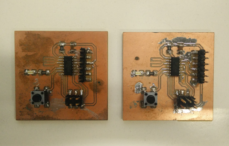
After exploring different network types, not having technical or engineering background, I decided to take it easy and build a two nodes network based on two echo hello-world boards, and make them communicate through their own serial interface: pushing buttons on the first one makes the LED on the second one become more on less bright. I won't go through the whole PCB production process since I already had the two boards from Week 06.
About the firmwares: for the first node I modified firmare from Week 08, adding support for another button and make it write a standard string (different for each button: "dim_set:+;" and "dim_set:-;"); for the second node I wrote a program that receives message through serial interface: when receives "dim_set:+;" brightens up the LED, when receives "dim_set:-;" lowers LEDs brightness. LEDs is commanded through PWM and every single step is "50".
Node-A (input) code
#include <SoftwareSerial.h>
SoftwareSerial mySerial(1, 0);

const int buttonPlus = 7;
const int buttonMinus = 6;
const int ledPin =  8;

int buttonPlusState = HIGH;
int buttonMinusState = HIGH;

void setup() {
  // initialize serial:
  mySerial.begin(9600);
  // initialize the LED pin as an output:
  pinMode(ledPin, OUTPUT);
  // initialize the pushbutton pin as an input:
  pinMode(buttonPlus, INPUT);
  pinMode(buttonMinus, INPUT);
  // Pull up resistors
  digitalWrite(buttonPlus, HIGH);
  digitalWrite(buttonMinus, HIGH);
}

void loop(){
  // read the state of buttons
  buttonPlusState = digitalRead(buttonPlus);
  if (buttonPlusState == LOW) {
    digitalWrite(ledPin, HIGH);
    mySerial.print("dim_set:+;");
    mySerial.println("\n");

    while (buttonPlusState == LOW) {
      buttonPlusState = digitalRead(buttonPlus);
    }

    digitalWrite(ledPin, LOW);
    delay(250);
  }

  buttonMinusState = digitalRead(buttonMinus);
  if (buttonMinusState == LOW) {
    digitalWrite(ledPin, HIGH);
    mySerial.print("dim_set:-;");
    mySerial.println("\n");

    while (buttonMinusState == LOW) {
      buttonMinusState = digitalRead(buttonMinus);
    }

    digitalWrite(ledPin, LOW);
    delay(250);
  }
}
Node-B (output) code
#include <SoftwareSerial.h>
////////////////
// Setup vars //
////////////////

SoftwareSerial mySerial(1, 0);
// Pin controlling the light
int led = 8;
// Boot light brightness
int brightness = 0;
// Default fade step
int fade_step = 50;


////////////////////
// setup function //
////////////////////
void setup() {
    // Serial initialization
    mySerial.begin(9600);
    // Setting up the output pins
    pinMode(led, OUTPUT);
}


///////////////////
// loop function //
///////////////////
void loop() {
    // Check if there is stuff available in serial buffer
    while (mySerial.available() > 0) {

        // Received raw command var
        String raw_command = "";
        // Extract raw command
        raw_command = mySerial.readStringUntil(';');

        // Look for valid "dim_set" command
        int dimset_command_pos = raw_command.lastIndexOf("dim_set:");
        // If there is a valid "dim_set" command then handoff to dimSetCommand function
        if (dimset_command_pos != -1 ) {
            String dimSet_value = extractValue(raw_command.substring(dimset_command_pos));
            dimSetCommand(dimSet_value);
        }
    }
}


////////////////////////////
// dimSetCommand function //
////////////////////////////
boolean dimSetCommand(String command_string) {
    // Received new brightness
    int new_brightness = 0;
    // Check if a change of brightness is required
    bool new_brightness_flag = false;
    // Extracted command value
    String brightness_command_value = "";
    brightness_command_value = command_string.substring(8);

    if (brightness_command_value == "+") {
        new_brightness = brightness + fade_step;
        new_brightness_flag = true;
    }
    if (brightness_command_value == "-") {
       new_brightness = brightness - fade_step;
       new_brightness_flag = true;
    }


    if (new_brightness_flag) {
        if (new_brightness <= 0) {
          new_brightness = 0;
        }
        if (new_brightness >= 250) {
          new_brightness = 250;
        }
        brightness = new_brightness;
        analogWrite(led, brightness);
        mySerial.print("dim level: ");
        mySerial.println(brightness);
        return true;
    }

    return false;
}


///////////////////////////
// extractValue function //
///////////////////////////
String extractValue(String raw_value) {
  int value_pos = raw_value.indexOf(";");
  if (value_pos != -1) {
    String extracted_value = raw_value.substring(0, value_pos -1);
    return extracted_value;
  }
  return raw_value;
}


/////////////////////////
// isValidInt function //
/////////////////////////
boolean isValidInt(String str) {
    boolean isInt = false;
    for(byte i = 0; i < str.length(); i++) {
        if(isDigit(str.charAt(i))) {
            isInt = true;
        } else {
            return false;
        }
    }
    return isInt;
}
Here's a "Hero Shot" of the wired network installation
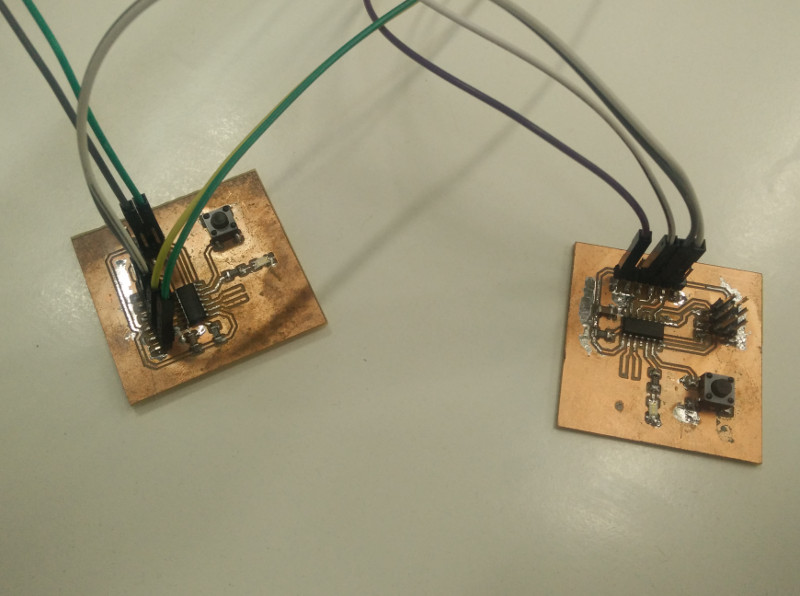
and here's a small "Hero Video"
Designing and build a wired network connecting more than two processors
In order to build a network connecting more than two processors, it's necessary to add something about addressing the message for one specific microcontroller (each one needs to be able to recognize it is being talked to, and the message is not meant for another microcontroller). I decided to build a network in some ways inspired to IP protocol: just based on a Simplex TTL serial RS-232 connection and therefore reduced on a bare-minimum scale.
About protocol rules, I decided address-size to be equal to one single byte; a network like this can have a total of 254 nodes, since a single byte can assume 256 different values: one address ("255") is reserved for broadcasting purpose, one address ("0") is reserved for the transmitter even if not used, the remaining addresses ("1-254") are available for the nodes. Furthermore, I decided standard message to be composed of two parts: address and command ("addr:$number;command:$value;"). So I modified transmitter code as follows:
- Each transmitter button is meant to generate messages to be trasmitted to a given address
- Pressing a button for a short time sends increase-LED-brightness message addressed to a specific microcontroller over the network
- Pressing a button for a long time sends decrease-LED-brightness message addressed to a specific microcontroller over the network
Node-A (input) code
#include <SoftwareSerial.h>
SoftwareSerial mySerial(1, 0);

const int buttonPlusA = 7;
const int buttonPlusB = 6;
const int ledPin =  8;

int buttonPlusAState = HIGH;
int buttonPlusBState = HIGH;

void setup() {
    // initialize serial:
    mySerial.begin(9600);
    // initialize the LED pin as an output:
    pinMode(ledPin, OUTPUT);
    // initialize the pushbutton pin as an input:
    pinMode(buttonPlusA, INPUT);
    pinMode(buttonPlusB, INPUT);
    // Pull up resistors
    digitalWrite(buttonPlusA, HIGH);
    digitalWrite(buttonPlusB, HIGH);
}

void loop(){
    // read the state of buttons
    buttonPlusAState = digitalRead(buttonPlusA);
    if (buttonPlusAState == LOW) {
        digitalWrite(ledPin, HIGH);
        unsigned int count = 0;

        while (buttonPlusAState == LOW) {
            buttonPlusAState = digitalRead(buttonPlusA);
            count ++;
            delay(50);
            if (count == 21) {
                digitalWrite(ledPin, LOW);
            }
        }

        if (count <= 20) {
            mySerial.println("addr:001;dim_set:+;");
        } else {
            mySerial.println("addr:001;dim_set:-;");
        }

        digitalWrite(ledPin, LOW);
        delay(250);
    }

    buttonPlusBState = digitalRead(buttonPlusB);
    if (buttonPlusBState == LOW) {
        digitalWrite(ledPin, HIGH);
        unsigned int count = 0;

        while (buttonPlusBState == LOW) {
            buttonPlusBState = digitalRead(buttonPlusB);
            count ++;
            delay(50);
            if (count == 21) {
                digitalWrite(ledPin, LOW);
            }
        }

        if (count <= 20) {
            mySerial.println("addr:002;dim_set:+;");
        } else {
            mySerial.println("addr:002;dim_set:-;");
        }

        digitalWrite(ledPin, LOW);
        delay(250);
    }
}
I also modified receiver code as follows:
- Receiver parses serial data, looking for a valid address ("addr:$number")
- If receiver finds an address corresponding to local address (defined at the beginning) or broadcast address, looks for a command
- If receiver doesn't find any address or finds an address not corresponding to local address, drops message
Node-B (output) code
#include  <SoftwareSerial.h >
////////////////
// Setup vars //
////////////////

SoftwareSerial mySerial(1, 0);
// Pin controlling the light
int led = 8;
// Boot light brightness
int brightness = 0;
// Default fade step
int fade_step = 50;
// Local address
byte local_address = 001;


////////////////////
// setup function //
////////////////////
void setup() {
    // Serial initialization
    mySerial.begin(9600);
    // Setting up the output pins
    pinMode(led, OUTPUT);

    delay(local_address*50);
    mySerial.print("Comm_Output - Address: ");
    mySerial.println(String(local_address));
}


///////////////////
// loop function //
///////////////////
void loop() {
    // Resetting command address
    byte command_address = 0;
    // Check if there is stuff available in serial buffer
    while (mySerial.available() > 0) {

        // Received raw command var
        String raw_command = "";
        // Extract raw command
        raw_command = mySerial.readStringUntil(';');

        // Read the address received in the command
        byte command_address = address_LookUp(raw_command);

        // If the command address is valid and match the local address then execute the next command
        if (command_address == 255 || command_address == local_address) {
            raw_command = mySerial.readStringUntil(';');
            dimSet_LookUp(raw_command);
        } else {
            // Otherwise put the next command in the trash bin
            mySerial.readStringUntil(';');
        }
    }
}


/////////////////////////////
// address_LookUp function //
/////////////////////////////
byte address_LookUp(String raw) {
    // Look for valid "addr" command
    int address_command_pos = raw.lastIndexOf("addr:");
    // If there is a valid "address" command then read the value
    if (address_command_pos != -1 ) {
        String address_string_value = raw.substring(address_command_pos + 5, raw.length());
        // If the readed value is a string of only digits then convert it to int e return it
        if (isValidInt(address_string_value)) {
            return address_string_value.toInt();
        }
    }
    return 0;
}


////////////////////////////
// dimSet_LookUp function //
////////////////////////////
void dimSet_LookUp(String raw) {
    // Look for valid "dim_set" command
    int dimset_command_pos = raw.lastIndexOf("dim_set:");
    // If there is a valid "dim_set" command then handoff to dimSetCommand function
    if (dimset_command_pos != -1 ) {
        String dimSet_value = raw.substring(dimset_command_pos + 8, raw.length());
        dimSetCommand(dimSet_value);
    }
}


////////////////////////////
// dimSetCommand function //
////////////////////////////
boolean dimSetCommand(String brightness_command_value) {
    // Received new brightness
    int new_brightness = 0;
    // Check if a change of brightness is required
    bool new_brightness_flag = false;

    if (brightness_command_value == "+") {
        new_brightness = brightness + fade_step;
        new_brightness_flag = true;
    }
    if (brightness_command_value == "-") {
       new_brightness = brightness - fade_step;
       new_brightness_flag = true;
    }


    if (new_brightness_flag) {
        if (new_brightness <= 0) {
          new_brightness = 0;
        }
        if (new_brightness >= 250) {
          new_brightness = 250;
        }
        brightness = new_brightness;
        analogWrite(led, brightness);
        mySerial.print("dim level: ");
        mySerial.println(brightness);
        return true;
    }

    return false;
}


/////////////////////////
// isValidInt function //
/////////////////////////
boolean isValidInt(String str) {
    boolean isInt = false;
    for(byte i = 0; i < str.length(); i++) {
        if(isDigit(str.charAt(i))) {
            isInt = true;
        } else {
            return false;
        }
    }
    return isInt;
}
Here's a "Hero Shot" of the new wired network installation
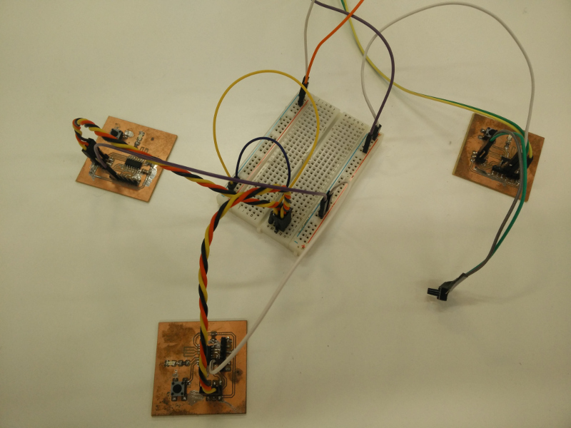
and here's a small "Hero Video"
Source files
- snode-A.ino -Arduino IDE output INO File (Single node Transmitter)
- snode-B.ino -Arduino IDE output INO File (Single node Receiver)
- mnode-A.ino -Arduino IDE output INO File (Multiple node Transmitter)
- mnode-B.ino -Arduino IDE output INO File (Multiple node Receiver)