Week 13
Input Devices

The thirteenth lecture on Wednesday April 26th was about Input Devices: types and communication, switch (button, slide), motion, distance (sonar, optical), magnetic field, temperature, light (IR, visible, phototransistor), acceleration-orientation-rotation, sound, step response, vibration, force, image. Assignment given by Neil for this thirteenth week was:
- Measure something: add a sensor to a microcontroller board that you have designed and read it
Designing a microcontroller board including a flow sensor control
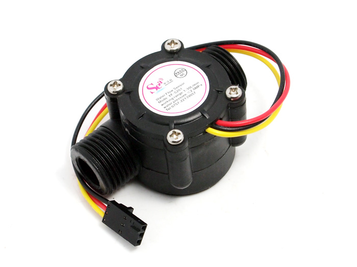
Between the various output types described by Neil during Week 13 lecture, and despite the fact that Neil's preferred and suggested ones to work with "in-case-of-doubt" were the step-response sensors (covering a very wide range: from resistance to capacitance, inductance, position, pressure, proximity, tilt, acceleration, humidity; event until touchpad and multitouch). I decided to focus on the control of a G1&2" Water Flow Sensor YF-S201, thinking it could also maybe useful to integrate my previously designed servo motor output board, in order to obtain someway a prototype of a very basic aquaponics control board module. This sensor consists in a plastic valve body, a water rotor, and a hall-effect sensor.
Starting point for this assignment was the previous built servo output device board; I used KiCAD EDA and opened Eeschema Module. I removed the button from Port PA7, then I connected the Pin headers to +5V, GND and Port PA7 (Pin#6, renaming it "FLOW"), compatible with flow sensor (at least as reported on ATTiny 84-SSU microcontroller datasheet).
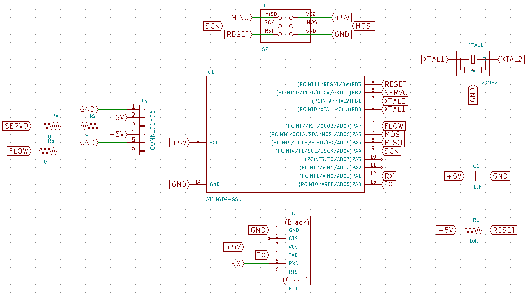
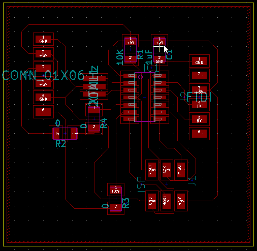
Then as usual, I went successfully through automatic schema Annotation, Electrical Rules Check (ERC) and, before exporting the NETlist, I associated components and footprints from libraries using KiCAD cvPCB Module; from the fab library I associated it to the 1x06SMD footprint. Here's the manual route result:
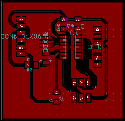
Here's with the filled zone, before SVG export
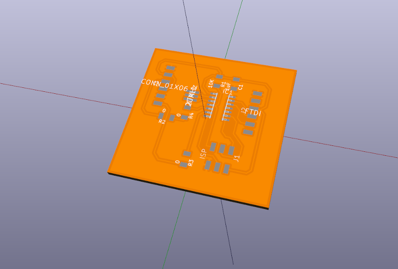
Here's is the KiCAD 3D render output
About the firmware, I took some inspiration from Adafruit Flow-meter example, then wrote the following code with Arduino IDE. I removed all serial commands (using interrupts together with software serial it's not so simple), all LCD commands (LCD not present in this case), and finally added commands for servo.
/*
 * Based on Liquid flow meter example code
 * by Adafruit <http://www.adafruit.com>
*/

#include <Servo.h>

// which pin to use for reading the sensor? can use any pin!
#define FLOWSENSORPIN 6

Servo myservo;  // create servo object to control a servo

// count how many pulses!
volatile uint16_t pulses = 0;
// track the state of the pulse pin
volatile uint8_t lastflowpinstate;
// you can try to keep time of how long it is between pulses
volatile uint32_t lastflowratetimer = 0;
// and use that to calculate a flow rate
volatile float flowrate;
// Interrupt is called once a millisecond, looks for any pulses from the sensor!
SIGNAL(TIMER0_COMPA_vect) {
    uint8_t x = digitalRead(FLOWSENSORPIN);
    if (x == lastflowpinstate) {
        lastflowratetimer++;
        return; // nothing changed!
    }

    if (x == HIGH) {
        //low to high transition!
        pulses++;
    }

    lastflowpinstate = x;
    flowrate = 1000.0;
    flowrate /= lastflowratetimer;  // in hertz
    lastflowratetimer = 0;
}

void useInterrupt(boolean v) {
    if (v) {
        // Timer0 is already used for millis() - we'll just interrupt somewhere
        // in the middle and call the "Compare A" function above
        OCR0A = 0xAF;
        TIMSK0 |= _BV(OCIE0A);
    } else {
        // do not call the interrupt function COMPA anymore
        TIMSK0 &= ~_BV(OCIE0A);
    }
}

void setup() {
   pinMode(FLOWSENSORPIN, INPUT);
   digitalWrite(FLOWSENSORPIN, HIGH);
   lastflowpinstate = digitalRead(FLOWSENSORPIN);
   useInterrupt(true);
}

void loop() {
    if (flowrate >= 10) {
        myservo.write(0);
    } else {
        myservo.write(180);
    }

    float liters = pulses;
    liters /= 7.5;
    liters /= 60.0;
    delay(100);
}
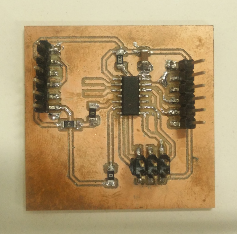
Here's the "Hero Shot" of the actual final flow board result, with flow sensor attached: milled, stuffed with components and programmed (for details see Week 04)
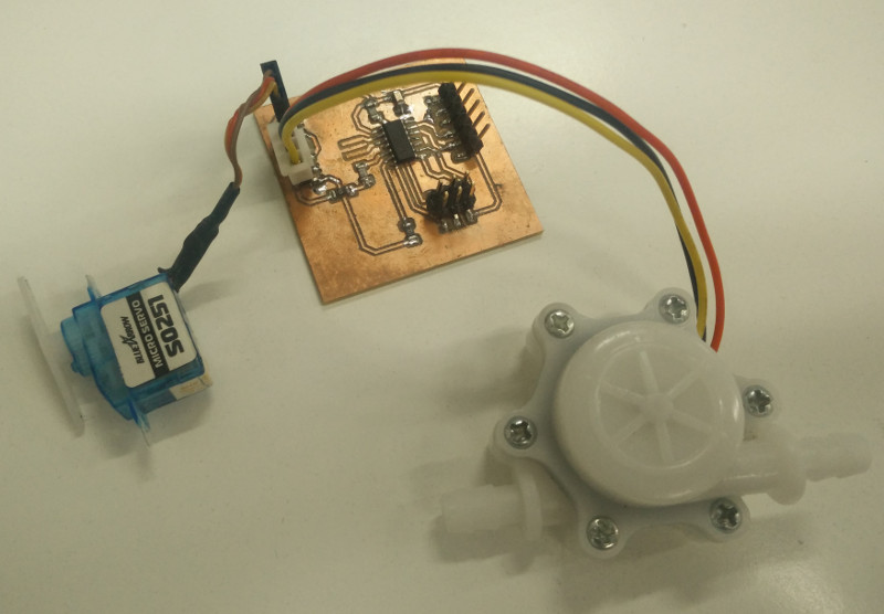
and here with flow sensor and servo actuator attached
Source files
- flow.sch -KiCAD Eeschema output SCH File
- flow.net -KiCAD Eeschema output NET File (Netlist)
- flow.kicad_pcb -KiCAD PcbNew output KICAD_PCB File
- flow-F.Cu.svg -KiCAD PcbNew output SVG File (Traces)
- flow-F.Cu.png -Inkscape output PNG File (Traces)
- flow-F.Cu.rml -Fabmodules output RML File (Traces)
- flow-Edge.Cuts.svg -KiCAD PcbNew output SVG File (Traces)
- flow-Edge.Cuts.png -Inkscape output PNG File (Traces)
- flow-Edge.Cuts.rml -Fabmodules output RML File (Traces)
- flow.ino -Arduino IDE output INO File