Week 04
Electronics Production
The fourth lecture on Wednesday February 15th was about Electronics Productions: different ways to manufacture PCBs with all the conductive tracks shaped in the correct way and all the electronic parts soldered in the correct position. Assignment given by Neil for this fourth week was:
- Make an in-circuit programmer by milling the PCB, then optionally trying other processes
Making an in-circuit programmer by milling the PCB
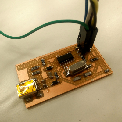
The in-circuit programmer introduced during Neil's lecture is the so called FabISP, a completely fab-able (designed for production within a FabLab) in-system programmer for AVR microcontrollers: AVR microcontroller was first introduced in 1996 as one of the first microcontrollers to use on-chip flash memory for program storage, as opposed to one-time programmable ROM, EPROM, or EEPROM. As explained by Neil toward the end of electronic-production lecture a FabISP can be programmed through another FabISP and AVRdude software which is released under GPLv.2 License, or through commercial programmers/debuggers like the Atmel-ICE and Atmel Studio software.
This week assignment consists in producing FabISP with the PCB milling method; in order to do this, it is important to understand the functioning of a precision (0,001 mm/step resolution) CNC milling machine: from the CAD model to the CAM end-mill route over the material to be milled, for a given machine model. More in particular, the given machine is the desktop CNC mill Roland Monofab SMR-20 which is present as recommanded machine for the FabLab Inventory and fully supported from Fabmodules Project (system independent browser-based CAM software).
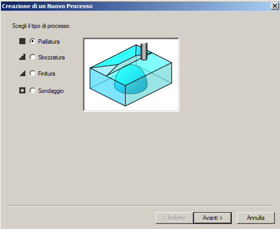
Before really starting with PCB milling, it's also important to make sure that spoil board is perfectly plane; so I milled SMR-20's MDF sacrificial base it with a 5mm square-shaped end-mill, using Modela Player 4 software.
Creating new process (surface levelling)
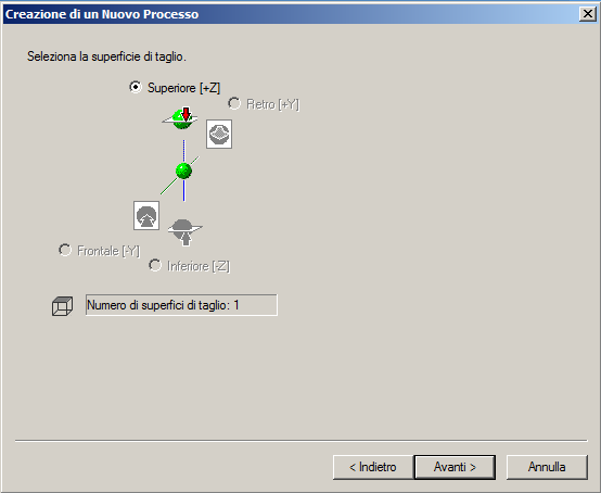
Selecting cutting surface (upper surface)
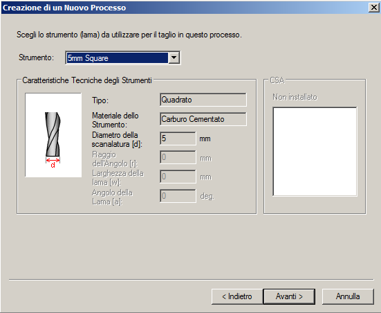
Selecting cutting tool (5mm square-shaped carbide bit)
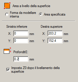
Selecting cutting area (203.2x152.4mm) and depth (0.2mm)
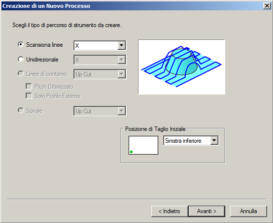
Selecting tool path (line scan, X axis)
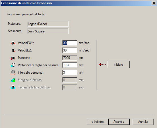
Selecting material (wood), X, Y and Z axis speed (30mm/sec), spindle (7000rpm)
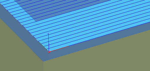
Checking tool path
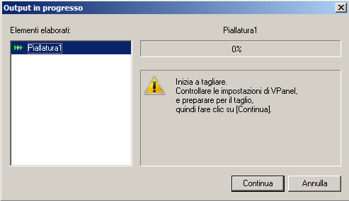
Cutting: ready...
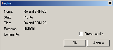
...start! CAM output is passed as an input to Roland VPanel software that's used to operate the modeling machine on the computer screen; it has functions to output cutting data and perform maintenance; it also displays error messages of the modeling machine.
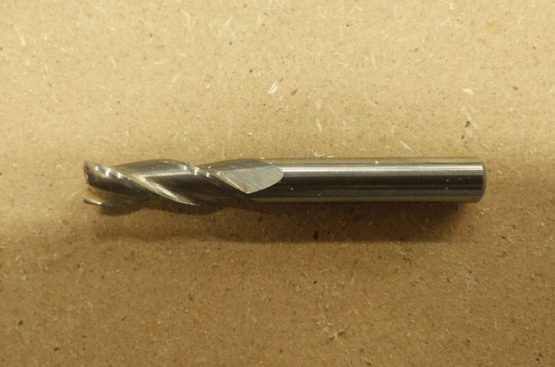
This is the 5mm squared-shaped end-mill I used
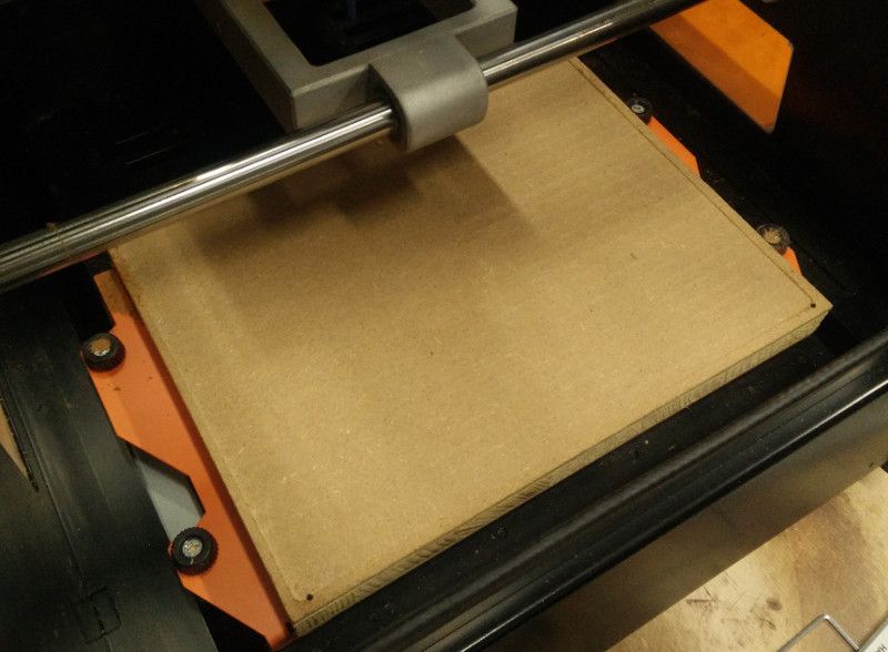
...and this is the final near-to-perfect result!
Here we come to PCB milling. A good online resource with a technical in-depth analysis about FabISP, leading to FabOptimus design, is article FabISP Demystified by MIT Media Lab Research Assistant Ali Shtarbanov; another interesting resource is FabISPKey design, where MIT Media Lab Research Assistant Andy Bardagjy points out FabISP genealogy before Neil's FabISP "hello.ISP.44" design:
- USB Tiny by Dick Streefland
- USBTinyISP by Limor Fried
- FabISP by David A.Mellis
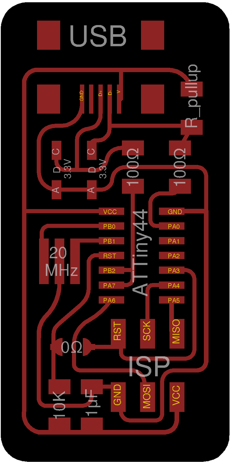
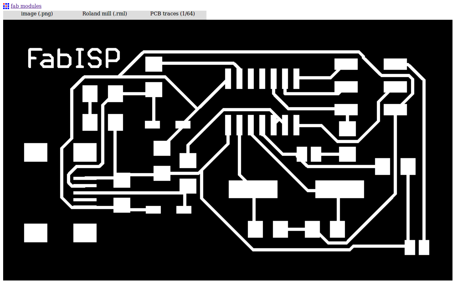
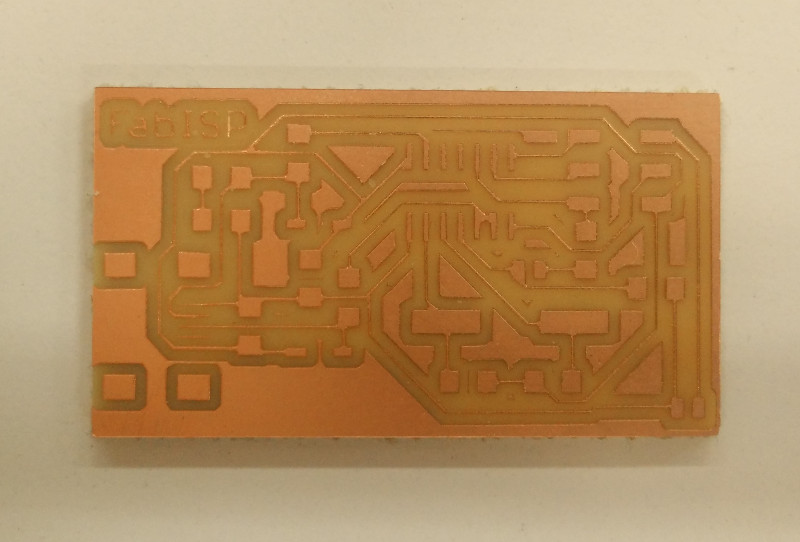
So, for the very first PCB milling attempt, I decided to stay classic and went for the original FabISP design by MIT Media Lab PhD David A.Mellis; David is also co-creator of open-source hardware and software platform for electronic prototyping Arduino.
First of all, I downloaded FabISP traces file
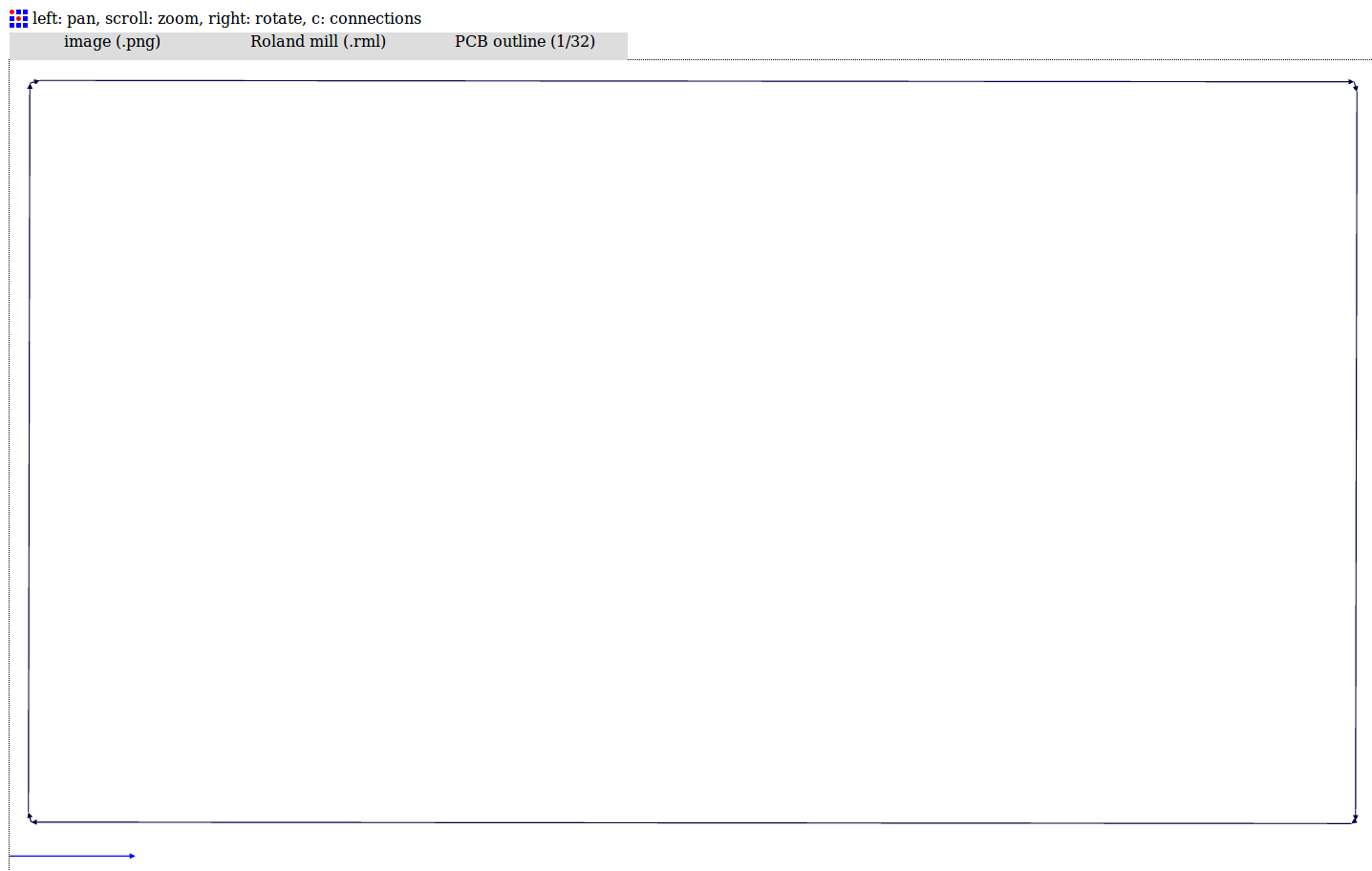
and the edges (to be cutted out) file

For creating the machine paths (CAM paths) this time I used the Fabmodules sofware (web version) and it's step-by-step procedure which supports very well the Roland SMR-20 precision milling machine. Fabmodules project is developed by MIT Centre for Bits and Atoms with the Fab Network and provides a set of software tools for personal fabrication, intended for use with machines common to fab labs; it includes:
- Tools to design 2D and 3D objects
- Functions to generate 2D and 3D toolpaths
- GUIs workflow from design files to machine commands
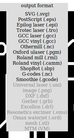
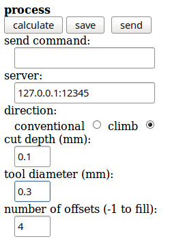
Selecting input file and parameters
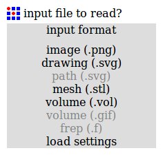
Setting output file and parameters
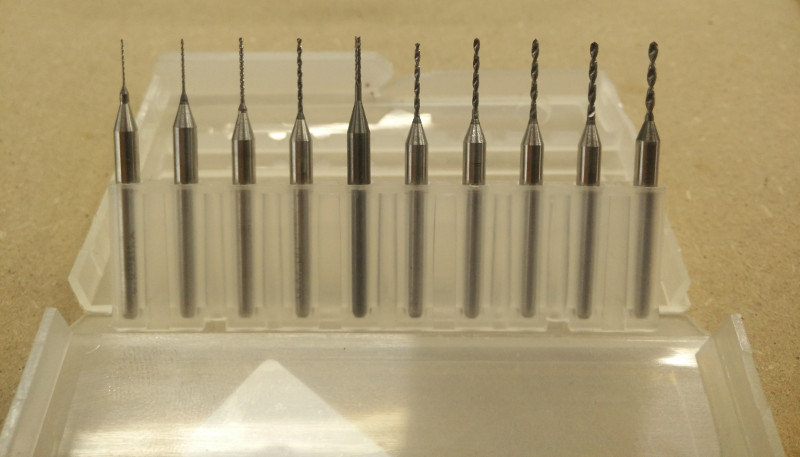
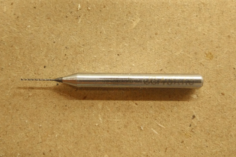
Picking different suitable endmills and defining for each of them the correct parameters (small note: as pointed out by guru instructor Bas Withagen during global review process, the ones portrayed in the following picture -except the darker one: position #5 from the left side- are NOT endmills but drill-bits and that's the reason why I experienced in fact also a pair of breakings; while a drill bit can only cut in the axial direction, a milling bit can generally cut in all directions, though some cannot cut axially)
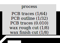
Selecting the process (PCB traces 1/64)
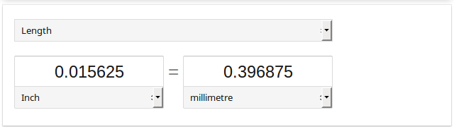
Calculating the exact inches => mm conversion (1/64 inches = 0.015 inches = 0.396 mm )
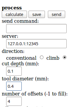
So, if a 1/64 inches "flat" squared-shaped endmill is chosen (this also got broken!)
tool diameter can be set to 0.40 mm
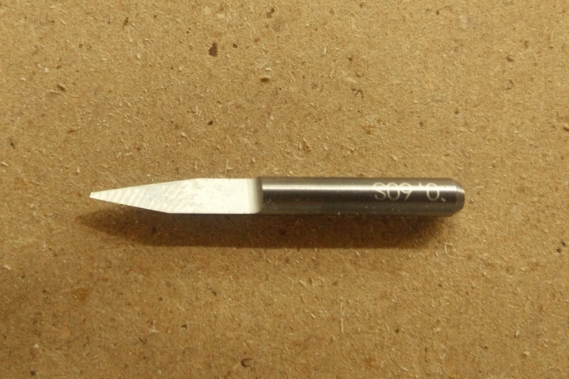
Since -as said before- I experienced lots of breakings and no stub-neck endmills were available in that moment together with Roland Monofab SMR-20 mill machine, I decided to try a V-shaped bit: this particular shape seemed to me less subject to breaking failures, at least at an absolute-beginner level; V-shaped bits however have a strong correlated issue to be aware of: variable thickness depending on depth of cut and V-angle, therefore making in some ways CAM process more "heuristic" and less "algorithmic". So, if a V-shaped endmill is chosen
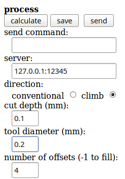
since tool diameter varies depending on milling depth and V-angle, it's necessary to estimate it; in this case 0.20mm it's been estimated
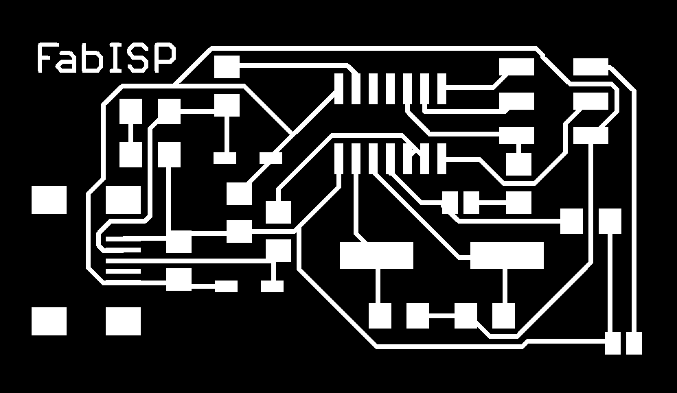
This is FabISP traces as seen inside Fabmodules
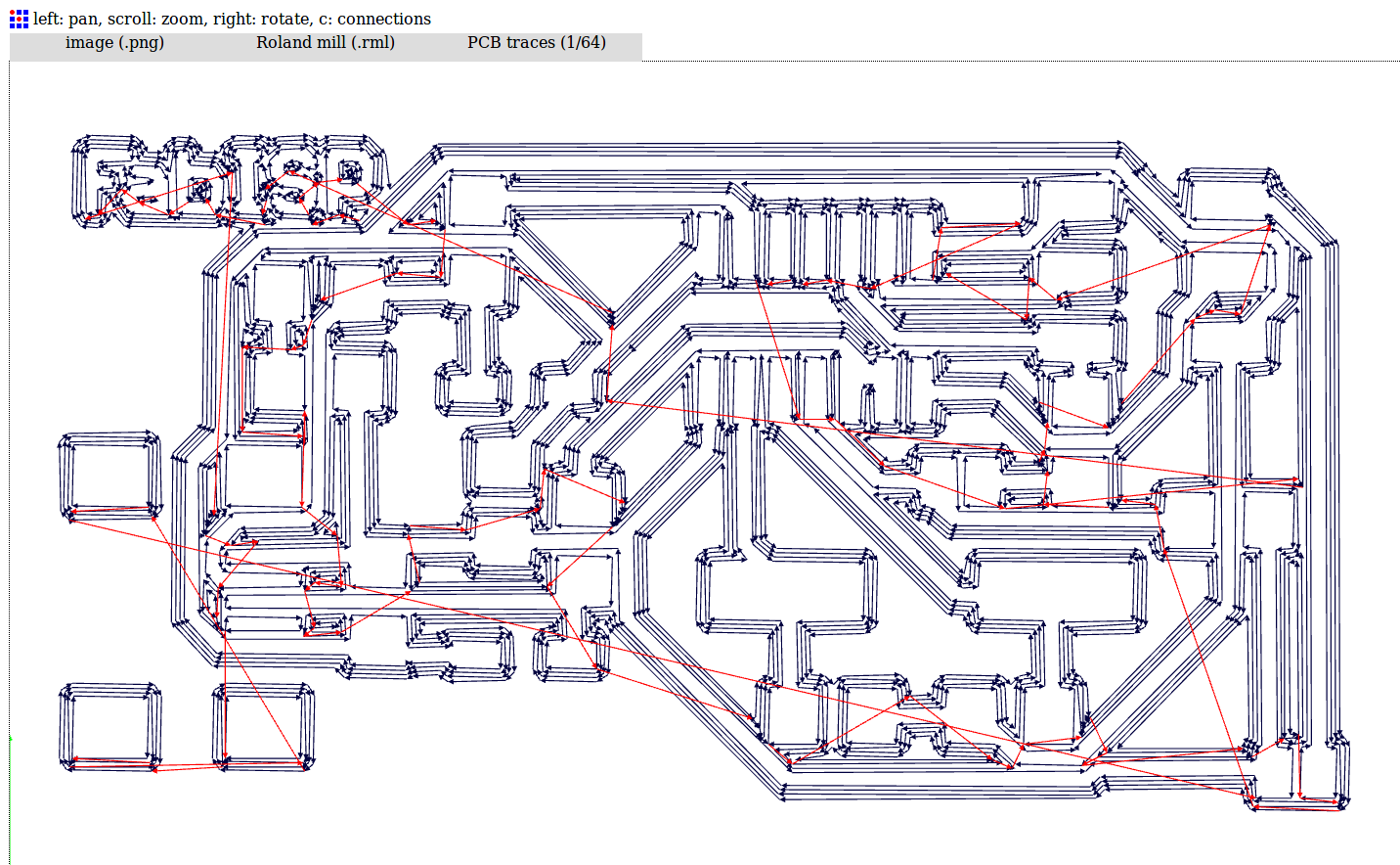
this is the tool-path
...and this is for the edges
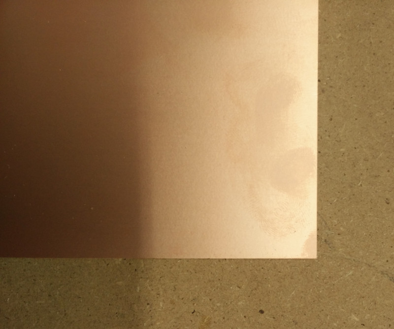
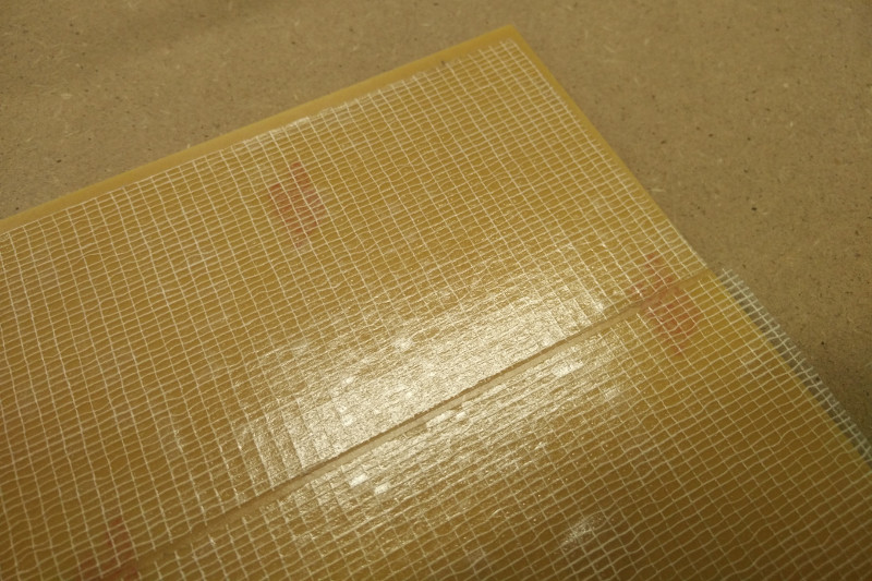
Sticking FR-1 (Paper Phenolic Copper Clad Laminate) sheets inside Roland SMR-20 precision milling machine
Fixing very tight with strong and thin bi-adhesive scrim tape
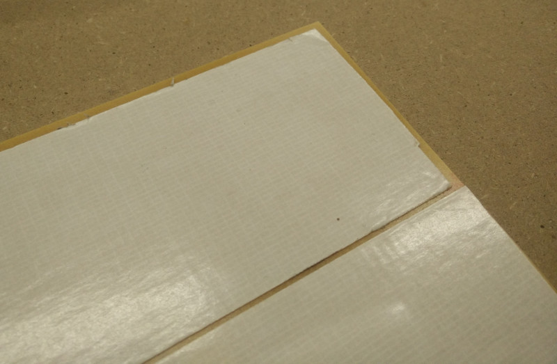
(peeling bi-adhesive top surface, at the very last minute)
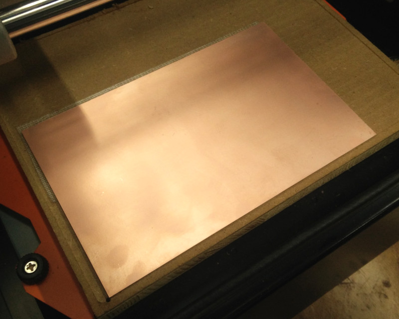
FR-1 sheet in place, ready to be milled
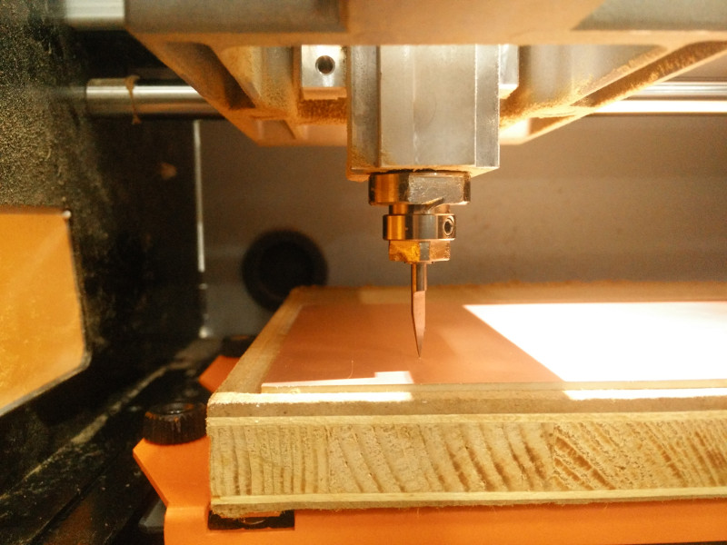
Bringing the endmill in the correct position (slightly touching FR-1 sheet surface)
Roland VPanel is the control software for Roland SMR-20 precision milling machine; it'is proprietary software from Roland DG Corporationrunning on Windows systems: I'm not super happy about this since, as far as I can, I prefer using Free Software and a GNU/Linux system
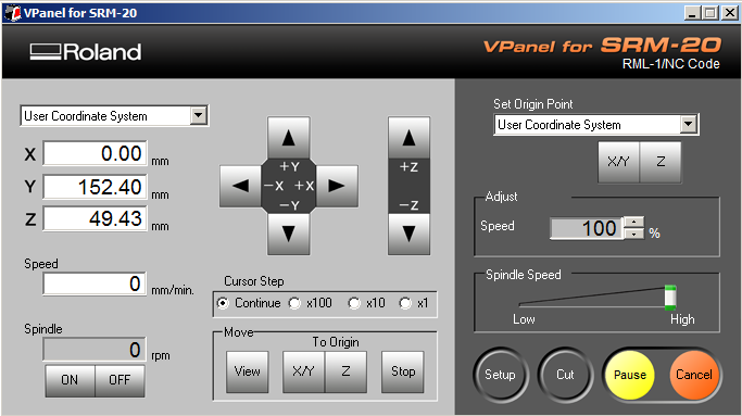
Setting Base ("Zero") Position on X and Y-axis

Setting Base ("Zero") Position on Z-axis

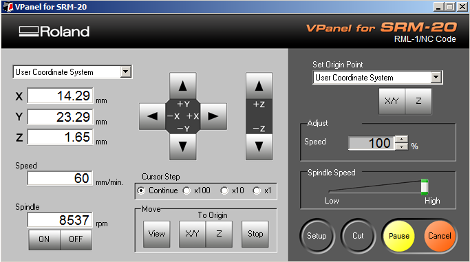
Starting with PCB milling (spindle rotation speed = 8537 RPM)
New tryout! Changing tool diameter from 0.20 mm to 0.30 mm -but again with the same V-shaped endmill
Evaluating the different results
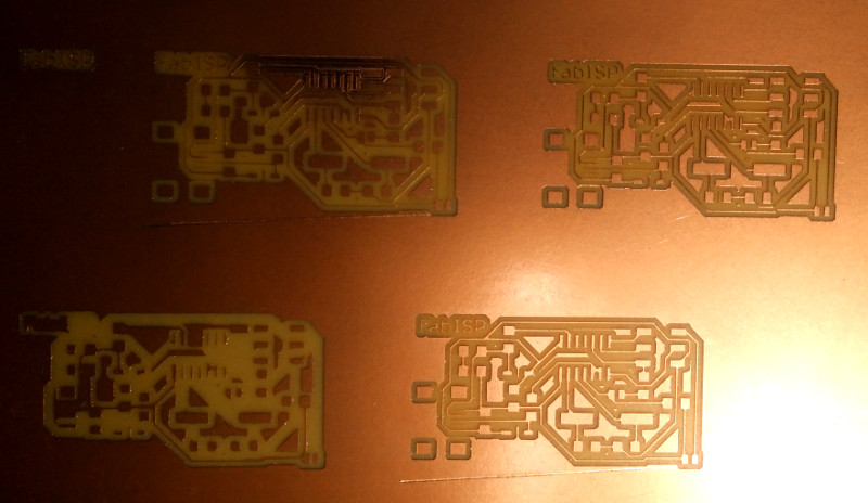
Can this possibily working fine? Let's make it the "solder-candidate", and cut-off edges! (0.80 mm endmill)

Now with a more finished look:
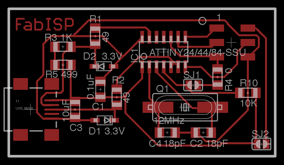
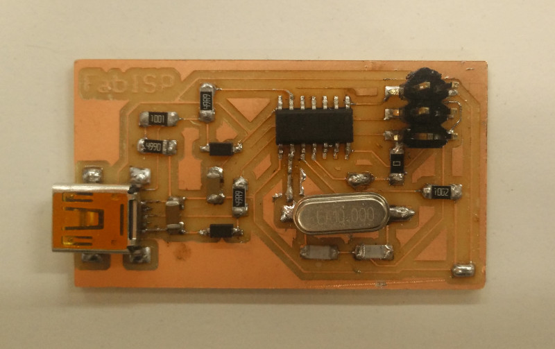
Time to solder! At this point, the freshly milled FabISP board needs to be stuffed with all the needed electronic SMD components (ATTiny 84-SSU, resistors, capacitors, zener diodes, crystal, headers, etc.), following the given schema. All over the Internet there's a lot of tutorials about PCB soldering, like the amazing Soldering is Easy comic for absolute beginners by american hacker and inventor Mitch Altman; there's also some good videotutorial about SMD components soldering, like the well-known Soldering Tutorial -Surface Mount by australian video-blogger David L.Jones; after retrieving this good information, I was ready to embrace the soldering iron and manually pick&place the components on the board surface one-by-one; indeed it was not so easy to me and required me more than one hour of time. Here's the "Hero Shot" with the final result:
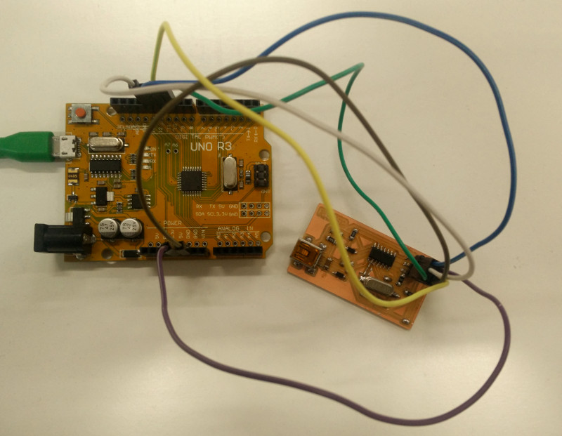
After completing the soldering of all the board SMD components, next step was board programming; not having another FabISP available, at first I decided to program it with an Arduino UNO-R3 clone board through the Arduino-as-an-AVR-ISP method and AVRdude software; however this failed: for some unknown reason AVRdude could not read the correct device signature from FabISP microcontroller ("ATTiny 84" signature)
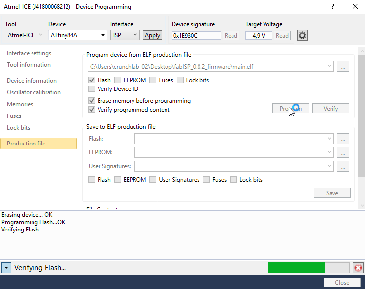
Not having enough time and experience to investigate in depth and figure out the reasons of the failure (at this point this could be an hardware -Arduino or FabISP- failure, or a software misconfiguration, or both), I decided to to program the FabISP in a more "traditional" way, using a commercial Atmel-ICE programmer (the one shown by Neil at the end of electronic-production lecture)
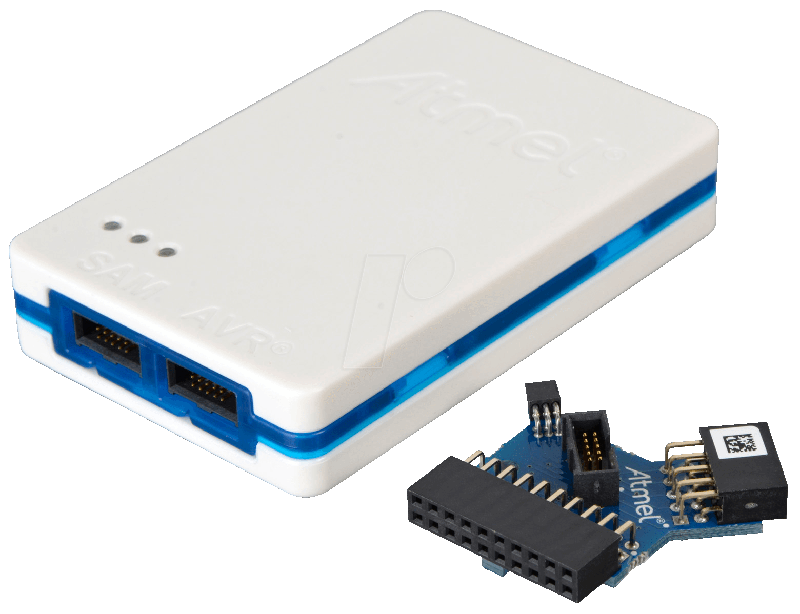
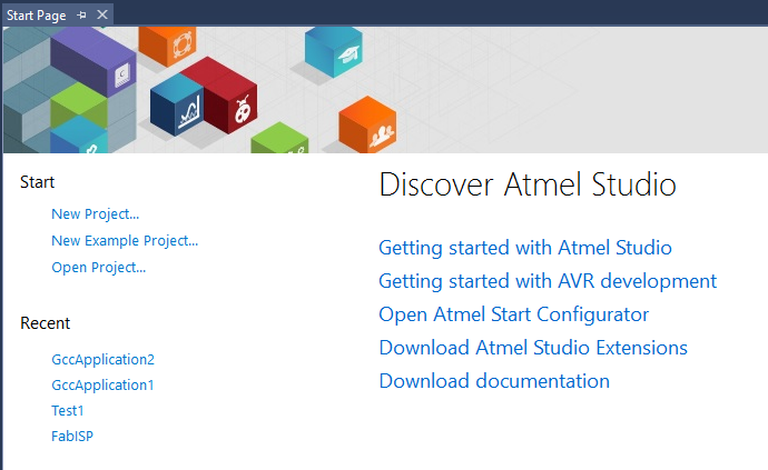
and Atmel Studio software; I was not super happy with it, since this is proprietary software only available over a Windows system and, as far as I can, I prefer using Free Software -however, it worked like a charm! :)
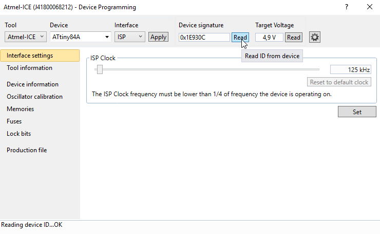
after connecting ATmel-ICE to FabISP (and both to computer USB) it was possible to configure Tool, Device, Interface; and reading FabISP voltage and signature (...this time signature was correct!)
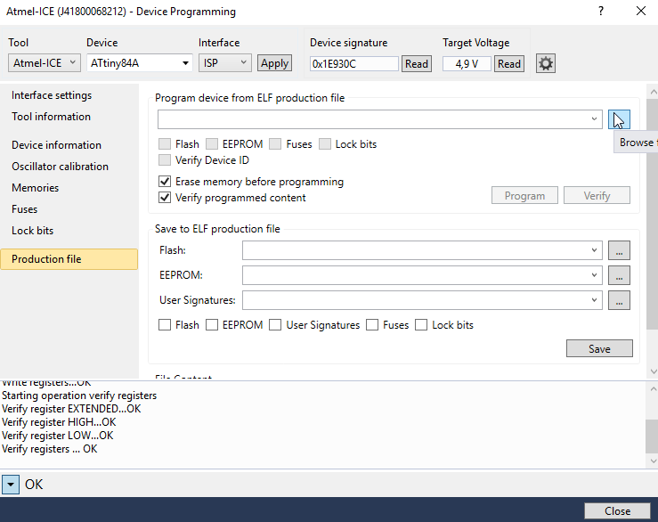
then selecting the correct .elf file firmware (the one given by Neil during the electronic-production lecture)
and flashing it to the FabISP
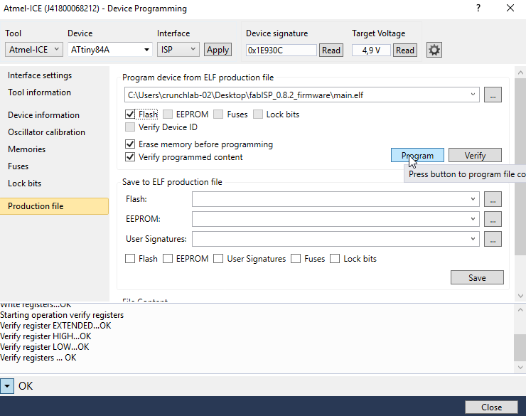
(...flashing in progress...) / 1
(...flashing in progress...) / 2
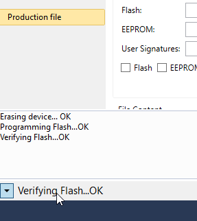
...FabISP programming done!
Source files
- fabisp.traces.rml -Fabmodules output RML File (Traces)
- fabisp.edge.rml -Fabmodules output RML File (Edge)