Ruby Sun
Fab academy 2017
Week 10: Output device
Learning outcomes
A. Using Eagle to design the board
B. Milling the design board
C. Soldering
D. Programming
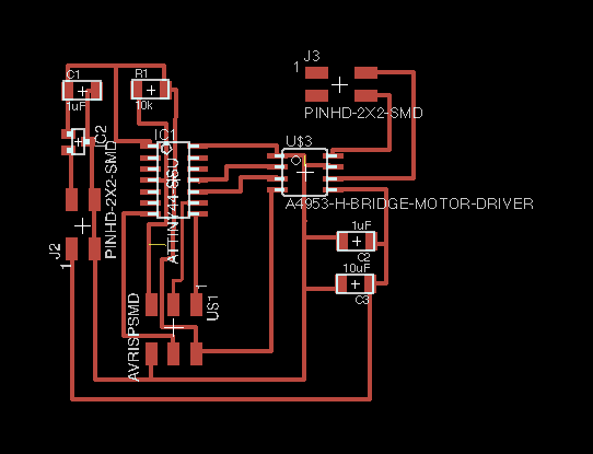
A. Using the Eagle to design the board
The process of using the Eagle would be the same as the electronic design before.
At the end, a schematic diagram which shows the circuit is drawn.

Through the two buttons below, a schematic view is switched to the board view.
The process afterward for choosing the top four color foBy clicking the multiple color button, we can choose the top four color for display.
Type 'drc' for opening. Go to clearance and change all the values to 16mil.
After checking in drc, it appears a list of items that i need to remove. I have to pay special attention for the 'clearance' alerts.
After removing all the errors, then export the board as a png (file --export--image). The setting is set for Monochrome and 500 dpi for resolution. Drag the png file to the photoshop and set the canvas image with 20px more for the height, as well as for the width.
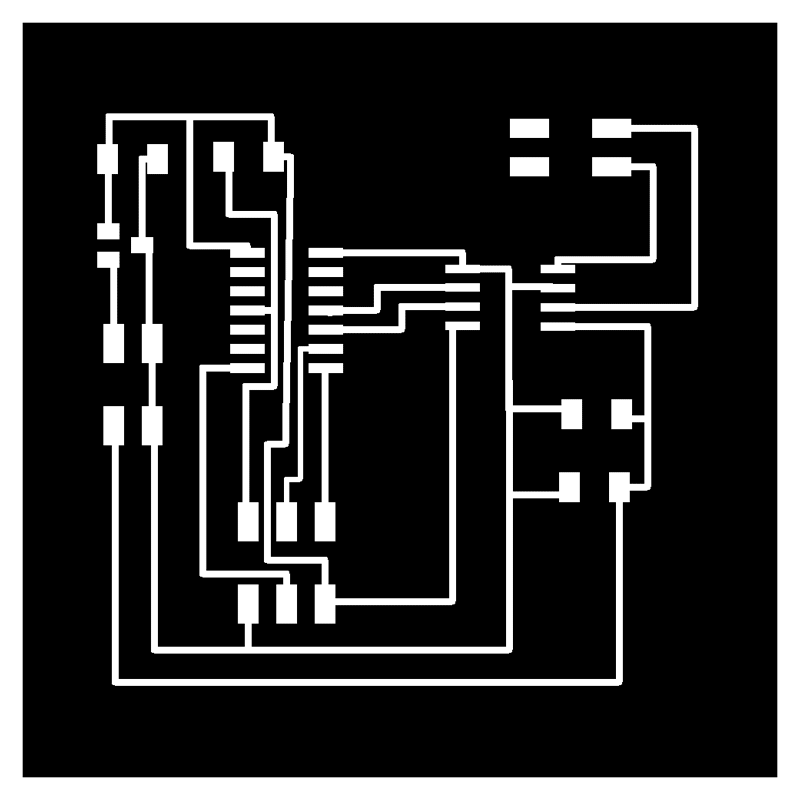
For the second layer, create the layer with black boarder and white interior.

After producing the file, it is ready to be milled using the Roland Mill under the setting as follow (fabmodules.org).
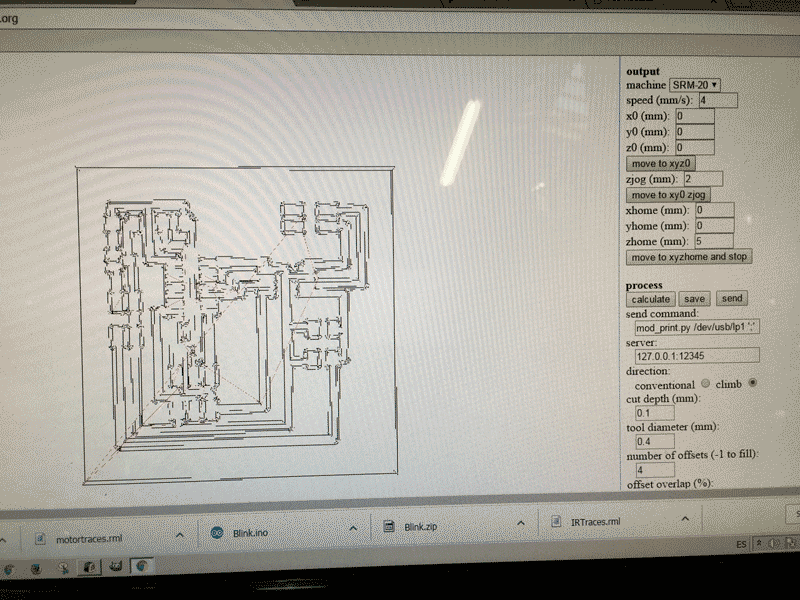
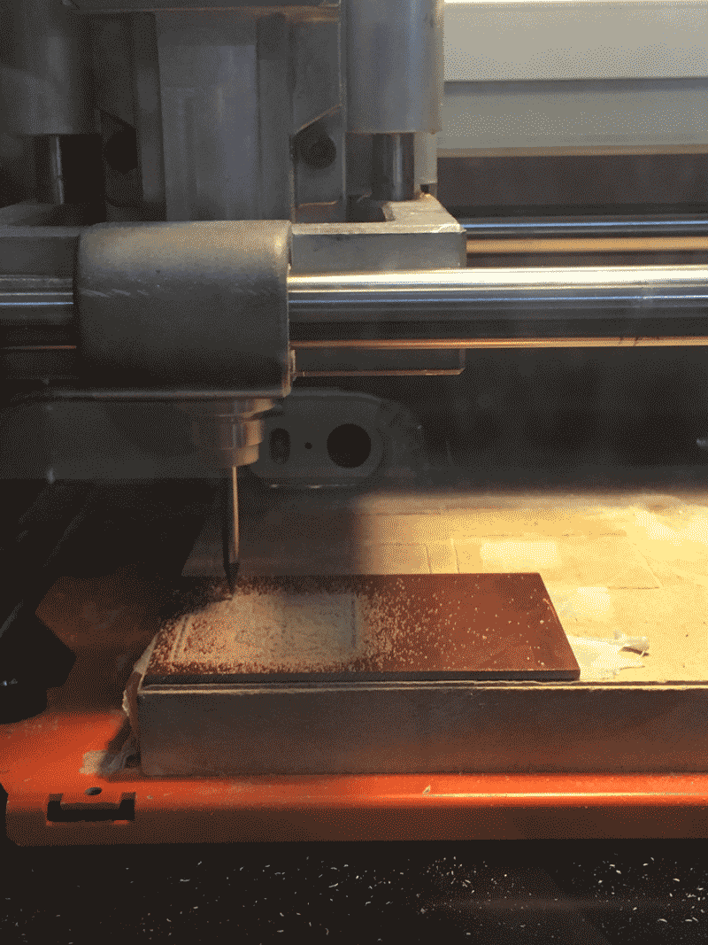
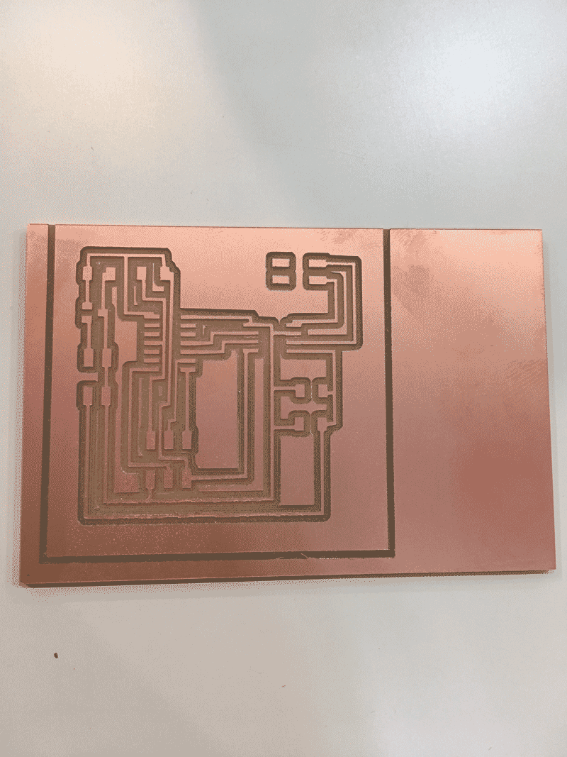
After preparing the traces of the circuit, repeat the same procedure for the outline, the only difference is to choose 'PCB outline(1/32)' instead of 'PCB traces (1/64)'. After preparing both files (.rml), i start milling by using the Roland mill.
Press 'X/Y'for moving the milling tools to the corner of the material, use 'Z'for adjusting the height of the tool to make it nearly touch the material. After adjustment, press 'X/Y' and 'Z' which are under the 'To Origin' section for setting the origin.
After all the setting, press 'cut' and add the file that i want to print.
B. Soldering
After milling my board, I started to collect all the needed components for the board and here is the list.
1. Attiny44
2. Resistor 10k
3. 2 Capacitor 1uF
4. Capacitor 10uF
5. IC regulator
6. 2 J 2x02SMD
7. AVRISPSND
8. IC3 A4953
Solder all these components.Pay attention for soldering some of the items, for example the direction of IC3 A4953.
Below is the finished board.
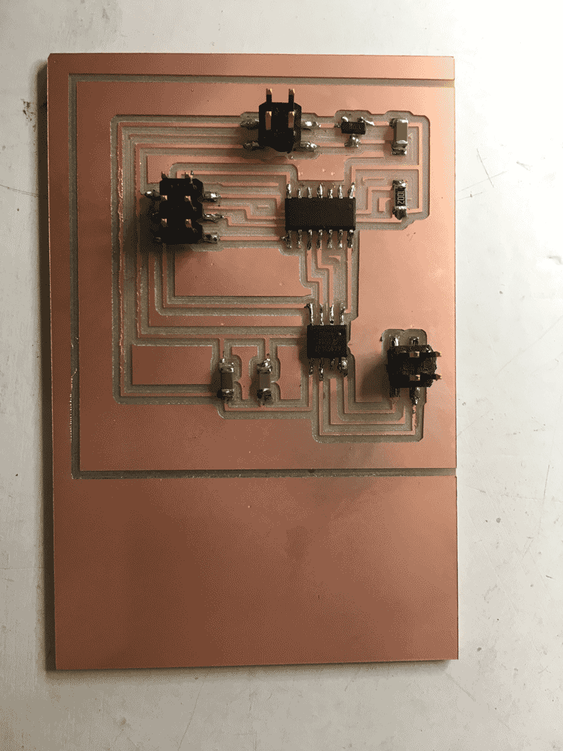
After finishing the board, i discoved that one of the leg of the IC3 A4953 is not properly soldered and i missed the connection of the Voltage of J2 power. Therefore, i soldered the two points with a wire for connection afterwards.
C. Programming
After finishing the board, then i programmed the board. At first i try to progammed through the C file.
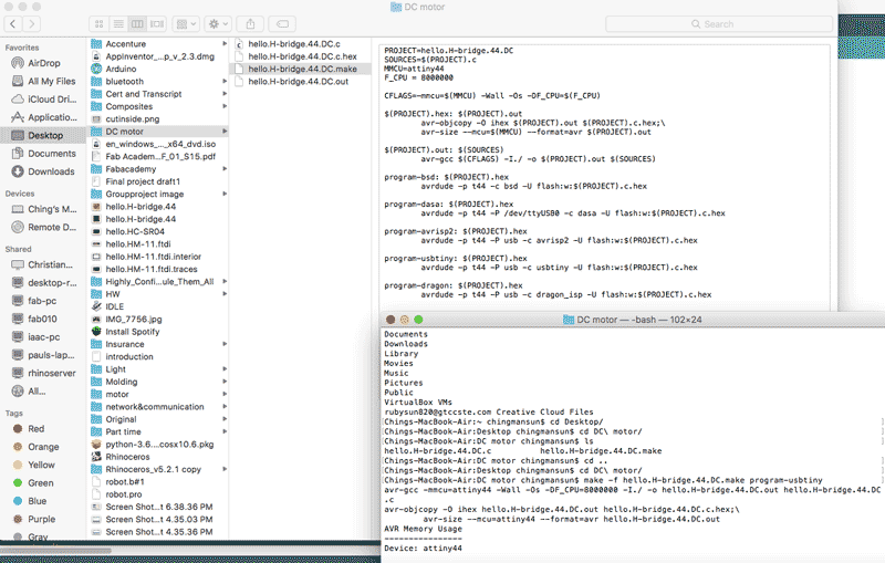
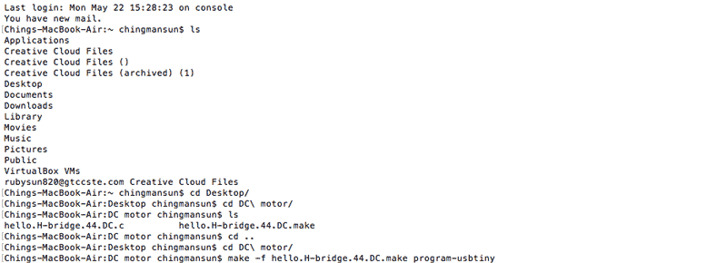
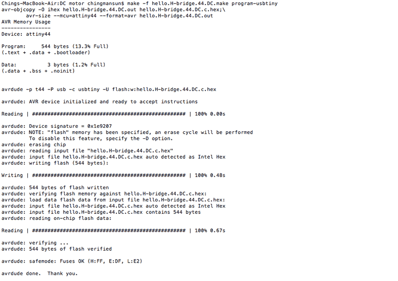
However, after the programming the motor does not really move. Therefore i tried to program through the arduino as follow.
Firstly, open the 'File', then to 'Examples', 'Basic' and choose 'Blink'.
1. Change 'LED_BUILTIN' to 2 (Because from the design of the board, the LED is connected to pin 2 of the arduino and can take reference from Week 8for the pinout of Attiny 44.
2. Add (int i=0; i<5000;i++) after the bracket of the loop.
3. Delete the first delay(1000) and change to 2000 for the second delay. (this is for controlling the time in milisecond)
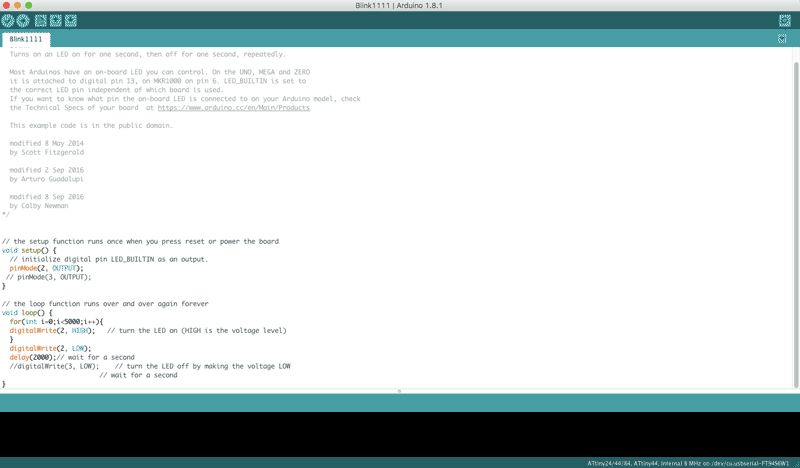
The motor moves after programming through the arduino.
Please press the link for downloading.