Fab academy 2017
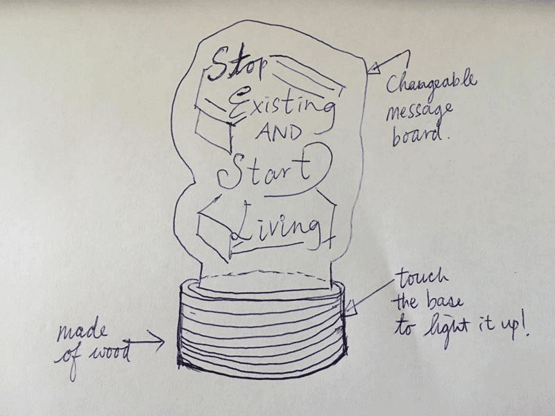
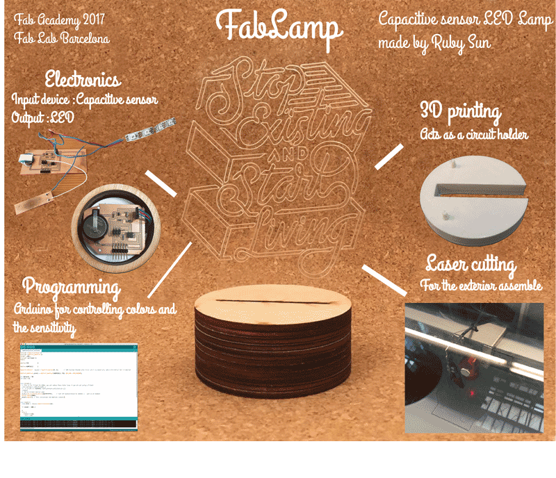
I have always wanted to make a lamp with some personal touches. The lamps sold in the market are mostly fixed and cannot add messages on the lamp. Therefore, the idea of making a customizable lamp which is easily affordable has come up.
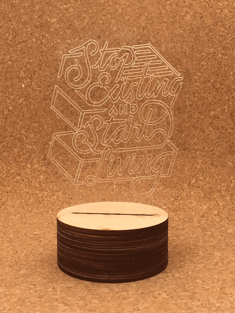
Lighting up a meangingful message in the form of calligraphy is the primany goal of the project. Using easily accessible material, such as wood and acrylic so that everyone can make it with affortable cost.
LED Strips - 0.45 euro for 2 pieces of LED
Supply Voltage (3V Lithium Battery x 5) - 3 euros
Battery holder - 1 euro
Attiny 45 - 0.88 euro
Copper Capacitors - around 0.2 euro for a small piece
AVRISPSMD - 0.91 euros
Regulator 5V 0.1A - 0.35 euros
Capacitor 1000uf - 0.09 euros
Capacitor 1uf - 0.09 euros
Six-pin header - 0.83 euros
Resistor 1M ohm - 0.09 euros
Resistor 470 ohm - 0.09 euros
Three-pin header - 0.83 euros
Plywood birch - 12.71 euros
Acrylic glass - 5.45 euros
The total cost would be around 26.97 euros.
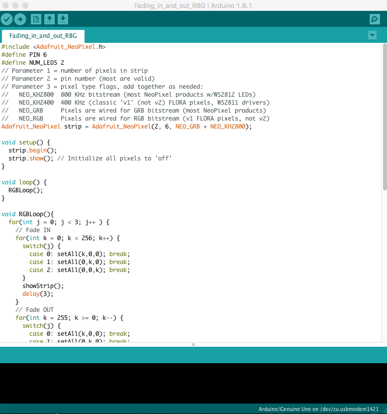
1) Firstly, I started with trying different codes for controlling the effect of LED. The following is the setting of the LED strips.
There are three pins with the LED.
- GND of LED to the GND of ardunio
- DI of LED to pin 6 ardunio
- 5V of LED to 5V of ardunio

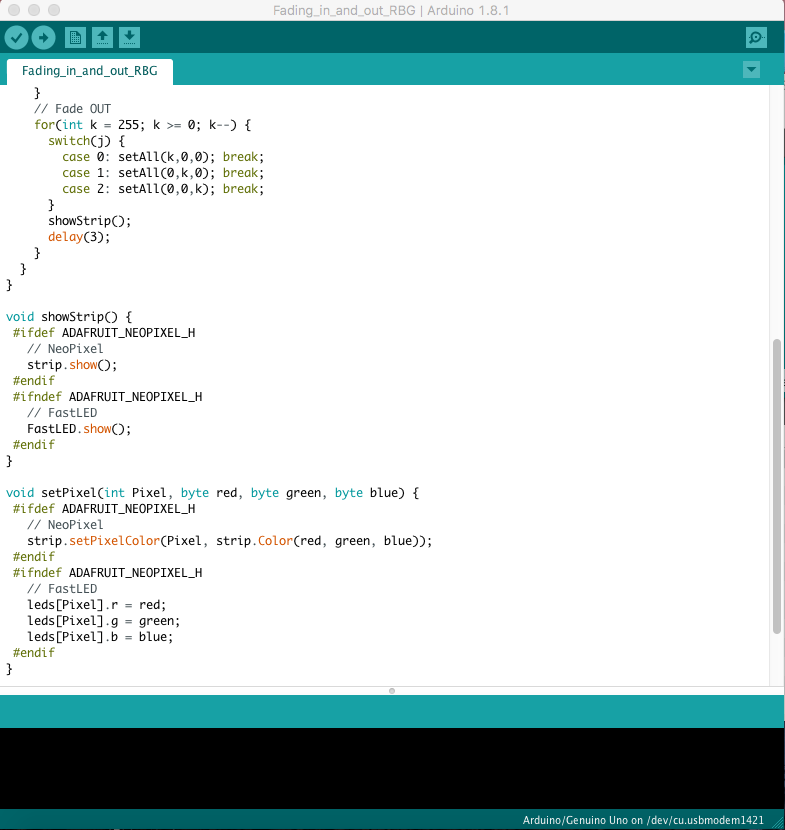
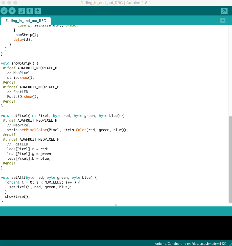
Below are the codes for having the rainbow effect of fade in and out.
Below shows the effect of the LED.
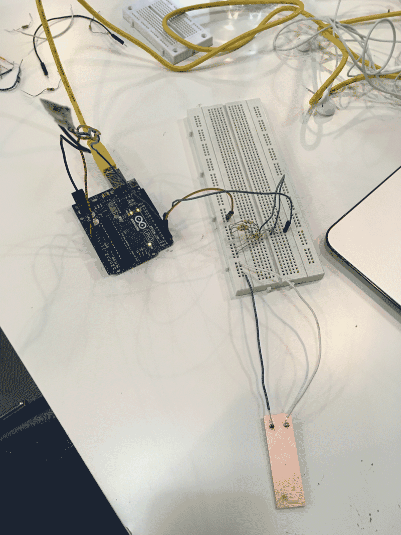
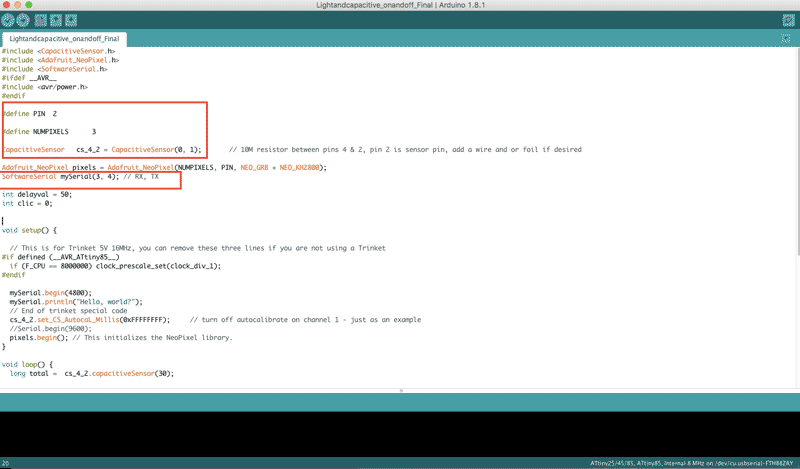
2) Secondly, I tried with the Capacitive sensor. Below is the setting of the Capactive sensor.I just grab any copper plate that is avaliable then solder one/two wires on the plate. Use 10Mohm for the resistor in between. Connect the 'send' which is the red wire to pin 2, while connect the 'receive' which is green wire to pin 4.
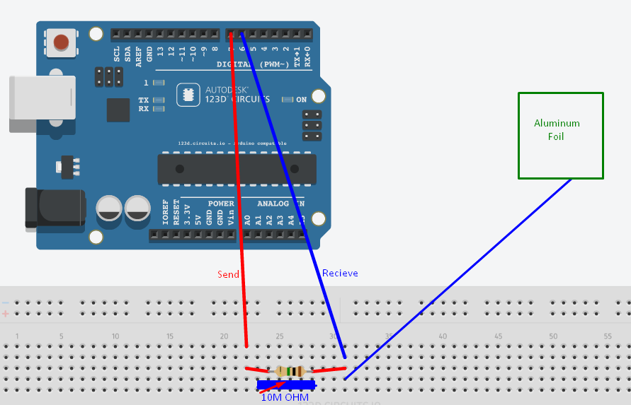
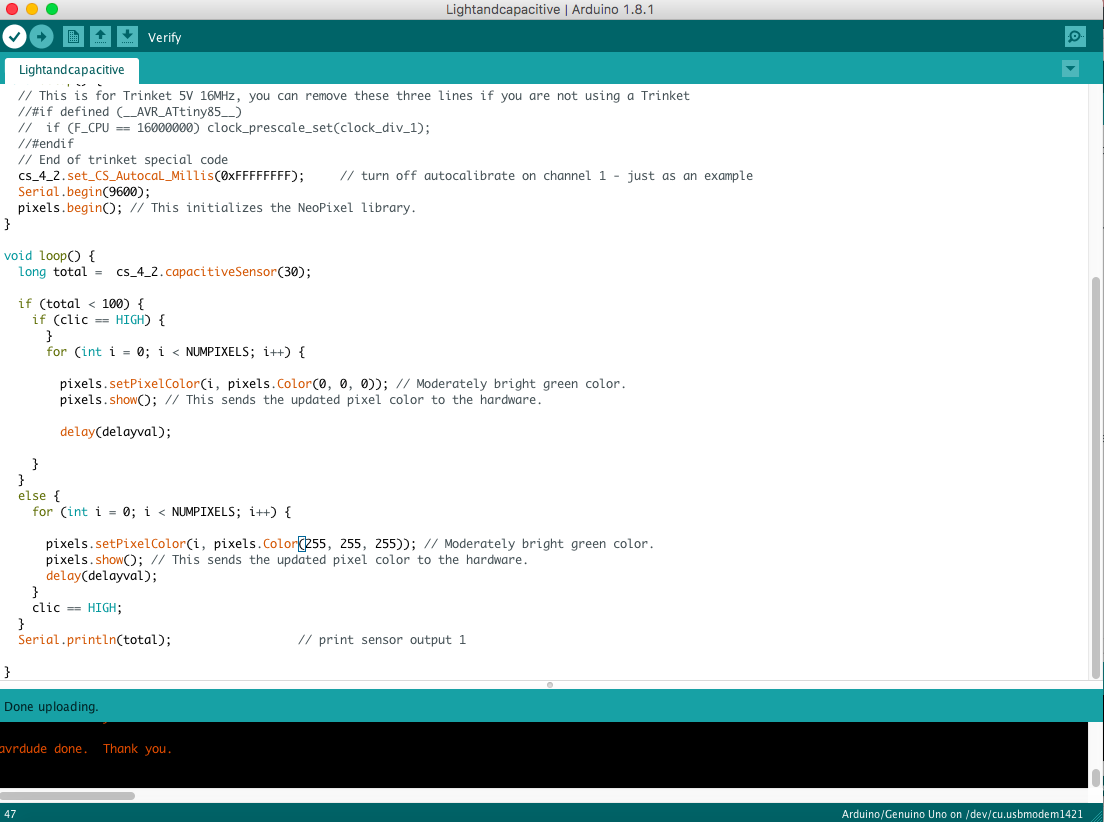
Below is the code for controlling the capacitive sensor.

When everything is set, the senial monitor will show the changes in number. When I press the copper plate, the number will increase quickly. Below it shows the effect of the capacitive senor.
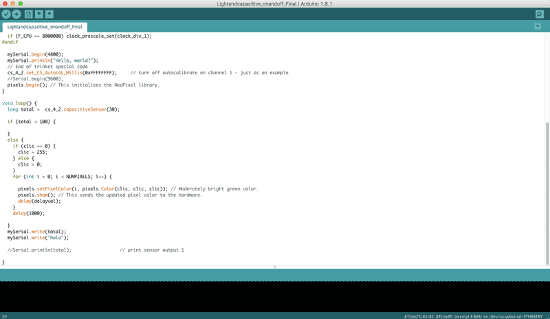
3) After making the LED code and Capacitive sensor code work separately, it is time to combine them together!

Below is the code with combine the led and capacitive sensor together.

After the set up, when you press the copper plate, the light will turn on.
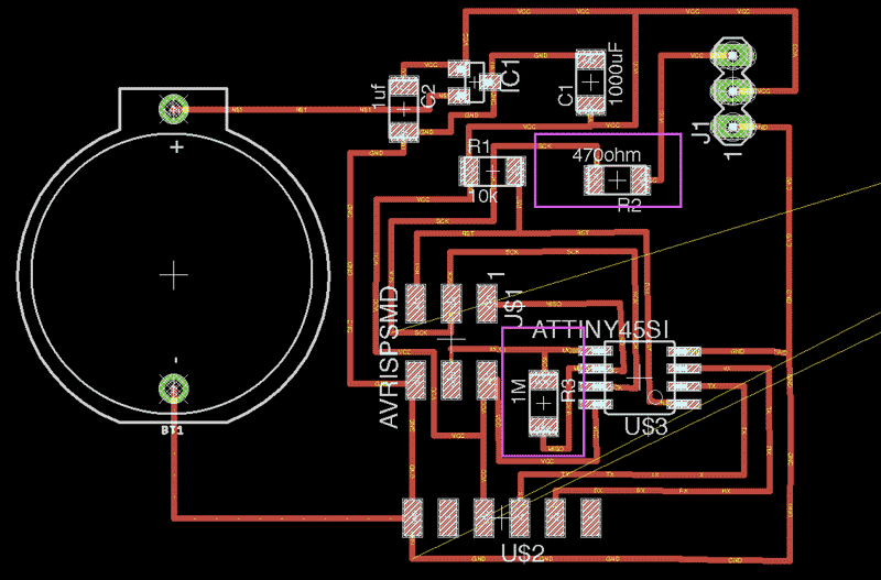
4) When the testing with the arduino is good, the next step would be to draw the circuit in Eagle.
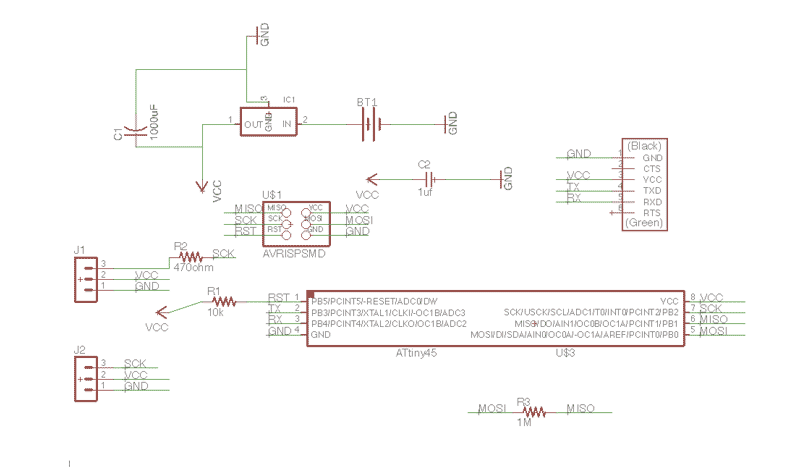
Here is the list of components:
1) Attiny 85
2) AVRISPSMD
3) Regulator 5V 0.1A
4) Capacitor 1000uf
5) Capacitor 1uf
6) Six-pin header
7) One battery holder
8) Resistor 1M ohm
9) Resistor 470 ohm
10) Three-pin header
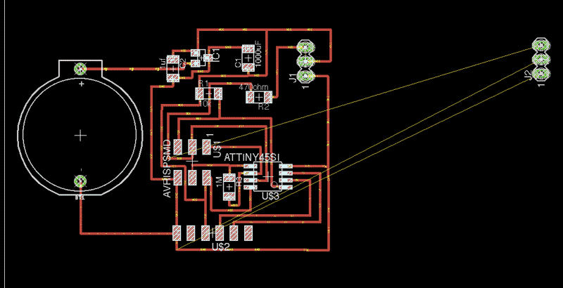
In the schematics, the resistors of 1M ohm is connected between the MOSI and MISO.That is for the connection of the capacitive sensor. While the LED strip will be connected to the SCK of the AVRISPSMD through the Resistor of 470 ohm. They are indicated in pink.
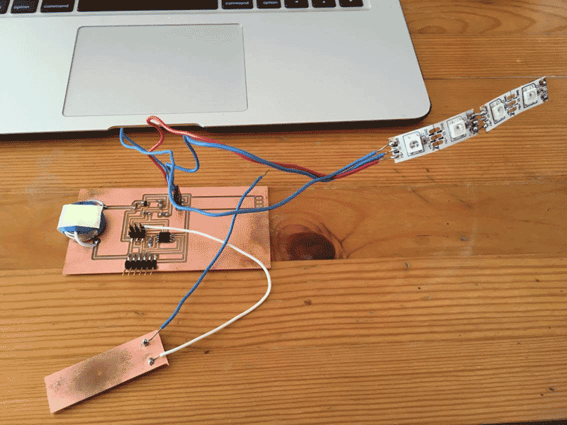
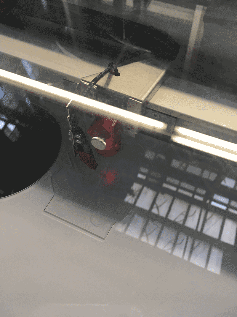
After completing the circuit, here comes the milling, soldering parts. At first, When I connect everything with one battery, I try to turn on the light and it only show the color red. The reason is because of the battery voltage is only 3V, while the LED strip needs 5V. Therefore two batteries are connected in a pack to provide 6V for powering the LED. Finally, the LED light shows the color of white.
5) After making the board, the coding will have to adjust as the pin number of the arduino is different from the connection in the circuit board and here is the Attiny 85 pinout.
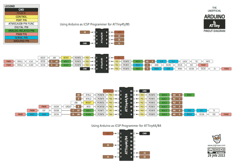
For example, for the Attiny 85, i connect the LED with the SCK, therefore its pin 2. For the capacitive sensor, as it is connected with MOSI and MiSO, so that is pin 0, 1. For the TX and RX, since the pin is 2,3, therefore it's pin 3,4 for the coding.
Below shows how the capacitive sensor works with the LED strip.
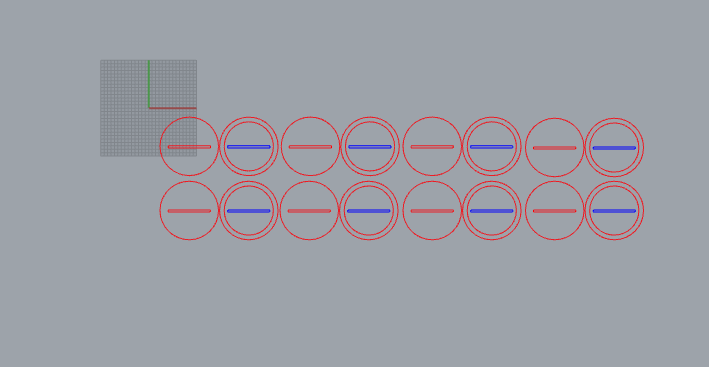

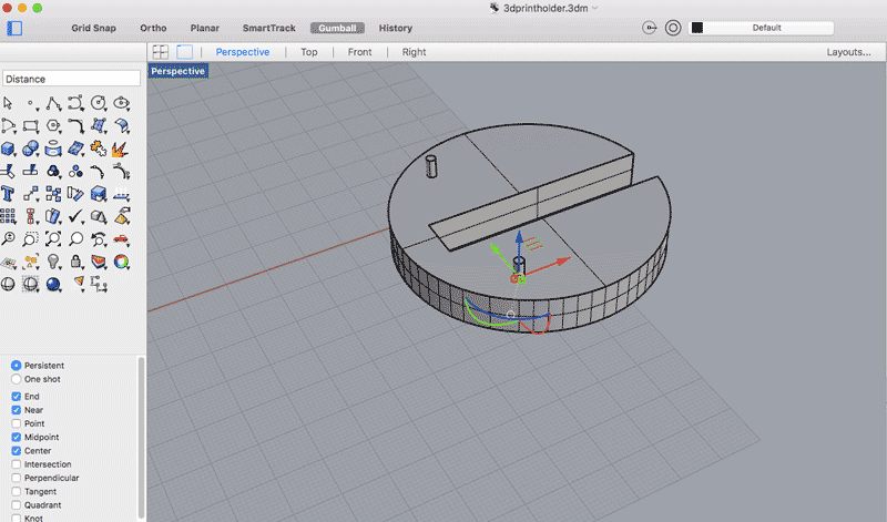
After using the Rhino for the drawing, then the file will be sent for laser cutting.
Below is the finished product after the laser cutting, then i will do the sanding of the wooden edge.
Download for programming files
Download for eletronics files
Download for design files