In the interests of survival, we opted to put aside our modular design in the interest of time and workability. Instead, what we did was resize our machine so that the work area is 610 x 625 mm, which we measured to be a good scalable size using the standard 2500x1220 plywood sheet.
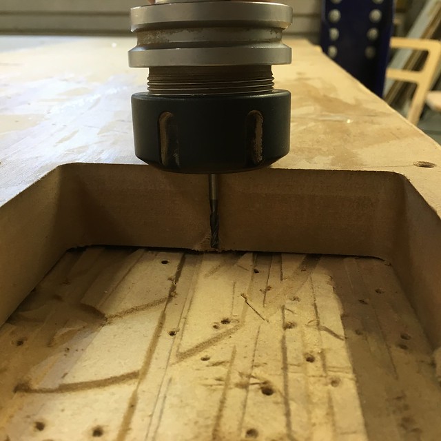
To get our base frame right, we decided to use some discarded MDF wood, this time with close attention to align the drill holes so as to make sure the rails would be perfectly parallel. The MDF measured just over 30mm in thickness which meant readjusting the 3mm bit to drill screw holes through the material.
This done, it was smooth sailing until the outer profiling. Here we forgot to readjust the 6mm mill bit for the same cut depth and were forced to stop the machine on its third run as the mill head began chafing the top of the material! Woops. Amends made, we got our base and frame milled without further hitches.
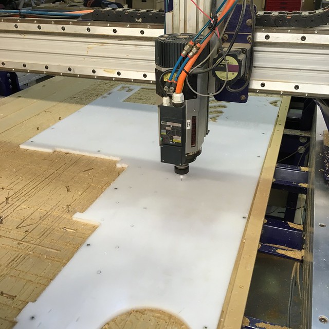
With a lovely piece of HDPE at our disposal we set about milling our machine X and Y rails, as well as side blocks and miscellaneous other machine pieces. This required a complicated design nesting and milling strategy. Besides, we were using a riddled and unsymmetrical, hard plastic material for the first time; as well as 3 different tool bits (3mm, 6mm and a 60 degree chamfer bit). It didn’t help that it was Friday and everyone was on weekend mode already.
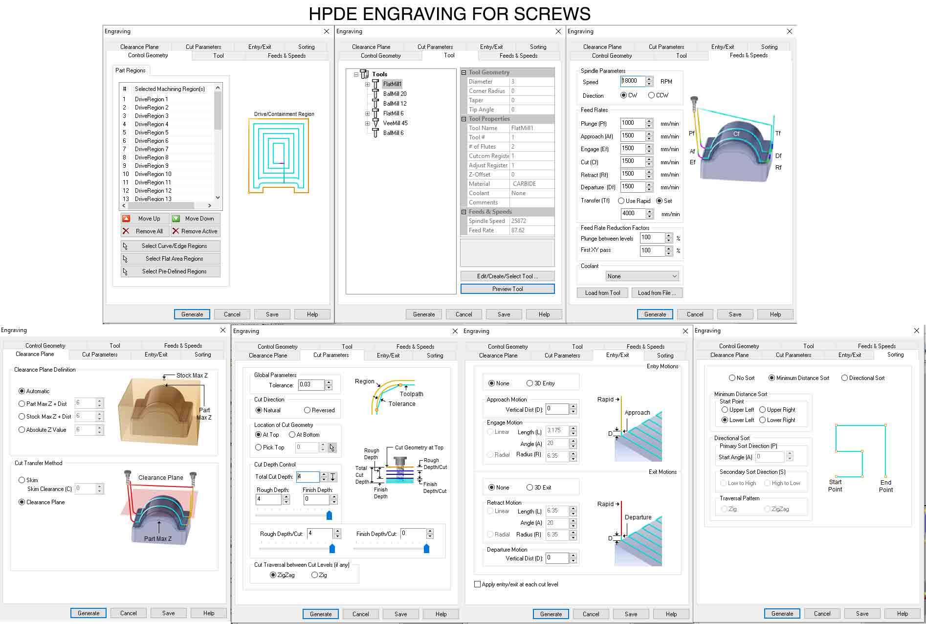
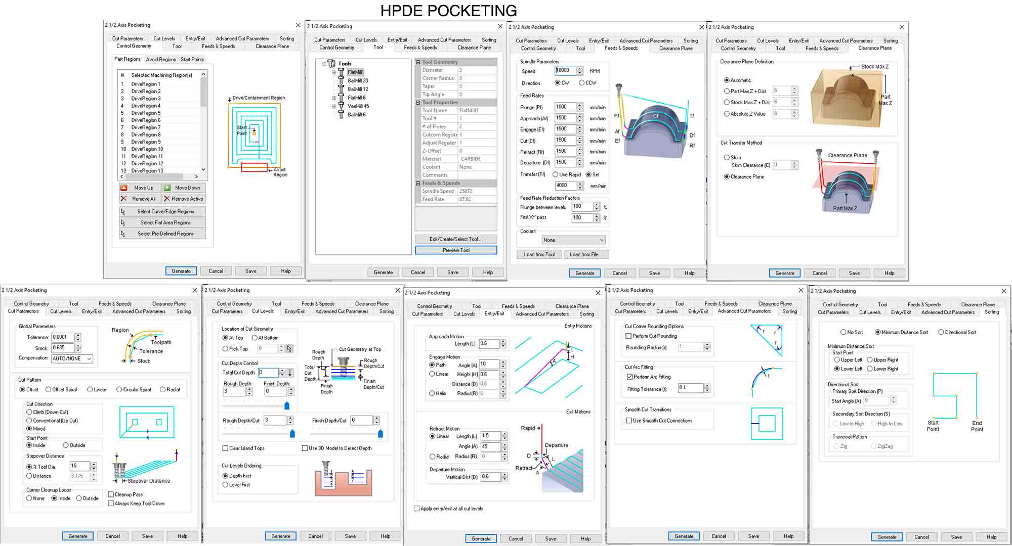
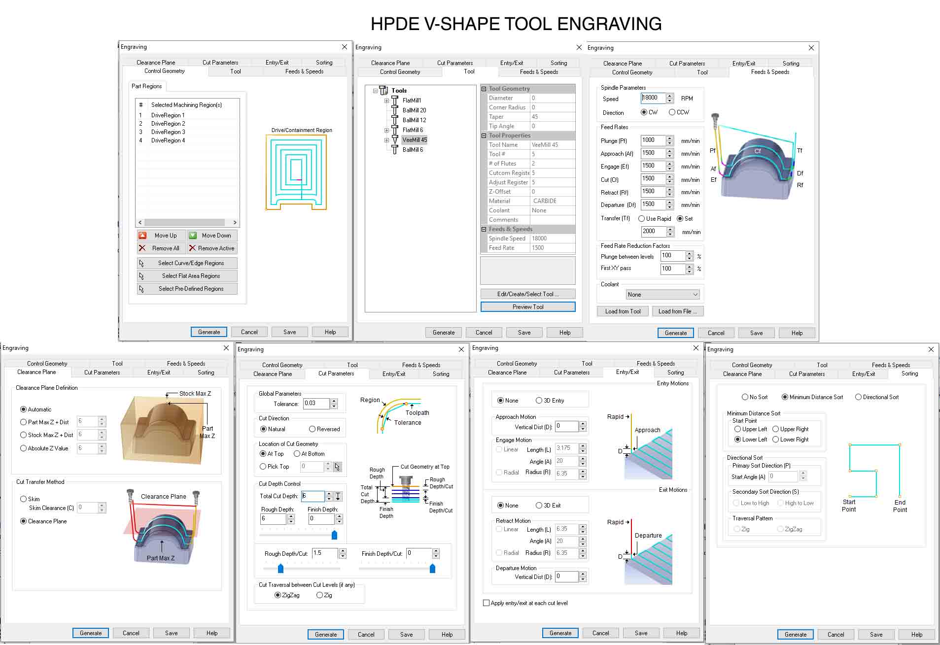
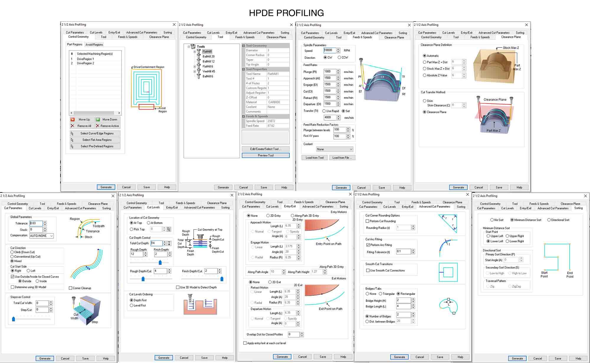
Thanks to Julia’s meticulous nesting and Rhino CAM skills we managed a good half way through the job, managing the more complex chamfer and 3mm rail part of the milling. The tricky part was getting the correct feed rate and spindle speed for each mill bit. For the 3mm and 60 deg chamfer it was important to stick to above 12,000 rpm or we would risk breaking the bit on the dense material. This are the CAM we used for the aterial. IWe had to check out the feedrates and speeds with our project manager as it was a material no one of us have ever used. This are Cams
For the chamfer, we set a 2mm plunge depth which meant that the bit went down 2mm at a time on 3 passes, going deeper each one to eventually create our desired 6mm deep angle. Ideally, with this sort of bit we learned it is best practice to create an incremental plunge depth as the deeper it goes the more resistance it creates. At least the bit didn’t come flying off and kill one of us as we were warned could happen so we live and learn.
Assembling our parts we ran in to some problems, always aligning the frame bed and Y rail. Making sure the drill holes in the frame elevation are perfectly parallel is really important at this stage. This will ensure the rails are aligned. Because we were stacking 3 bits of MDF on top of each other for elevation, doing this even using hand-held guides and balance tools is never going to be perfect, and in the end we had a 1mm difference between opposite sides of our board.
Next time we think it would be prudent to machine our drill holes once the frame and elevation is already mounted.
Also, the little detail of knowing which kind and size screws to use is important before milling. We were left imporvising a little once we had all our parts milled, and ended up using nuts and bolts that extruded too far off the Y plate, meaning we had to elevate the X plate using lasercut pieces.
Finally, this prototype was intereseting because it showed us the strength and tolerance of the HDPE material. What we found was that the X rail and foundation tended to sag under the motor weight, making us resort to a piece of aluminium for the foundation support. This wasn't too hart to fix but again aligning everything so that it doesn't interfere with our fitted parts was paramount.
Again due to time considerations and the complexity of the asignment and machine, we decided to leave aside the Z axis for when the masked avenger returns. With more time, we would like to build on this prototype to get a working Z axis milling machine, but for now we decided to concentrate on getting our linear axis X/Y working first.