Week7 : Embedded Programming
AVR getting started
I plunged in the AVR world headfirst. I decided to spend some time to find a way around the Arduino IDE, or basically something that replaces the straight forward IDE. There are many resources in the net about this topic. I haved worked in C/C++ previously so I expected to find my way easily in the avr-libc. But I was not totally correct with this assumption. Neither a knowlege with the Arduino programming using the much intuitive IDE would help, simply there remains a low level element in avr-programming that you have to take care off or atleast understand.
The following was a very useful for linux users to start with avr-programming:
http://www.swharden.com/blog/2013-01-06-avr-programming-in-linux/
The first step on ubunut was to set the tool chain
sudo apt-get install gcc-avr avr-libc uisp avrdude
Testing the tool chain on an Arduino Board
I used avr-gcc to compile a simple blink-c-code script written in c and using the avr-libc library. I thought since I will repeat those steps many times for every example c program, created a simple bash file to be able to do the whole compilation process of creating an object file, a hex file and uploading it to the avr in one command line.
sh test.sh obj_filename c-code_filename avr_chip Port


#!/bin/bash

// Compile the code and generate HEX file

//for attiny with 20Mhz external resonator
avr-gcc -w -Os -DF_CPU=20000000UL -mmcu=$3 -c -o $2.o $1.c
//for arduino uno
avr-gcc -w -Os -DF_CPU=16000000UL -mmcu=$3 -c -o $2.o $1.c


avr-gcc -mmcu=$3 $2.o -o $2

avr-objcopy -O ihex -R .eeprom $2 $2.hex

// Set permission for the selected port as read write for all users

sudo chmod a+rw /dev/tty$4

// Program the HEX file onto the avr_chip

avrdude -F -V -c arduino -p ATMEGA328P -P /dev/tty$4 -b 115200 -U flash:w:$2.hex
USBtiny issues and Debugging
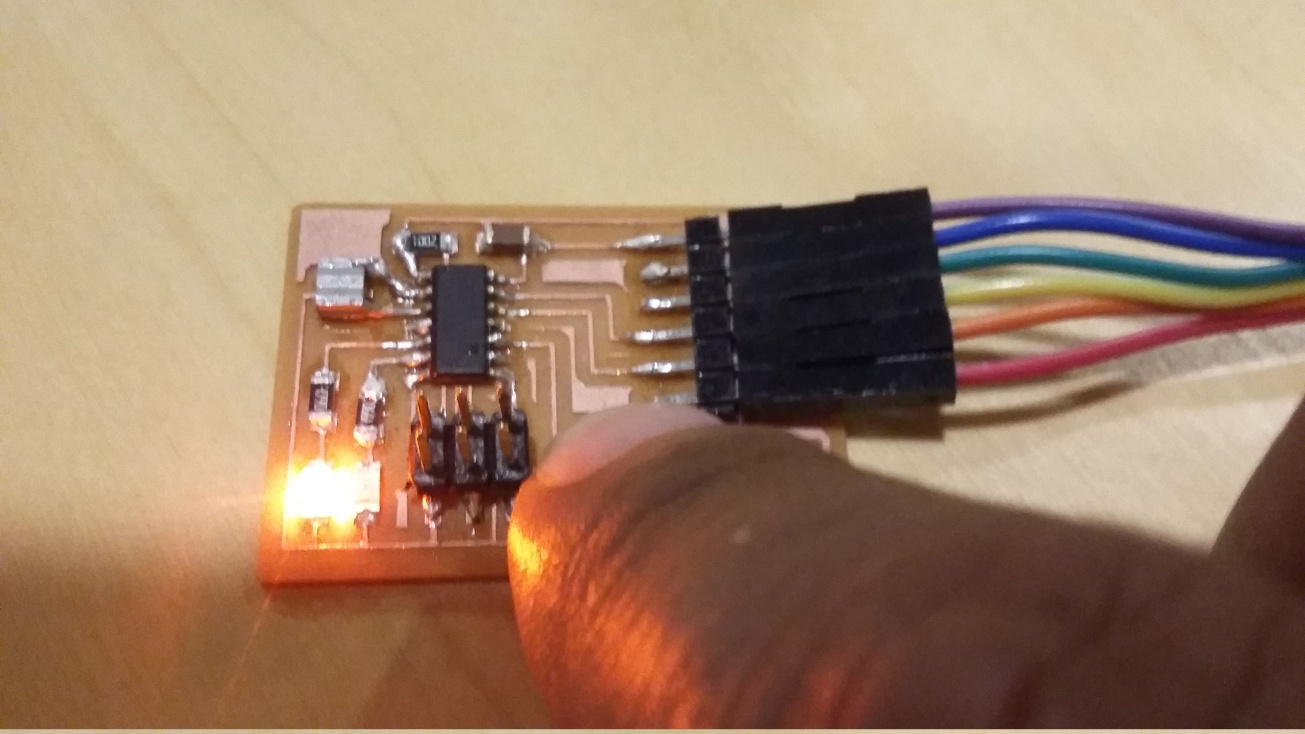
When I first started the programming, I tested to program Arduino with avrisp II because I had issues with my usbtiny programmer. I was able to debug those later, or actually it turned out that it was not the programmer but rather the circuit I was testing at that time which had an un-stable connection at one of ISP pins. I had to resolder and the circuit and usbtiny were good to go. So initially by simply running
avrdude -c usbtiny -p t44 -P usb -v
to test if both the programmer and the board are fine
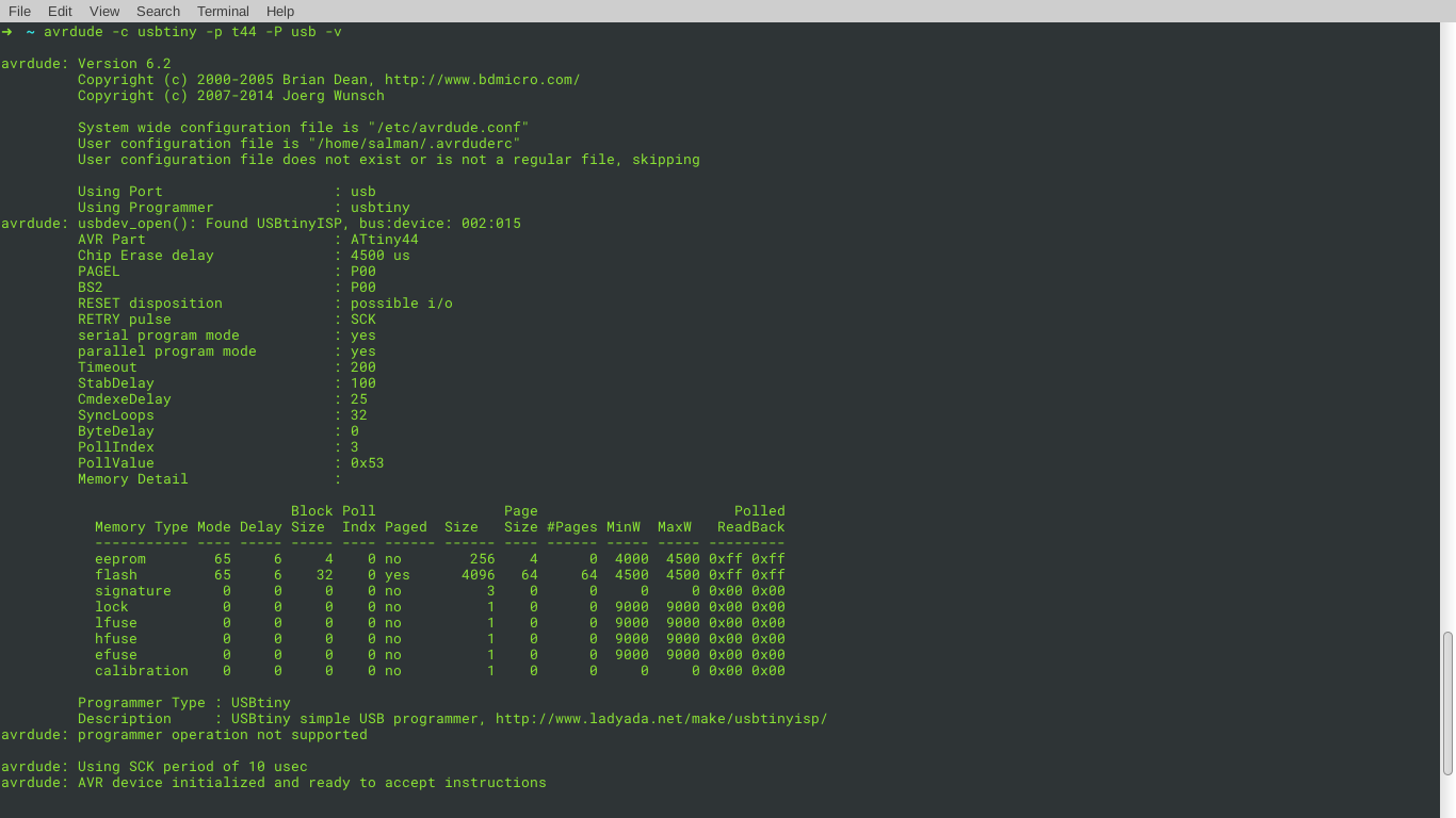
Right Click and Select View Image to see the details in the image
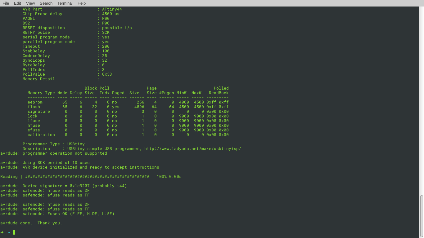
Right Click and Select View Image to see the details in the image
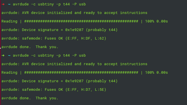
Which as seen was once not working and a bit later fine.
Following all the instructions at the example set by Neil, I thought I did all correct and even programming my fuses. Later I realized not, in between all this step and what happened later there was a detour to figuer out if any of my components(USBtiny programmer, FTDI cable, hello.echo board) had issues. I followed every single connection from the usbtiny and ftdi cable and the circuit, pin to pin trace by trace using a multimeter back and fourth.
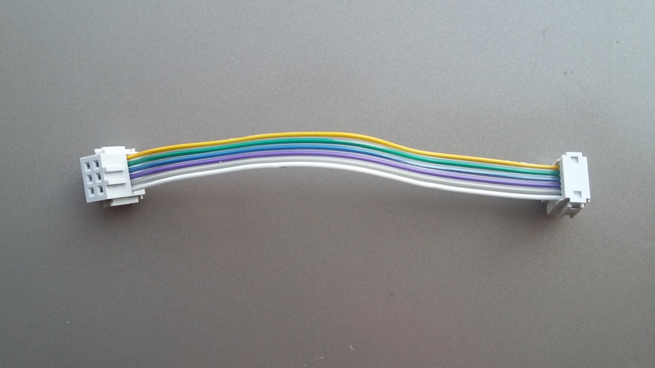
So to break out my debugging before proceeding i did the following: ( Franciscos recommendation) 1- Board :Testing with Multimeter the Hello world circuit, all traces and all pins. 2- Cable: Checking the connectors in the ISP connector pin to pin ( the first cable I did had an issue, I tried to find photos of that but I couldn't ) I simply did placed the connectors on opposite ends and both facing down, while the cable was straight as in the following image. The correct and easy way to avoid alot of twistig while connecing them to the isp pinouts is to have one connector facing up and another facing down.
3- FabISP(USBtiny programmer) : Checked that the board is recocnized when connected to a usb port, and followed traces and made sure I desoldered the jumpers correctly. 4- Checked that I am not using USB 3 port
later I came accross this link which also details the debugging process https://learn.adafruit.com/usbtinyisp/help
something also I learned was to use the simple command line
avrdude -c usbtiny -p t44 -P usb
to check if the avr device is initialized, it also gives an idea about fuse setup.
Programming with USPtiny
I started with the hello.echo circuit and program, which was programmed initially with no errors but when running the python serial script I got just uncomprehensable text.
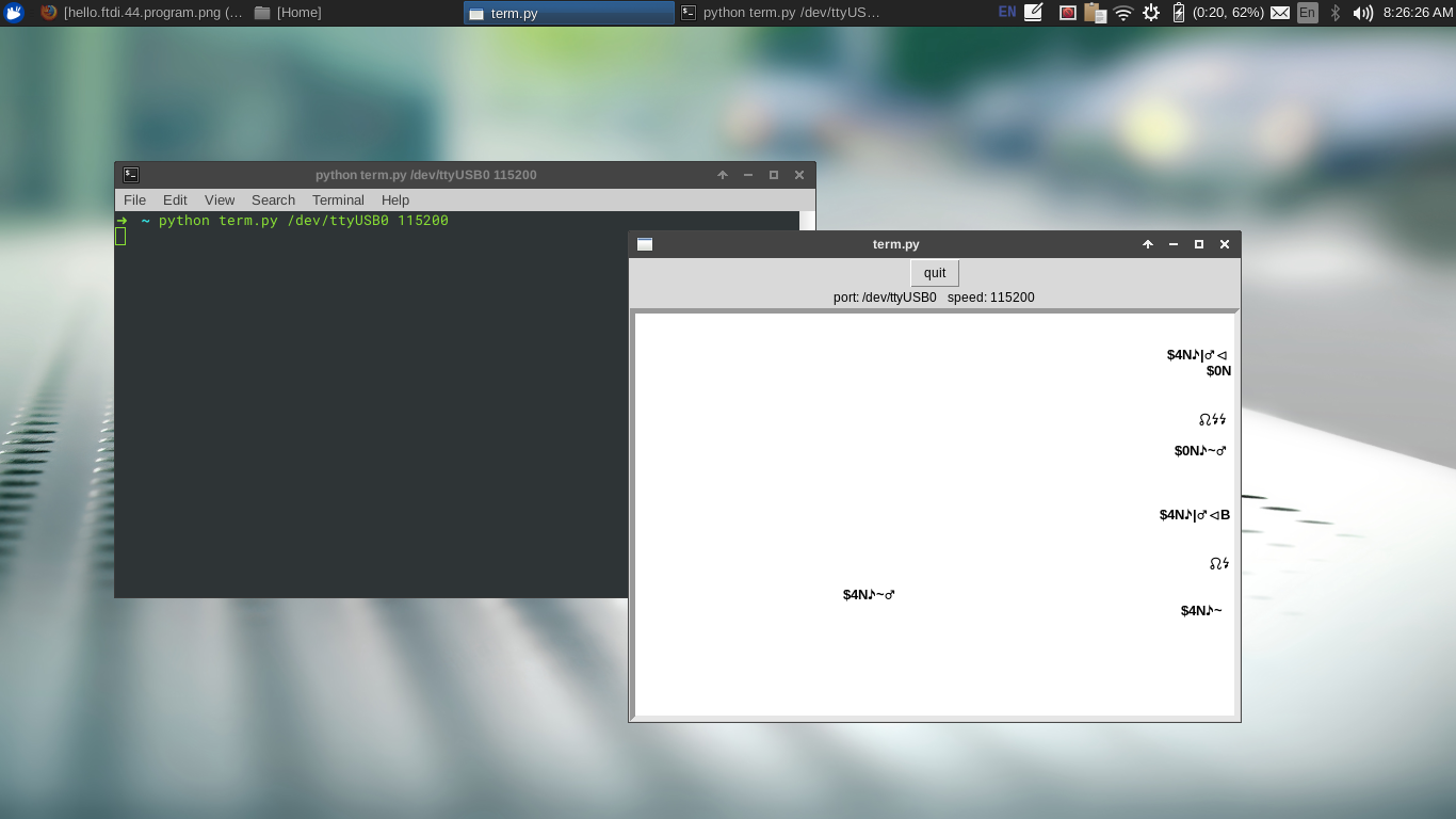
I thought initially that it's an issue again with my circuit. I decided to test with a simple blink code I used previously.
I realized that the circuit is fine. I noticed something not normal though, my dealy, the led took way longer time than the assigned. So I went on to test with Arduino IDE and program the same Attiny44A with a similar blink code.
void setup() {
pinMode(8,OUTPUT);
}

void loop() {
  digitalWrite(8,HIGH);
  delay(500);
  digitalWrite(8,LOW);
  delay(500);
}
Setting Arduino IDE for Attiny programming
Setting up Before uploading the Code
Select Tools–>Board–>"ATtiny24/44/48"(For Attiny45 select relevent group)
Select Tools–>Processor–>"ATtiny44" (The AVR used)
Select Tools–>Clock–>"External 20 MHz" ( This in Boards with 20Mhz Resonator")
Select Tools–>Port ( to select Serial Port)
Select Tools–>Programmer–>("USBtiny")
And again the time was not as assigned dealy. I even used a stop watch to figure out how much is this delay and if it's constant. I went on testing another board now, one that I had already done in week6. Then the program had no issue of timing because it was a button switching between two lights. So I checked it again using a simple blink script on Arduino IDE also. To my surprise I had the same issue of delay mismatch.
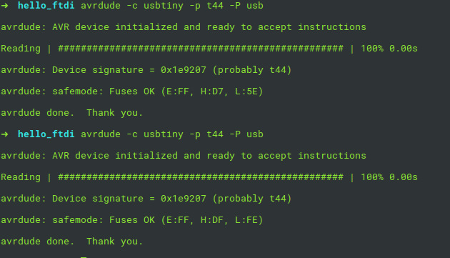
So as per the suggestions by my instructor Francisco, I had to check the fuses. Which as shown in the following images have been set differently for two Attiny44A circuits. The first is one from Week6 is and the second was the Hello.Echo circuit.
Though the two had the same external oscilator and chip, the fuses were not set the same. Then using the Arduino IDE i burned a bootloader on both circuits.
And the fuses looked different now. The before and after bootloader fuses setup is shown in the following image.
And once I had the blink program uploaded on both I was able to notice the difference.
by taking time of blinking with a delay set on 1000ms i got
I then tried a simple blink program in c using avrdude. But despite of having this run succussfully I still got the Hello.Echo program giving similar uncom
Programming an Attiny44 board with a Button and 2 LEDs
After setting the IDE to program an attiny board as mentioned previously. The next step is to check the data sheet. And specifically the pinout of an Attiny, to get the difference between all the available pins.
And when using Arduino IDE the mapping of the Attiny pins to those of an Arduino is essential to get the pin assignment correct.
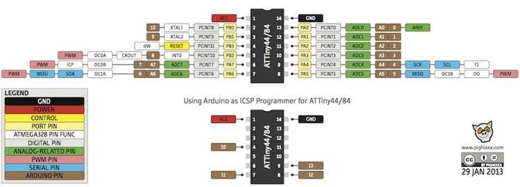
I wrote a simple code to switch between two LEDs after pushing the button. In the first state of the button ( LOW ) the led connected to pin 7 is on. And once the button is pushed ( State = HIGH ) the second led at pin 8 is on.

/*
 *           VCC--|--|--GND
 *           PB0--|  |--PA0
 *           PB1--|  |--PA1
 *           PB3--|  |--PA2
 *   Ard 8 = PB2--|  |--PA3 = Ard 3
 *   Ard 7 = PA7--|  |--PA4
 *           PA6--|--|--PA5
 *
 *  Ard = Arduino Pin
 *
 */

// set pin numbers:
const int button_pin = 3;     // the number of the pushbutton pin
const int led1 =  7;      // the number of the LED pin
const int led2 = 8;
// variables will change:
int buttonState = 0;         // variable for reading the pushbutton status

void setup() {
  // set the 2 LEDs pins as an output:
  pinMode(led1, OUTPUT);
  pinMode(led2, OUTPUT);
  // set the pushbutton pin as an input:
  pinMode(button_pin, INPUT);
}

void loop() {
  // if the buttonState is pressed switch the LEDs state
  if (digitalRead(button_pin) == HIGH) {
    // turn LED1 on & LED2 off:
    digitalWrite(led1, HIGH);
    digitalWrite(led2, LOW);
  } else {
    // turn LED1 off & LED2 on:
    digitalWrite(led1, LOW);
    digitalWrite(led2, HIGH);
  }
}