Week 9
Mechanical Design.
ASSIGNMENT:
1.) Make a machine, including the end effector.
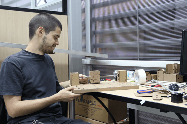
2.) Build the passive parts and operate it manually.
3.) Document the group project and your individual contribution.
ASSIGNMENT:
1.) Make a machine, including the end effector.
2.) Build the passive parts and operate it manually.
3.) Document the group project and your individual contribution.
Unlike previous weeks, in this assignment we had the task of a group project.
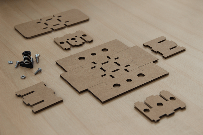
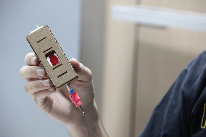
In this assignment my main contribution was the structural and mechanical design of the CNC milling machine pipe, using corrugated carboard of 1.5 millimeters thicknes.
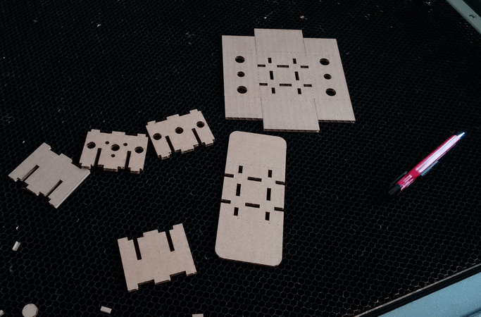
To start, with my classmate we downloaded the modules of the cardboard stages from "Machines that make machines" webpage.
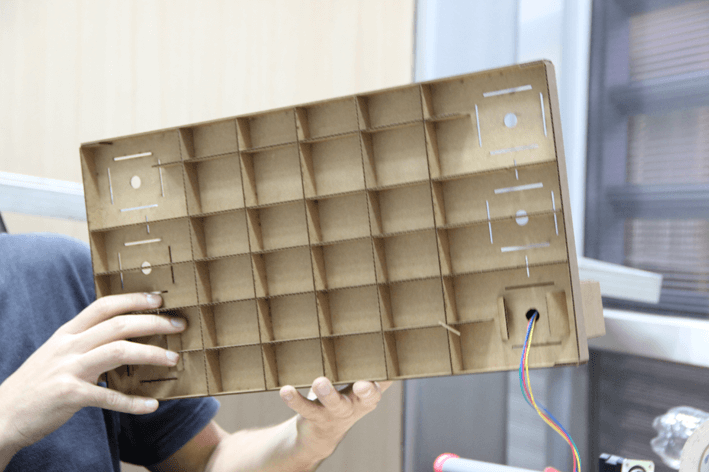
I can see that the cardboard modules use a considerable quantity of cardboard, and I redesign the modules with less material and I simplify more possible.
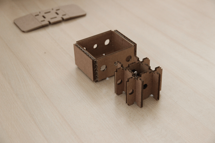
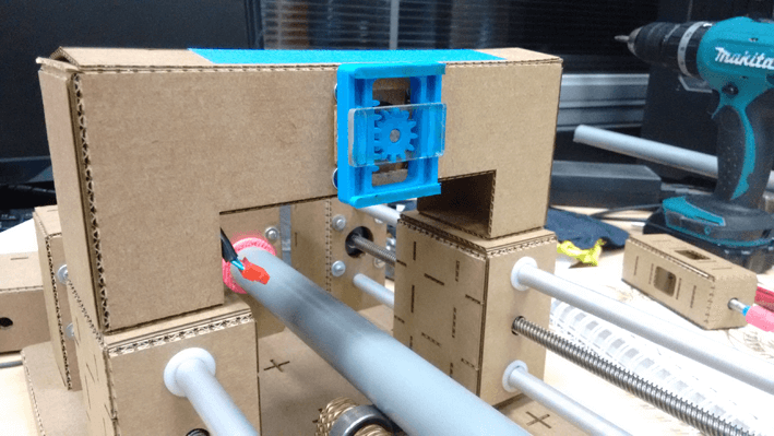
Another thing that can be detected in the above structure was the position of the anti backlash, which was located only on one of the outer surfaces of the carton and noticed a problem when moving. For this reason I have decided to put the anti backlash inside the box and modify it for more resistance at the time that this move.
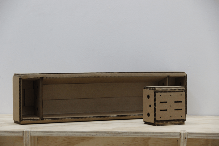
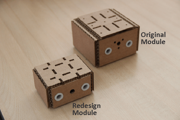
Here you can see the comparison in size of the original module and redesign, saving and simplifying material without losing the necessary strength in the structure.
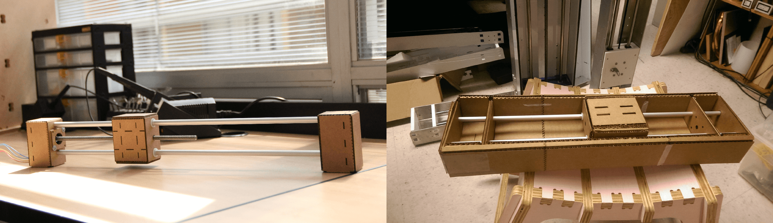
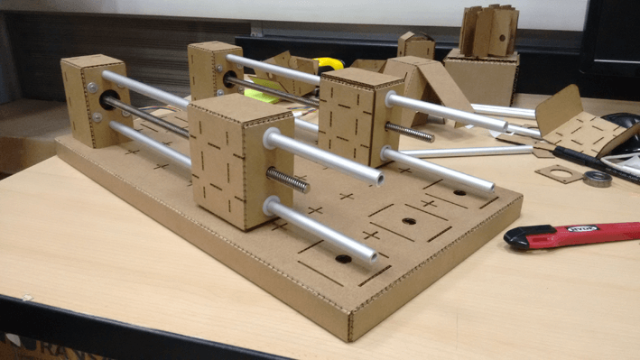
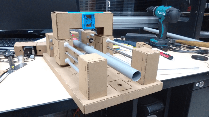
Trying to keep the idea of using only cardboard for design of the machine, I have designed a base where the entire structure is supported. This proved quite efficient but still needs some modifications to make efforts to be submitted to the machine during operation and support work properly.
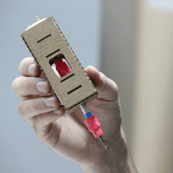
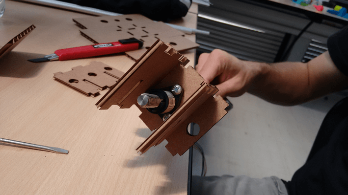
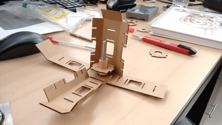
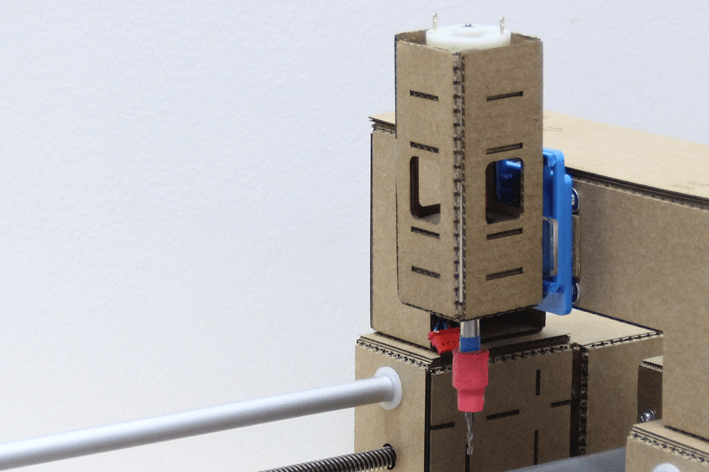
To assemble the spindle used as a reference found in the following link, with the variation that all structure is made of cardboard. The inside part is made equal to the reference that I have observed.
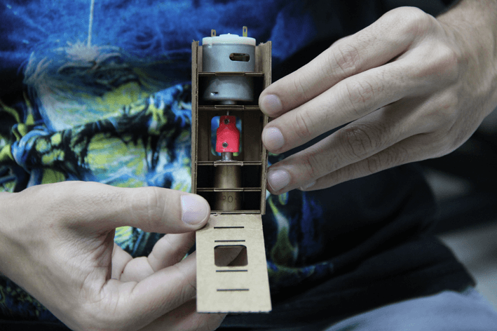
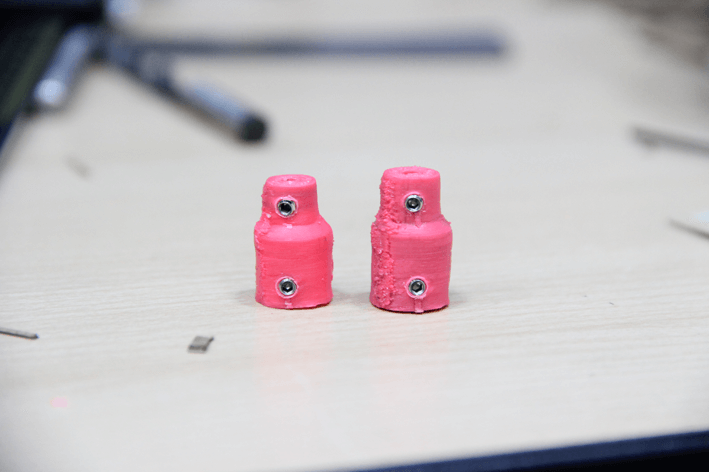
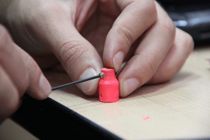
At one point I had the problem that we did not have couplings to the connections between the DC motor and aluminum shaft, therefore, had to design fittings in 3D and then print them on ABS.
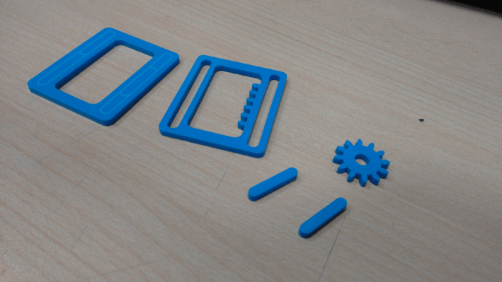
In the Z axis use a stepper motor for horizontal movement of the head holding the mill tool. In order to move the head I designed a mechanism consisting of a rack and pinion on acrylic of 3mm thickness.
Here ends my contribution to the project! So far, I think it's the most challenging assignment. We now need to review the programming part of the gestalt.
All photos were taken by my classmate Gabriela Mojoli, you can see her work here.
- The carboard structure works very well.
- I need to remake some pieces of the machine.
- Better distribute of the work.
I'm currently taking this course in FAB LAB TECSUP, in Lima-Perú, through CIDI FADA UNA with the support of CONACYT and PARQUE TECNOLOGICO ITAIPU FOUNDATION


©DESIGNED AND BUILD BY FABIO IBARRA - FAB ACADEMY 2016
EMAIL: fabioibarrab@gmail.com