Week 6
Electronic Design.
ASSIGNMENT:
1.) Redraw the echo hello-world board.
2.) Add (at least) a button and LED (with current-limiting resistor).
3.) Check the design rules, and make it.
3.1 ) Extra credit: simulate its operation.
ASSIGNMENT:
1.) Redraw the echo hello-world board.
2.) Add (at least) a button and LED (with current-limiting resistor).
3.) Check the design rules, and make it.
3.1 ) Extra credit: simulate its operation.
This week the assignment is to redesign the "Hello World Board" where Minimally had to add an LED and a switch button to the card. Its was my first experience making electronic design and has been a little hard for me but I managed to finish the job.
To draw the board I downloaded and install Eagle. To start I had to download the library of component from Fab.lb and install the library to have all the necessary components in EAGLE at the time of drawing the board.
To start with the basic on Eagle, I saw this Tutorial on youtube with the basics of schematic and board design.
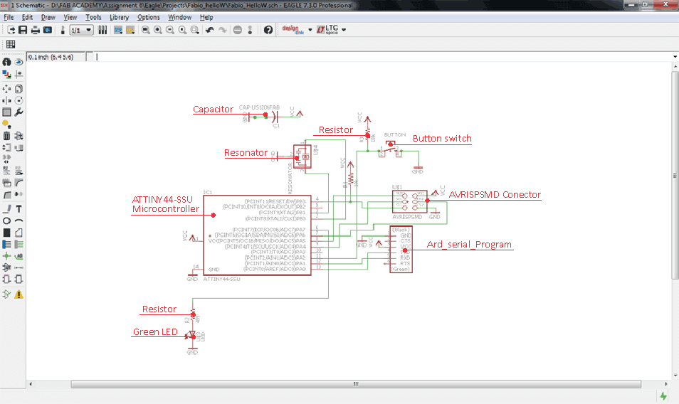
This is how my schematic draw looks like:
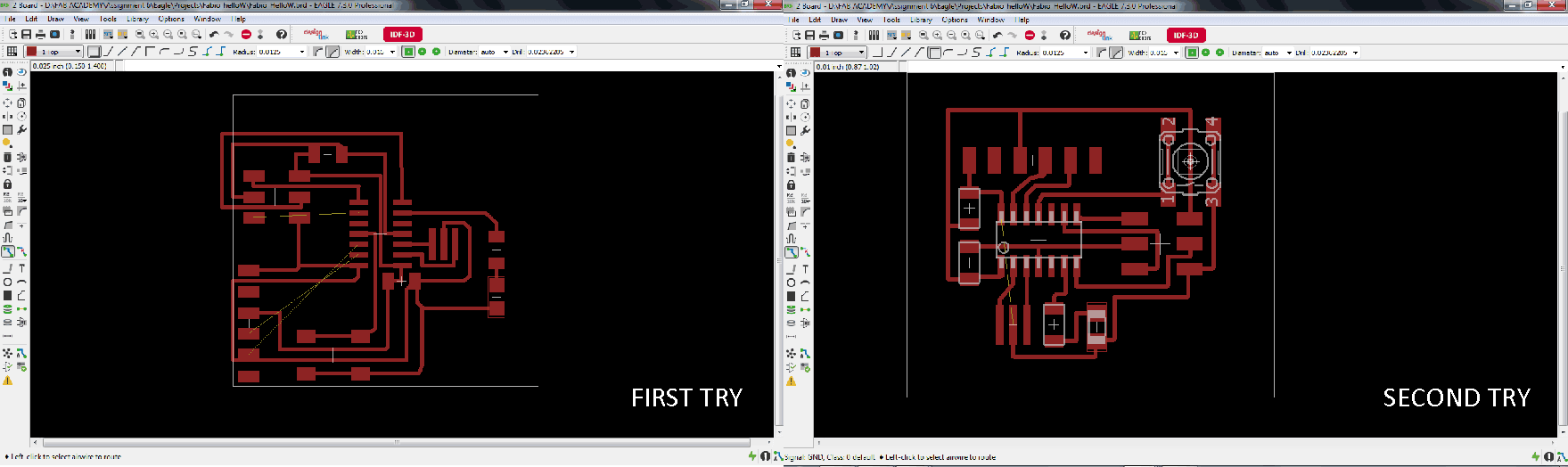
Once finished my schematic I tried to generate the board with the button "autoroute" but reading some tutorials I see that it is not appropriate because the program locates the routes in different layers, that was not what I needed for my board.
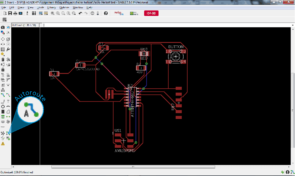
Leaving aside the "autoroute" tool, I had to design the routes manually to distribute in the most appropriate manner and avoiding errors generated previously by the "autoroute". The manual design of the routes took me a long time because the routes intersected between them and that made it difficult to have them all on the same layer.
I made several failed attempts in the process of drawing the routes, I always stayed some can not connect and the worst is that I could not understand why !!!
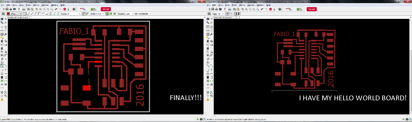
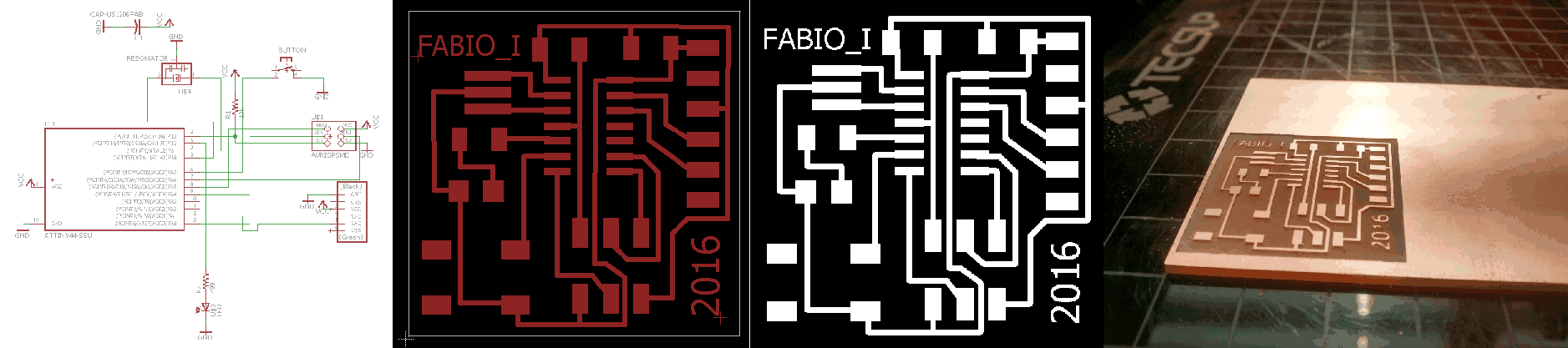
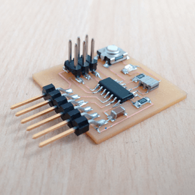
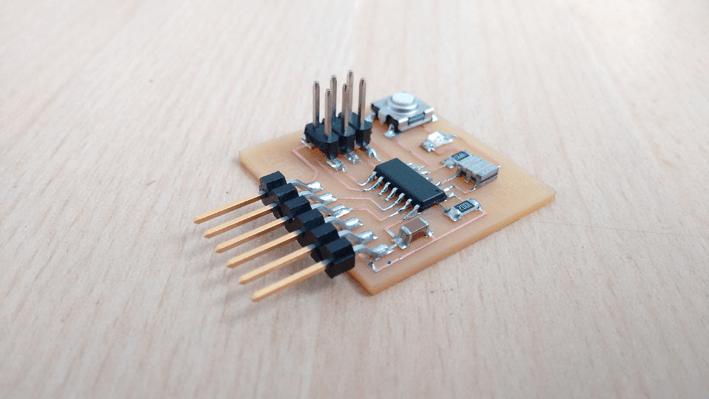
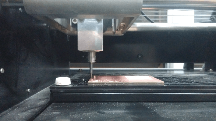
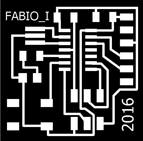
So, finally I could have my board: firstly had to prepare the circuit schematic, then had to draw the routes with Eagle and then used the MODELA MDX-20 to milling the circuit on a copper board.
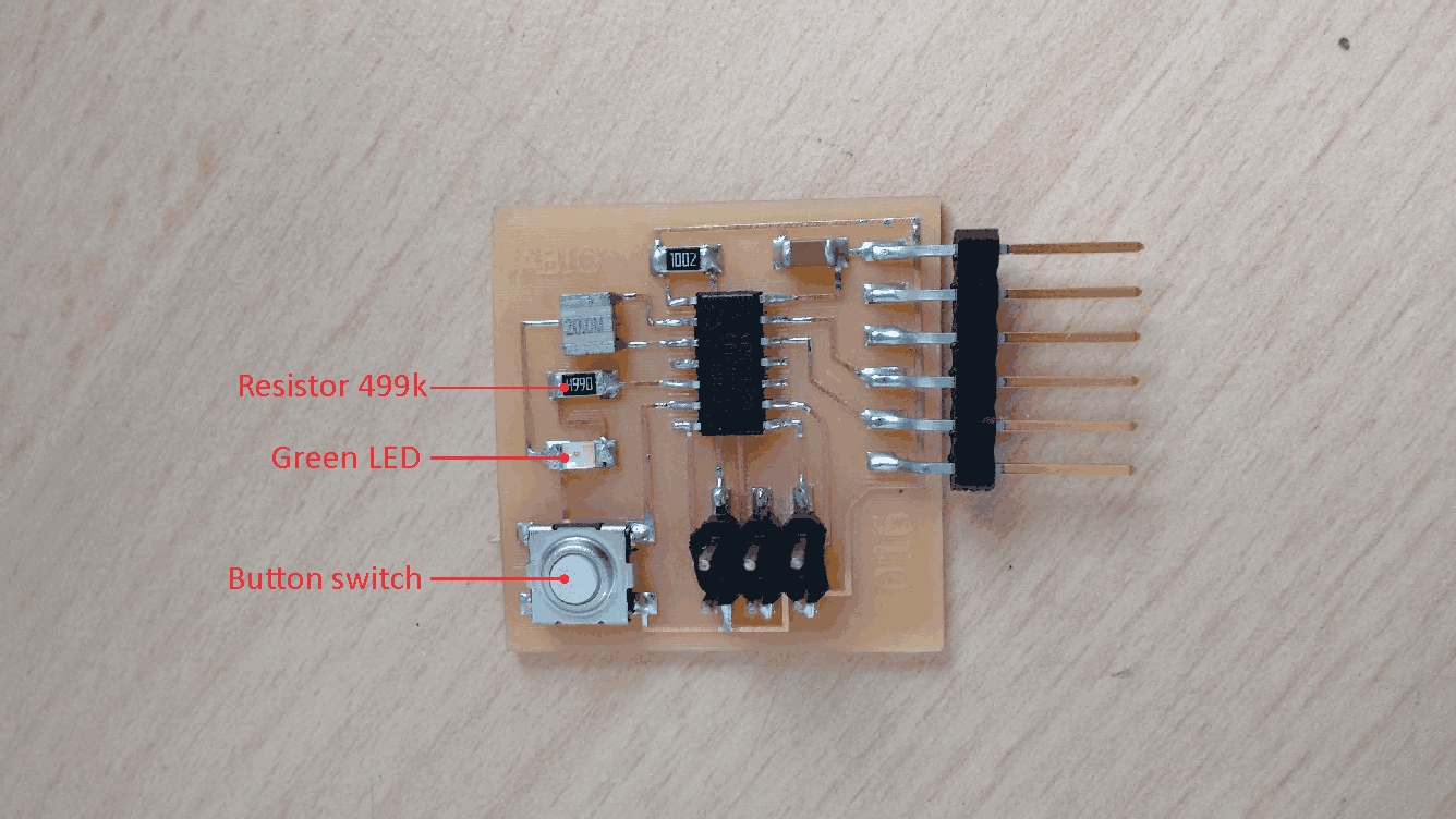
On the board photo you can see the button switch, the LED and its respective resistance, including in the circuit HELLO WORLD.
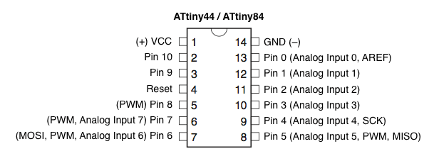
Before burning the firmware, I looked for a scheme of ATTINY 44 microcontroller to view the equivalencies with arduino pins.
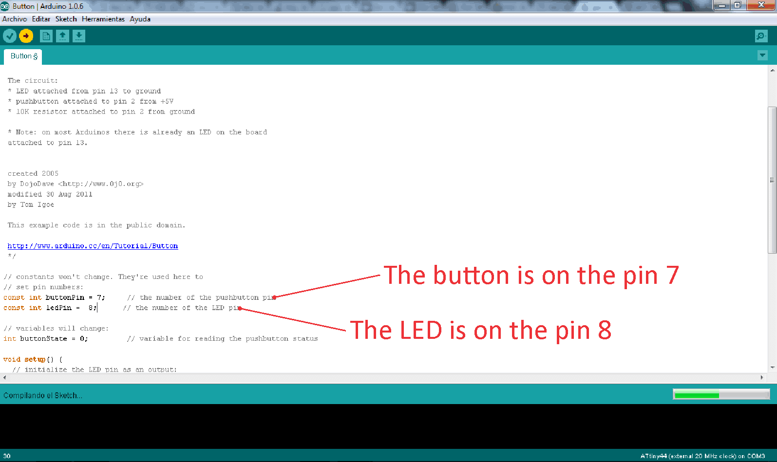
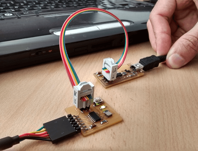
After loading the firmware, I checked the operation of my HelloWorld Board and worked perfectly!
 \
\
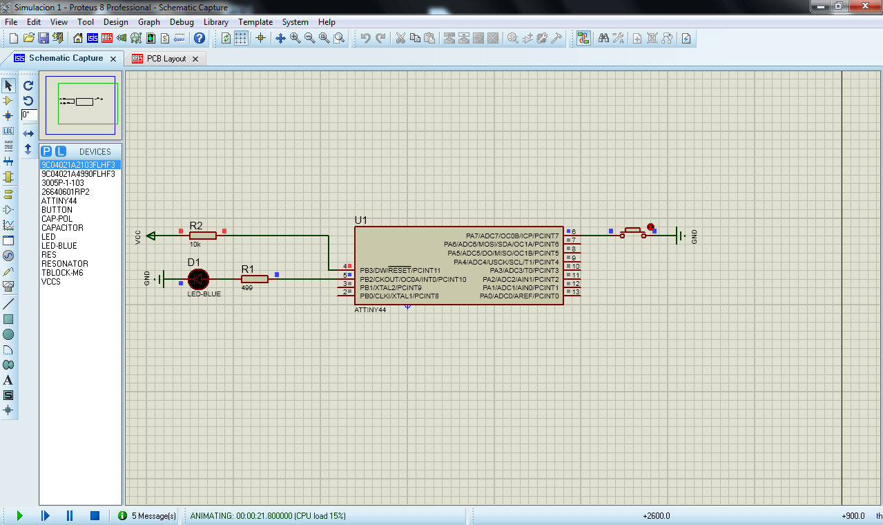
After fixing the errors on the microcontroller, the simulation did not generate errors but the LED does not light. It's a mistake I have not yet been solved.
Eagle file: Fabio_HelloW2.brd
Eagle file: Fabio_HelloW2.sch
Circuit PNG: Fabio_hellow2.png
Circuit Cut Out PNG: Fabio_hellow_cut2.png
- My Hello World Board works very well.
- My FabISP board still works great.
- The simulation of the circuit failed.
- The simulation on Proteus need to be fixed..
- Practice with Eagle to draw circuits.
I'm currently taking this course in FAB LAB TECSUP, in Lima-Perú, through CIDI FADA UNA with the support of CONACYT and PARQUE TECNOLOGICO ITAIPU FOUNDATION


©DESIGNED AND BUILD BY FABIO IBARRA - FAB ACADEMY 2016
EMAIL: fabioibarrab@gmail.com