Week 4
Electronics Production.
ASSIGNMENT: make an in-circuit programmer.
ASSIGNMENT: make an in-circuit programmer.
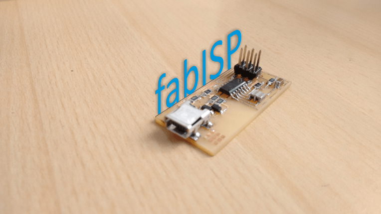
In this fourth week, the assignment was to build our own "hello" electronic board, an card that will allow me to program other microprocessors trough a USB cable and 6-pin IDC, to 6-pin IDC cable.
Here in the Fab Lab TECSUP there is a good teaching staff in electronics, who gave us a talk on the principles, definitions and tools for electronic production; This was very useful to understand how the elements that I used in my electronic board work.
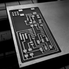
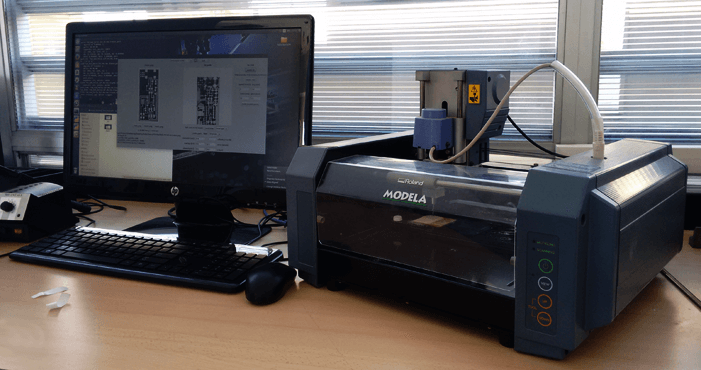
In order to mill the board I used the ROLAND MODELA MDX-20 and the Fab Modules Software.
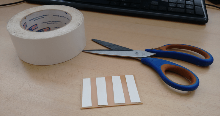
I secured the board in the milling machine with double sided tape to keep the model from moving in the milling machine and loosing the 0,0 point.
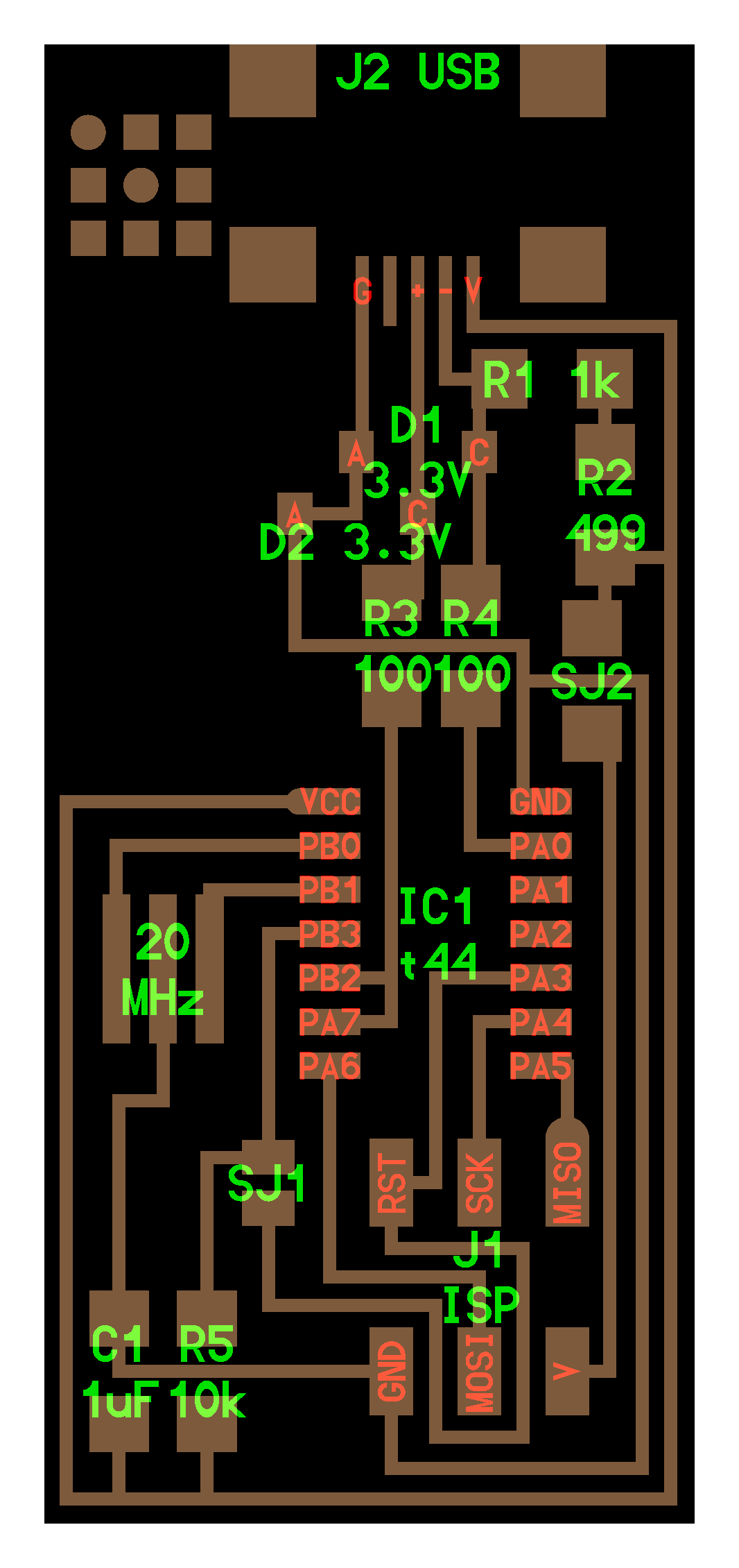
I open Fab Modules and make Click on the “load" button and selected the file "hello.ISP.44.res.traces.png". Press make path to see a preview of the milling.
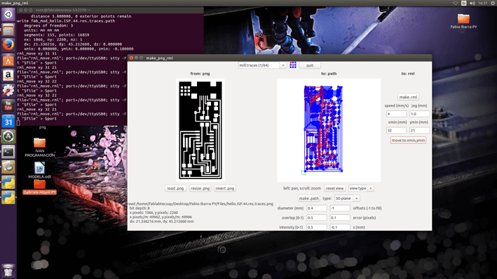
- Diameter: 0.4 mm
- Overlap: 0.5 mm
- Intensity: 0.5
- offsets: - 1 mm
- error (pixels): 0.1
- z: - 0.1 mm
After the setting in Fab Modules, I defined the point "0,0" in the copper plate and press the button "send it" for machining.
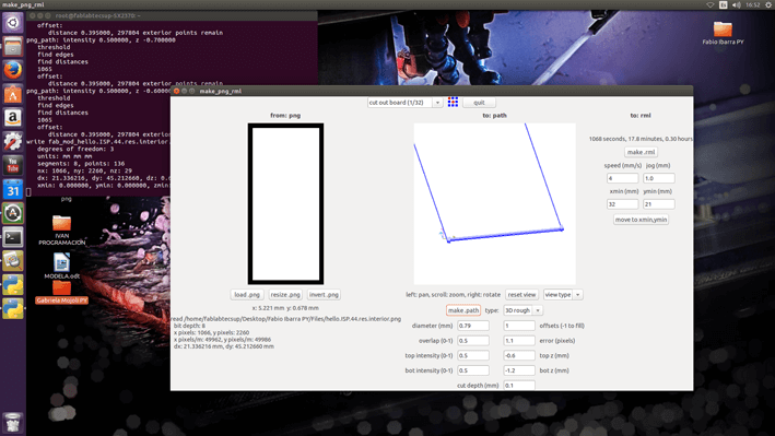
Once finished the milling process, I repeated the same steps but this time I select the file "hello.ISP.44.interior.png" to cut out the electronic board of copper board.
- Diameter: 0.79 mm
- Overlap: 0.5 mm
- Intensity: 0.5
- offsets: 1 mm
- Top Z: - 0.6 mm
- Bot z: - 1.2 mm
- Cut depth: 0.1 mm
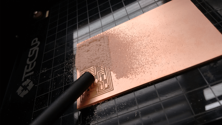
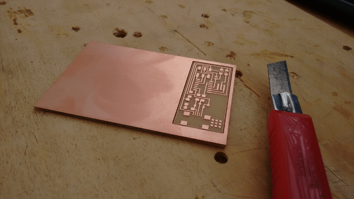
At finished the milling and cut out process, I cleaned the dust with a bacuum and take out my electronic board to cleaned with a metal brush.
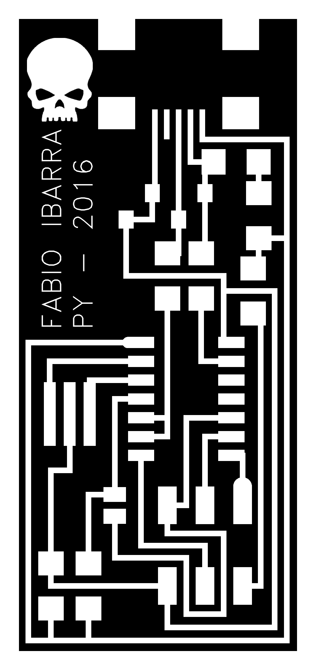
Taking advantage of the customization that gives us a Fab Lab, I use Photoshop to customize my electronic board adding a picture and my name.
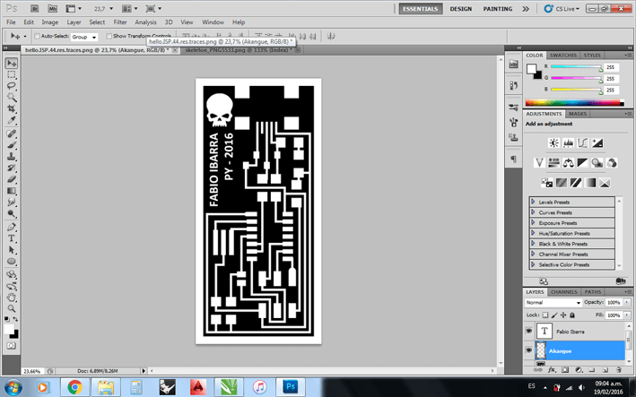
When editing the original file of the plate, it is important to consider the size of the file, to avoid problems of size at milling.
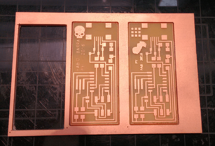
I machining more than one plate to have reserves, in case the welding process goes wrong.
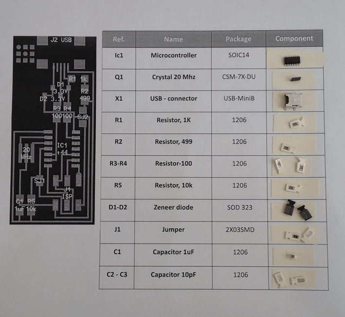
To start I made a list of the necessary components to assemble my electronic circuit, because they are very small and I stick them on a piece of paper to organize and identify the components quickly.
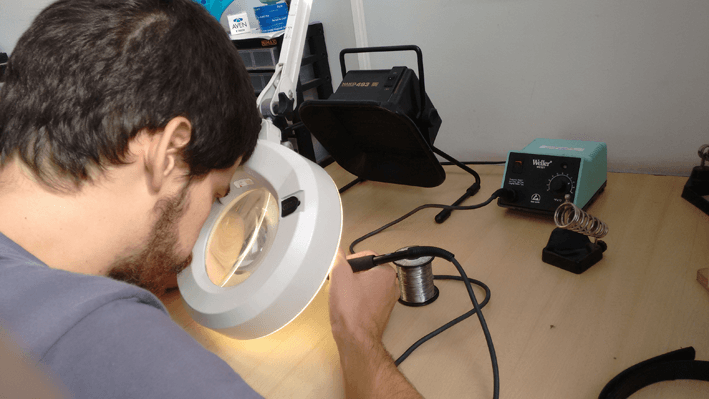
Welding zone and tools used to build my electronic card.
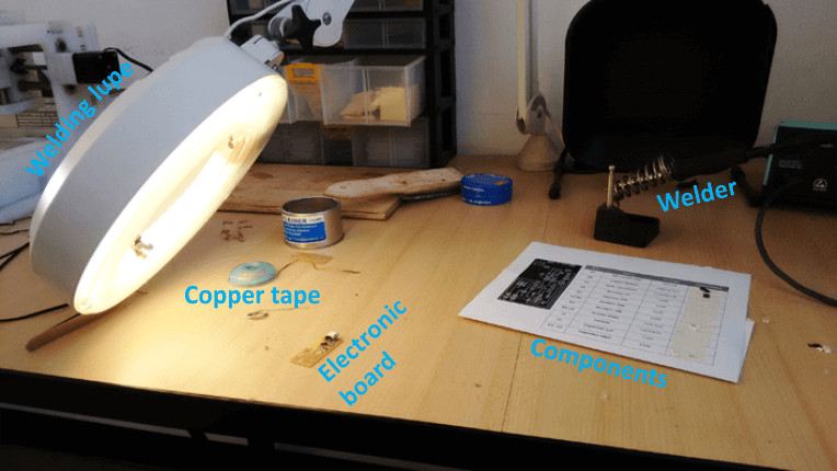
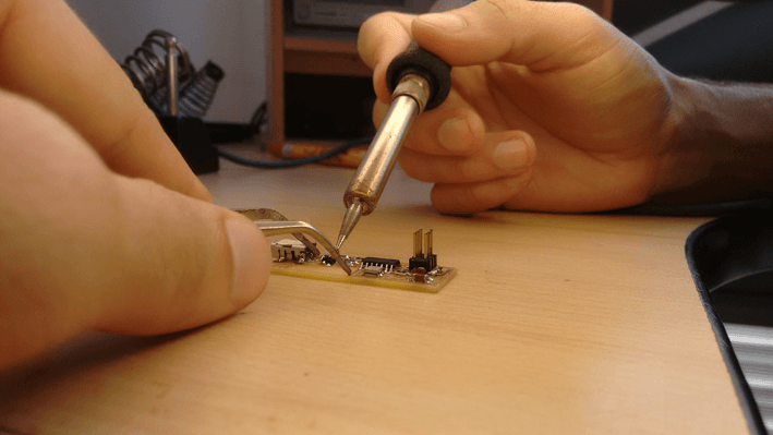
I found the soldering it's too difficult because it's the first experience i have with electronic components, but with patience and steady hands I can build my electronic card.
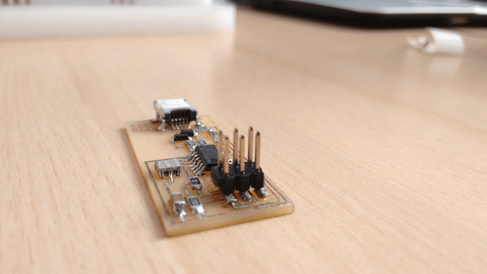
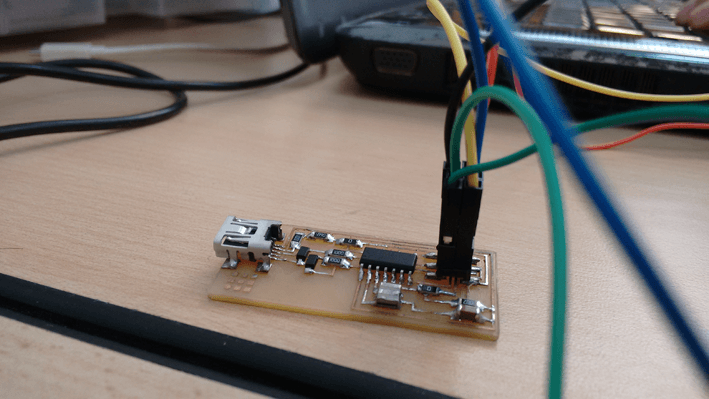
Before connecting the plate to the programmer, I have made a testing the circuit to check that no short circuits or shoddy welding in the components.
I made the testing with help of a tester and I revise one by one all the welds in my electronic board.
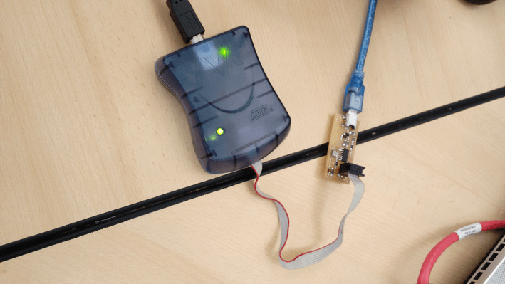
To ensure that my electronic board don't have errors, I connected to AVRIPS MKII waiting for the green LED turn on; but it was not that way. I had to check the welds and the circuit repeatedly and until after several attempts, finally the green LED turn on!!!
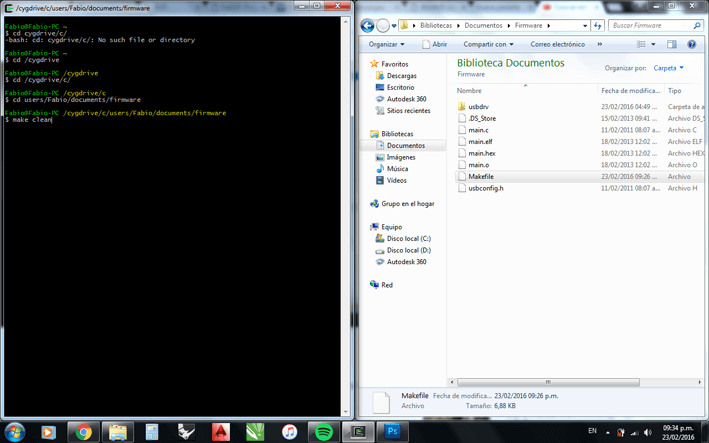
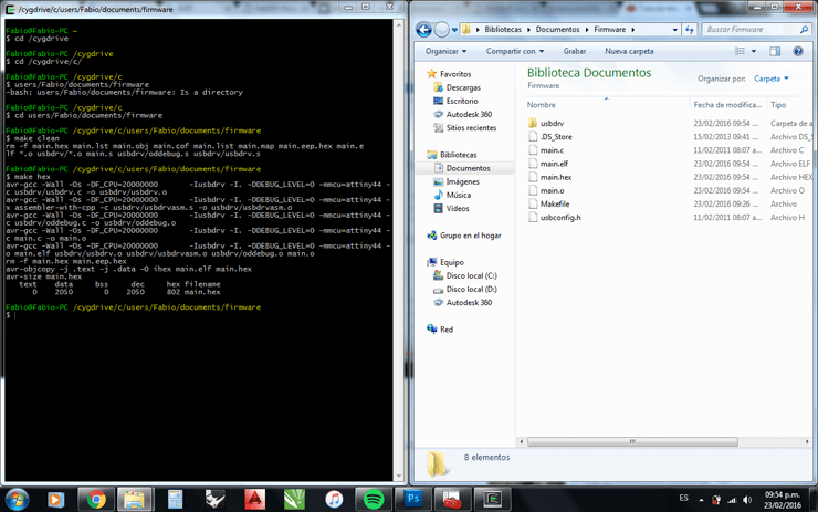
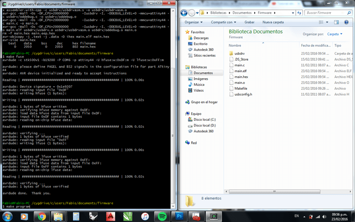
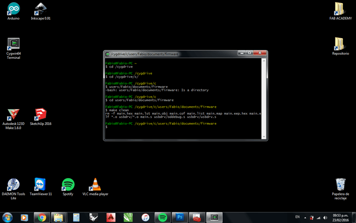
Later, I downloaded the firmware for my board and run the TERMINAL in Ubuntu to follow the instructions of the Fab Academy tutorials.
I invested a lot of time trie to programm my card bud did not work, with ubuntu when I running the "MAKE FUSE" command, always generate an error that could not solve it. I was almost a whole day trying to solve the problem but finally decided to discard and try another method through ARDUINO.
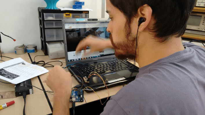
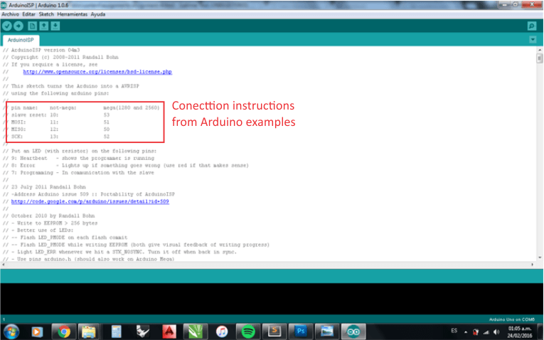
To make Arduino UNO function as an ISP, I had to load the firmware that the microcontroller itself has by default in the software. In the same firmware code also explains how to make connections between the pins Arduino UNO and FabISP.
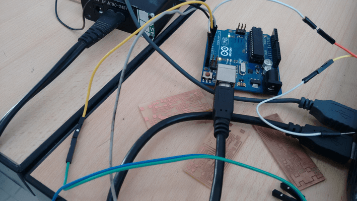
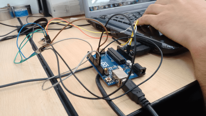
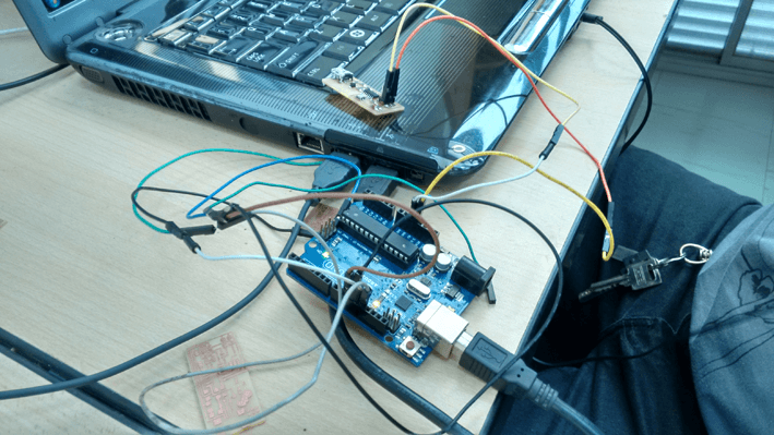
I used Arduino with windows, and follow this nice tutorial made by my friends of Fab Lab Zoi from Ecuador, they helped me to finish my programmation because i have problems in the process.
So this way I can program my electronic board, it was a pretty heavy assignment but so far, I think it is the assignment where I learned the most.
Circuit file: hello.ISP.44.res.png
Circuit file: hello.ISP.44.res.traces.akangue.png
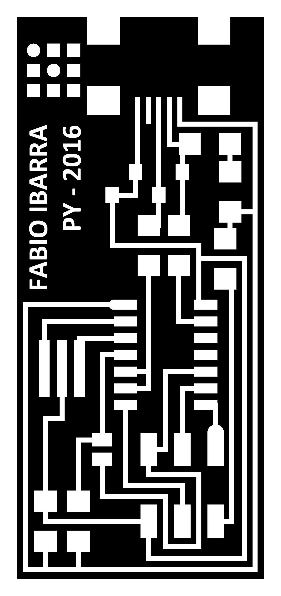
Circuit file: hello.ISP.44.res.traces.fabioibarra.png
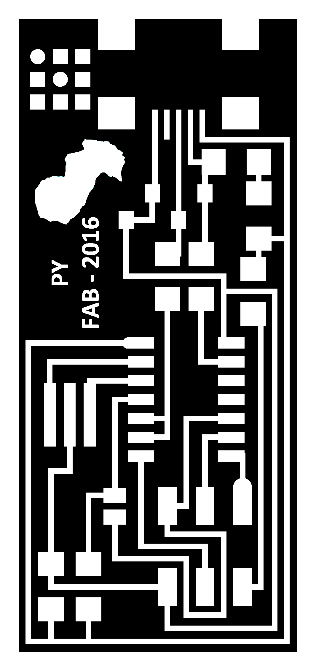
Circuit file: hello.ISP.44.res.traces.paraguay.png
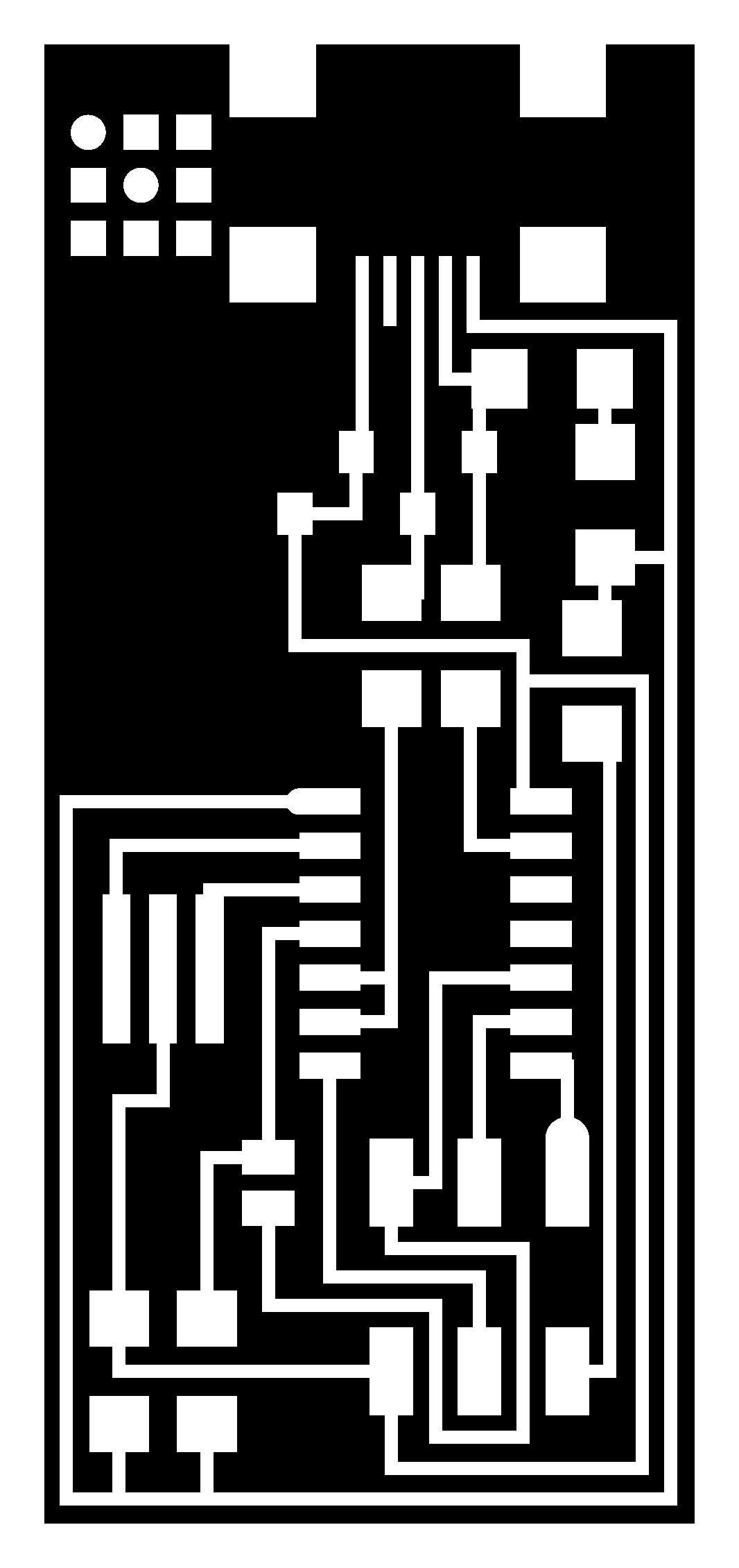
Circuit file: hello.ISP.44.res.traces.png
Circuit file: fabisp_drd.png
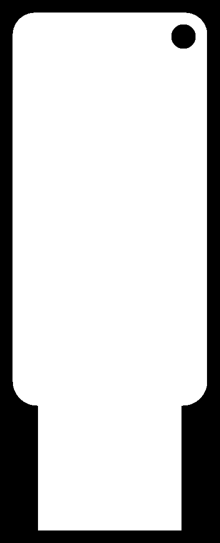
Circuit file: hello.ISP.44.res.interior.png
You can download the heavy files (more than 1MB) here from DROPBOX.
- Fab Modules proved a good software for driving the milling copper plates.
- I learn the basic about electronic.
- I used two types of programming tools (Fab Modules/Ubuntu and Arduino/Windows).
- The programation process with ubuntu because the AVRIPS MKII it does not work.
- Welding skills.
- Introduce me more in the Fab Tutorials.
I'm currently taking this course in FAB LAB TECSUP, in Lima-Perú, through CIDI FADA UNA with the support of CONACYT and PARQUE TECNOLOGICO ITAIPU FOUNDATION


©DESIGNED AND BUILD BY FABIO IBARRA - FAB ACADEMY 2016
EMAIL: fabioibarrab@gmail.com