WEEK 13 - Output devices
TASK:
Objectives:
- Design output for 2x servos
- Mill and stuff board
- Program and test board
Design output for 2x servos
Eagle files: Hello_Servo_KT.sch
Hello_Servo_KT.brd
The task for this week was to look at how to create a digital output.
This is an opportunity to explore ways to manifest idea for the final project and to find ways to impliment the outcome.
Since the final project explores the idea of movable building facade, operating servos (mechanical motors) would be an obvious choice.
Besides studying Fab Academy's servo board,
the assignment also looked at work by various others such as:
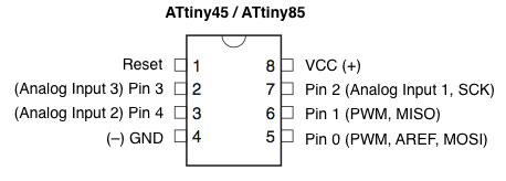
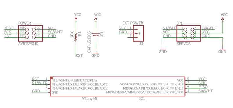
- ATtiny45 (see image of connections below)
- Capacitor 1uf
- Resistor 1K
- 2x1 header- For external power
- 2x (1x3) header- For Servos
- 2x3 header- For connections with programmer
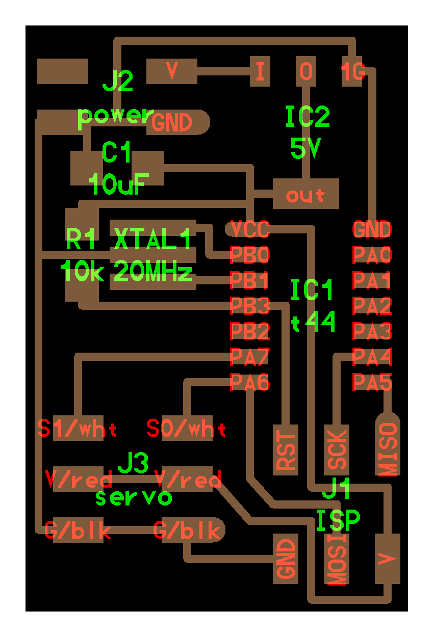
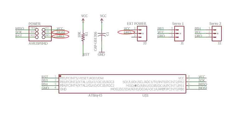
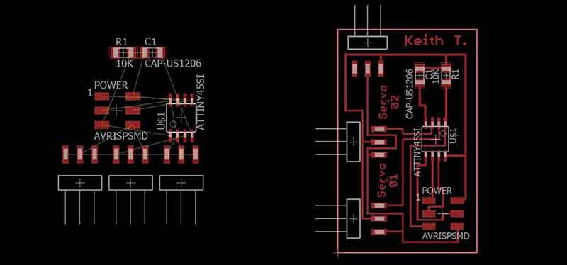
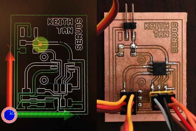
The following are images of first attempt of schematics and board laid out for this particular assignment. Due to limited space, servo headers were placed at the same side to allow easy connections. As part of the design, the servo headers were soldered as seperate connectors to allow flexibility. During placements of the connections, errors were detected due to "...part has no value". This was resolved by inserting a value ( e.g. 10K) or name of component part. This design was however proven to be faulty and contains errors (as circled in red below) such as naming and routing errors. It took 2 more designs before realizing these errors.
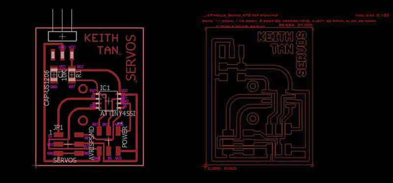
Final attempt on designing something that works with help from team mates. The servos connections were consolidated using a 3x2 pin header. By doing this, it created more opportunities for the traces to be routed outside components. Eagle files provided above consists of this workable design.
Mill and stuff board
CNC file: Hello_Servo_KT_top_etch.tap
Milling the PCB board was straight forward but there were some items that needed improvements.
Due to the size of ATtiny 45, traces that ran in-between the component were way too close to one another.
During the first (with the faulty design) milling, the parameters were also set a little too deep and it caused a few copper traces to be thinly milled .
However, upon checking connectivity, the board was found to be error free. Stuffing was followed right after.
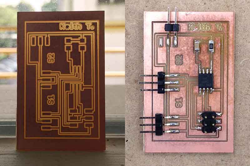
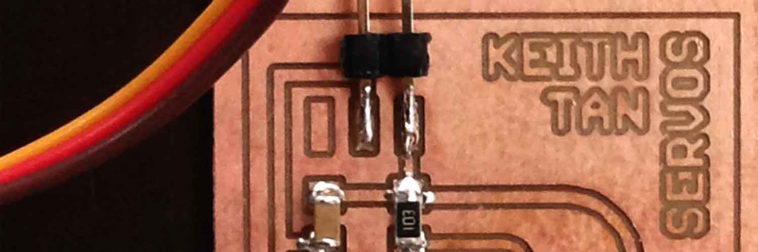
Here's the final attempt. Traces were less deep and hence the traces are thicker in width.
Program and test board
Arduino IDE: Sweep.ino C-code: hello.servo.44.2.c Hex-code: hello.servo.44.2.c.hex Make file: hello.servo.44.2.make Output file: hello.servo.44.2.out
Map of process:
Upload Arduino ISP to Arduino for programming Servo board (refer to Week 8) > open up Servo example from Arduino IDE> Burn bootloader to servo board> Upload example to board.
1) Programming the board happened to be the most tricky process. As Arduino IDE did not come with servo example for ATtiny 45, errors were detected during the compiling process. Below is an image of the error sketch.
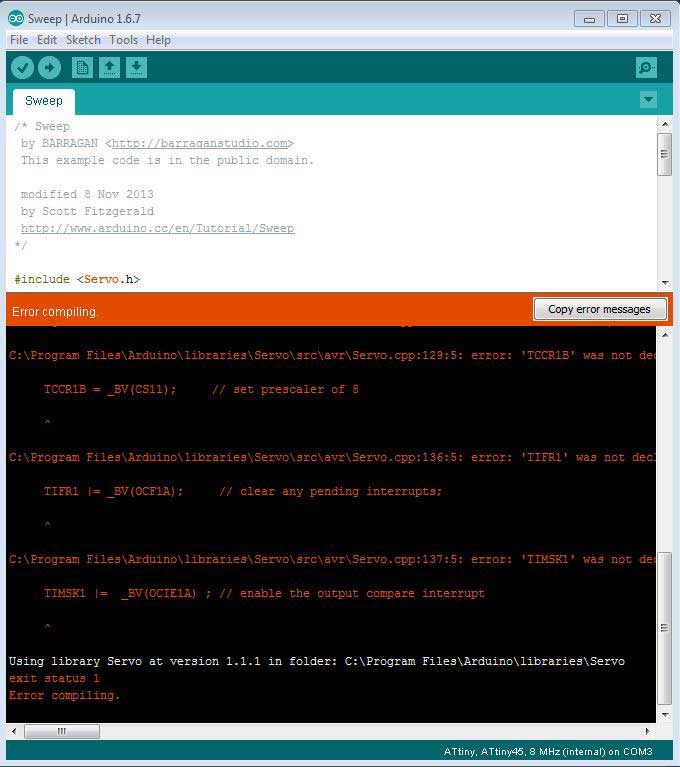
To resolve the incompatability of the IDE code, either of the following library can be downloaded and installed:
Softwareservo from Huang Yi pin
Servo8bit from Cunning Turtle
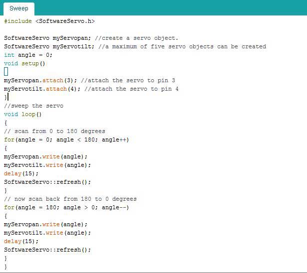
Here's what a typical servo IDE code should look like:
2) Another method of using AVRdude was adopted. This process has been elaborated during Week 8 but here's a more detailed documentation. With the help of Siew Chin, this was done by re-adapting Fab Academy Servo files.
-
a) Download the following files and create a folder where you can find them easily:
- hello.servo.44.2.make file
- MMCU=attiny45
- F_CPU = 8000000
- Change all avrdude -p t44 to t45
- hello.servo.44.2.c file
- Change Port A to Port B @ line 29
- At the following line, change direction to DDRB
- Following lines, amend pin numbers
- Open up command prompt from windows (Run>cmd)
- Go to directory where files are saved. Simply type "cd" and drag a file from the folder into command prompt. Delete the file name and make sure the closed inverted commas are placed at the end of the code. This will open up the directory.
- Type: cp hello.servo.44.2.make makefile, press enter
- Type: avrdude -P com6 -c stk500v1 -b 19200 -p t45 -U flash:w:hello.servo.44.2.c.hex, press enter
C (hardware PWM), makefile, C (two-channel, software PWM), makefile
Since, the servo board created comes with 2 servos, only files with 2 channels are needed.
b) Amend the following files by opening them in text program like notepad or sublime:
c) Next, follow the steps to flash bootloader to the ATtiny 45 servo board:
Note: -P has a capital letter P, com6 is the port channel, stk500v1 is ID that can be found in Arduino C code window after compiling sketch, 19200 is the bud rate, t45 (you guessed it) is ATtiny 45.
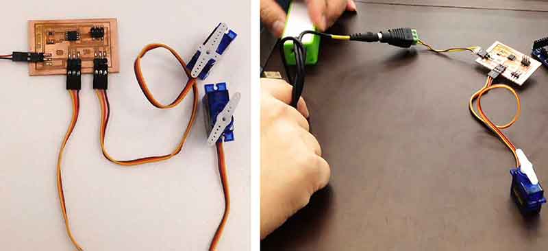
3) Finally, the servos are connected to the board with arduino as ISP. Data sheet for Micropik SG90 micro servo can be found here: http://www.micropik.com/PDF/SG90Servo.pdf
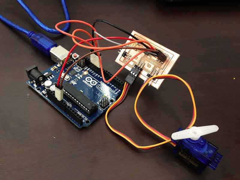
4) Once the burn bootloader is completed, arduino can be removed. External power source was then connected to the 2 pin (VCC and GRD) power header to turn on the servos.
Reflections
This week has been outrageously fun and the team has achieved a lot by working individually as well as helping one another with troubleshooting and leaning from one another. One of the biggest lesson learnt this week was to ensure that the schematic designs were checked before milling and PCB board to be milled carefully. Initially the first design was thought to be error free and the servos were reacting to the programin jittery manner. After 3 attempts to mill and stuff and program, it turns out to be due to design error. What a lesson learnt! All-in-all, it's been a great week!
Check out my video below!

Related Projects