2016
Output Devices Apr 27. 2016
This time it was time to experiment with output devices. Again, I thought of something that I could use as a part of my final project and made a decision of interfacing with stepper motors, I also wanted to experiment with more challenging PCB making. Therefore I picked Atmel ATMega16u4 that was stocked in our Fab Lab and also listed in Fab inventory. I found an example schematic on the internet that I used as a starting point for my design.
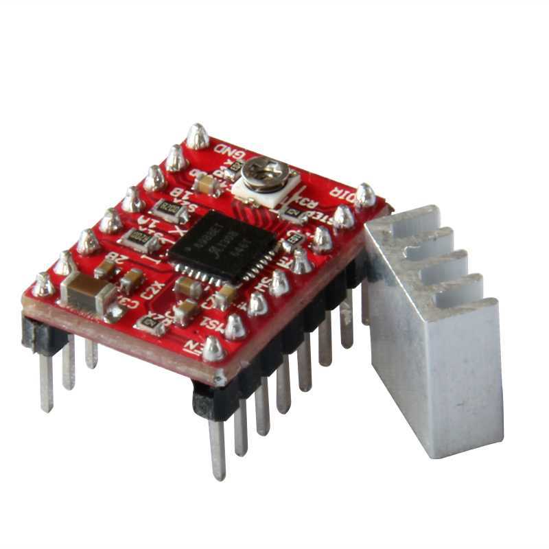
As a stepper motor controller I decided to use a copy of the Pololu A4988 driver carrier that I picked up from Ebay about a year ago. The price of these modules are around $2-$3 including shipping so there is no sense of doing the board from scratch.
I also found Eagle library component of the board so I can integrate the boards to my main design.
I started to edit the design and pretty soon it came obvious that I would need a double sided PCB to fit the controller and the stepper driver modules into one PCB.
I let Eagle do the autorouting and I had to allow 20 vias and clearance was dropped to 10mil in order to have no unrouted connections. I made minor changes to the outcome and added two alignment holes that were exactly in the middle horizontally upper and lower sides of the board, I used vias as these holes and I found couple of 1/32” pins that were tight fit to these holes.
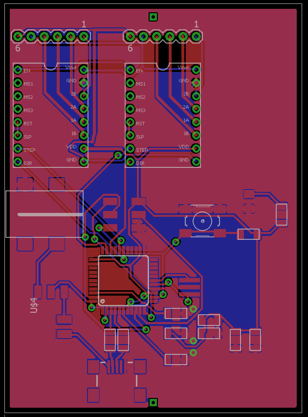
I produced five images from the Eagle board:
- Top layer with holes and vias I processed the png image as described in Assignment6
- Holes and vias. The monochrome image produces white circles in black canvas. I used Gimp Fuzzy select tool to select the black area that left the white circles and black inner area of the circles unselected. Then I poured white paint to the selection and was left with the correct position and size of each hole.
- Alignment holes only. Delete all but two dots from the above. I used 4mm depth for the stock thickness.
- Bottom layer mirrored. Using Tools-Transform tools-Flip command to make the flipped miiror image of the bottom layer
- Outline
The usage of Fabmodules is described in Assignment4. No special tricks there. Just to remember drill deep alignment pin holes that go deep enough into baseplate before moving the board. And do not touch XY zeroing during the process. Z axis needs to be zeroed every time the bit is changed.
The board came out OK. The flipping did not cause any issues and the alignment was very precise between top and bottom layers. I had very thin wires and through hole pads were a bit thin and therefore soldering the components was a challenge. I decided to give it a go. I soldered vias with a wire and by hand. This was nasty thing to do but since we did not have any rivets, this was the only option. Also the vias could be two small to use any rivets. The only other option would be making coper plating.
Some of the vias were underneath the microcontroller thus making the height of the via soldering thin.
Before I connected power, I tested the power against ground and found a short. After debugging, I could not find the cause for it and I made a decision to produce another board and make less vias and bigger clearance when possible. That is, however, not possible at this stage time wise.
I tested the stepper motor drivers with Arduino and using just wire connections according to this tutorial and Youtube video that verified that the modules work.
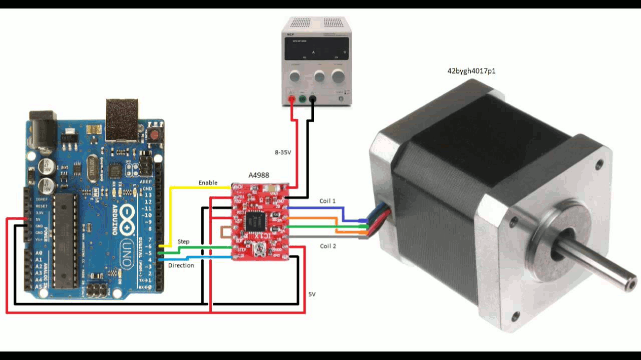
I used this code from the tutorial to test the stepper in action. It rotates the stepper half a turn in one direction and a whole turn in other direction if you have the connection as above that uses 1/2 micro stepping . If you have no micro stepping, it would be one and two rotations.
const int EnablePin = 6;
const int stepPin = 5;
const int dirPin = 4;
void setup() {
// Sets the two pins as Outputs
pinMode(EnablePin,OUTPUT);
pinMode(stepPin,OUTPUT);
pinMode(dirPin,OUTPUT);
digitalWrite(EnablePin,LOW); // Enables the motor to move
}
void loop() {
digitalWrite(dirPin,HIGH); // Enables the motor to move in a particular direction
// Makes 200 pulses for making one full cycle rotation
for(int x = 0; x < 200; x++) {
digitalWrite(stepPin,HIGH);
delayMicroseconds(400);
digitalWrite(stepPin,LOW);
delayMicroseconds(400);
}
delay(1000); // One second delay
digitalWrite(dirPin,LOW); //Changes the rotations direction
// Makes 400 pulses for making two full cycle rotation
for(int x = 0; x < 400; x++) {
digitalWrite(stepPin,HIGH);
delayMicroseconds(400);
digitalWrite(stepPin,LOW);
delayMicroseconds(400);
}
delay(1000);
}
What I also tested, was the delay values on the code. 300 ms pulse width was starting to produce mussing steps ( no full rotation) and 250 ms. No movement at all. If we would need higher rpm, some acceleration curve would probably be in order. Also, increasing the voltage with current limitation needs to be tested and determined optimum values for my final project.
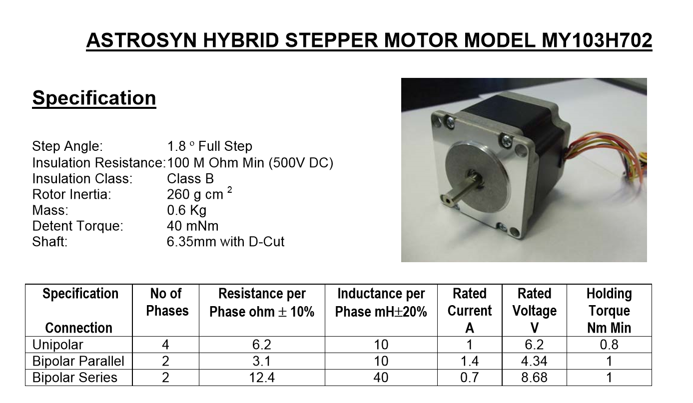
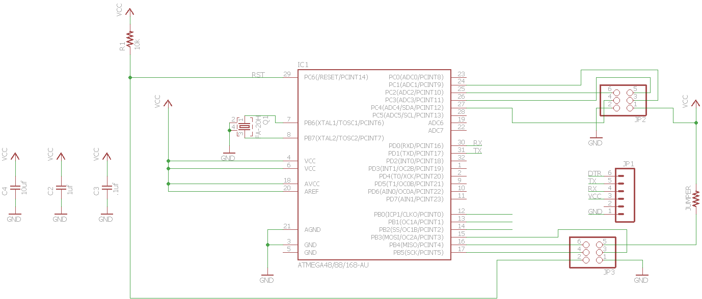
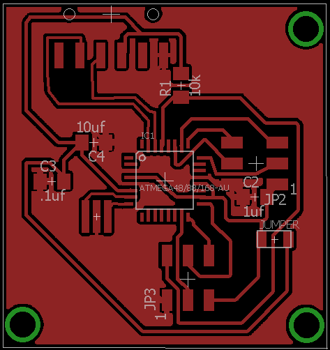
After some thought, I decided to separate the stepper controller modules and the MCU board, I can use these for my final project as well. I placed the boards to a 3D printed box. I designed the board using ATmega328p and used the same Arduino code for testing the stepper as above. I used the method of uploading the code to the processor described in week 8.
Here is the processor board.

Here is the board for the stepper controllers. The board needs to be mirrored when milled since this is through hole board

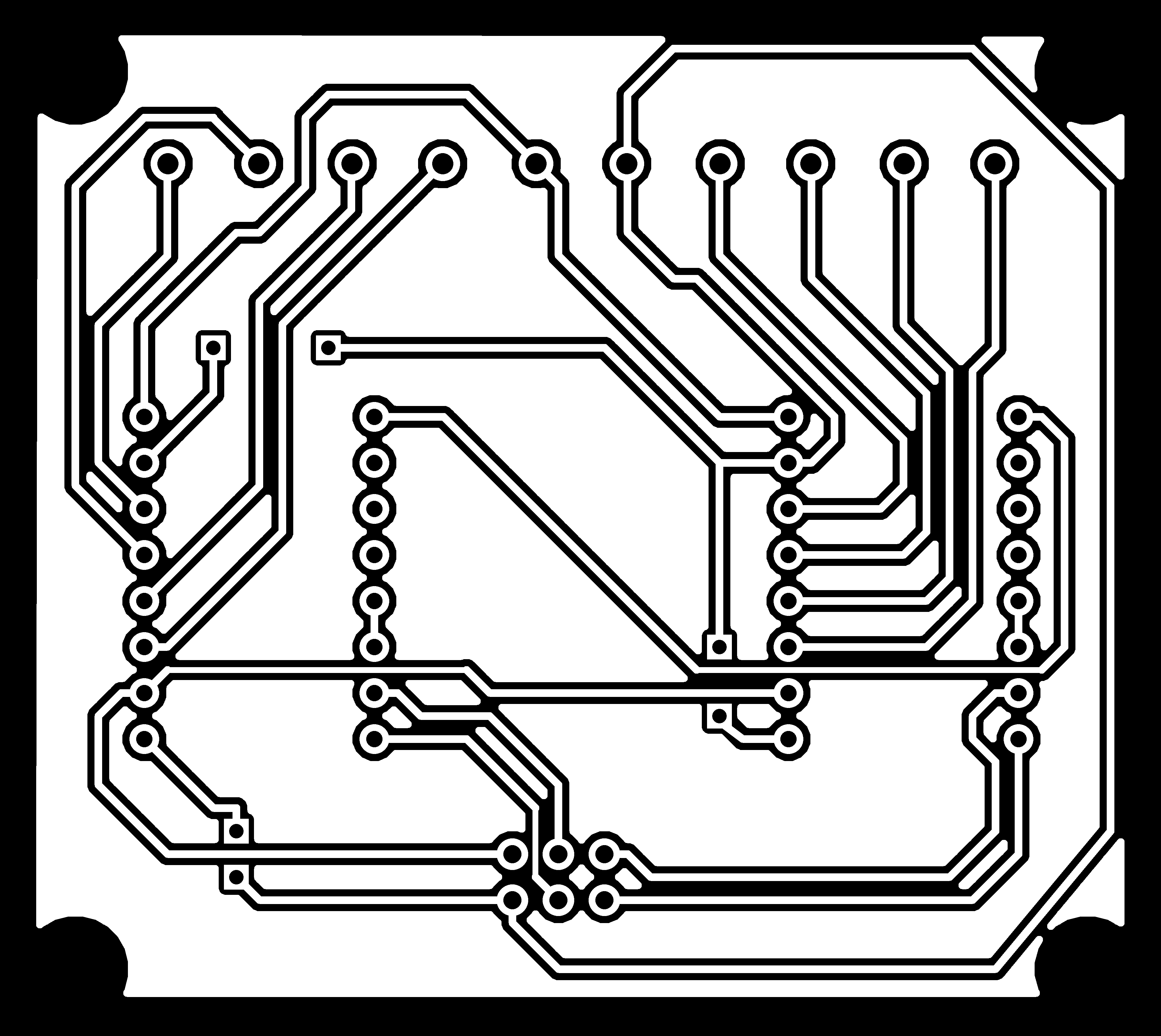
Spot the short circuit which is fixed on the bottom