Machine design and building
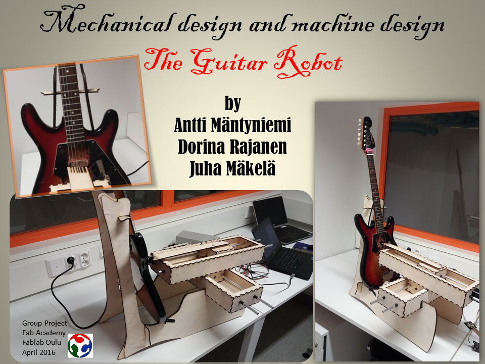
Guitar robot
We started the group project in Week 9 when the starting kit arrived on Monday. In time we come up with some ideas of what the machine should be: a writer, a pick and place system. In the end we agreed to build a guitar robot who plays guitar; this will be exciting!
As main documentation, we have used the tutorial provided by FabAcademy Getting Started With Gestalt Nodes and the description of gestalt machines here. On the way, we found also very good projects documentations at Fablab Amsterdam 2015 and Fablab Lisbon 2015.
Planning and execution of the project
Because the task was quite complex and the time so short, we did not use extra time to plan the project and assign tasks; we started with and completed different jobs as they were documented in the available online learning resources. In summary, the following tasks were executed:
- Fabricating the bridge board (Juha, Dorina)
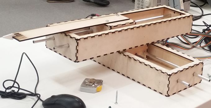
- Designing and producing the machine stages and frames (Juha, Antti)
- Testing the motors and python code (Juha, Antti)
- Design and make the end effector (Juha)
- Design and make the guitar stand (Dorina)
- Assembling the parts together (Juha, Antti)
- Code the machine and guitar riff (Juha, Antti)
- Documentation of own contributions (Juha, Antti, Dorina)
- Documentation of the group project (Dorina)
- Presentation files (slide and video) (Dorina)
- Video compression (Antti)
The detailed process is described in the following.
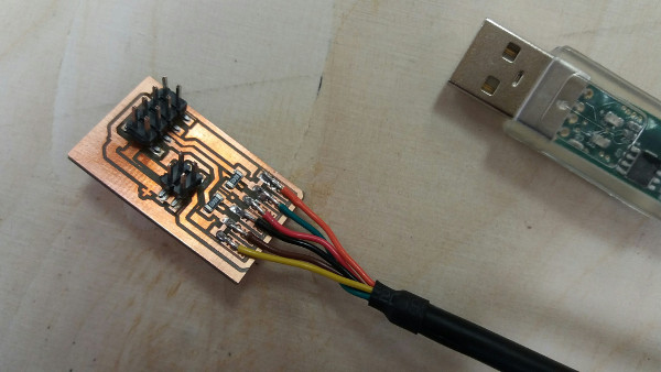
We started with creating a bridge board that adapts the FTDI RS-485 cable to Fabnet network. (see here); Juha and Dorina contributed to this task, by milling and soldering, respectively. Accidentally, I soldered an 8-pin header instead of 10-pin header on the board. Apparently this does not affect the system (the missing pins correspond to power connection, which is already defined by other 2 pins), so we decided to leave the board as it is and take care when connecting the serial cable to it .
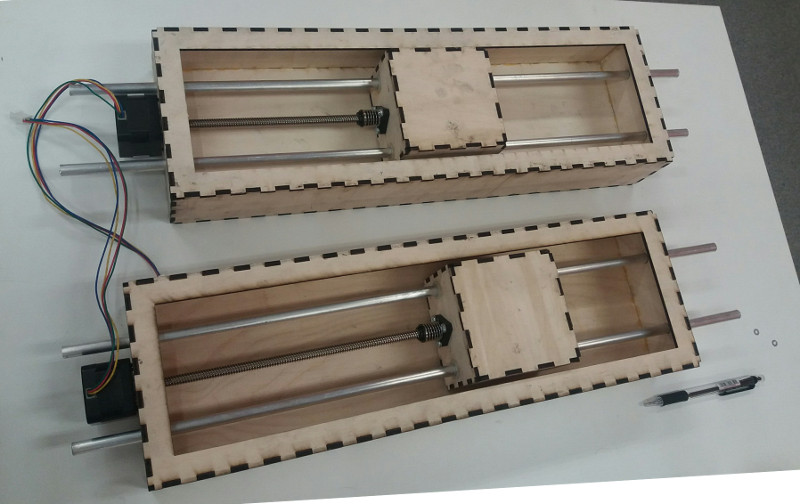
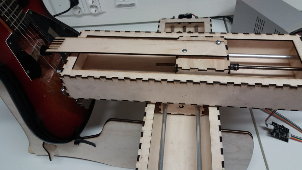
In the same time we prepared the stages of the machine; two stages are needed (see here). Juha has done different trials with cardboard based on the files provided in Rhino; the results were not satisfactory (they required glue and pressure to hold the parts in their place and we wanted a stable structure that works well without extra supporting materials). Thus we decided to make own cutting files in Inkscape and use plywood instead of cardboard. Antti has done a great job with plywood!
In week 10, we started the documentation of the group work. Dorina chose to do this task.
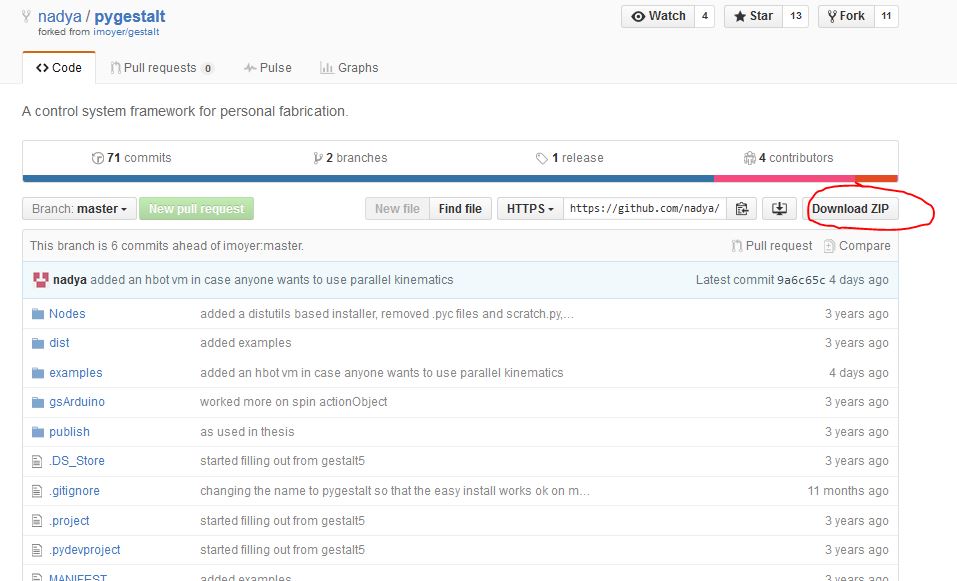
Then we tested the motors and the python code. We downloaded the python files from Nadya git repository (see here). We tried with both Windows and Linux, but without success. In Windows, the problems are when installing the setup.py program. In Linux, this operation succeeds but there is a problem with the FTDI cable driver. We will examine this.
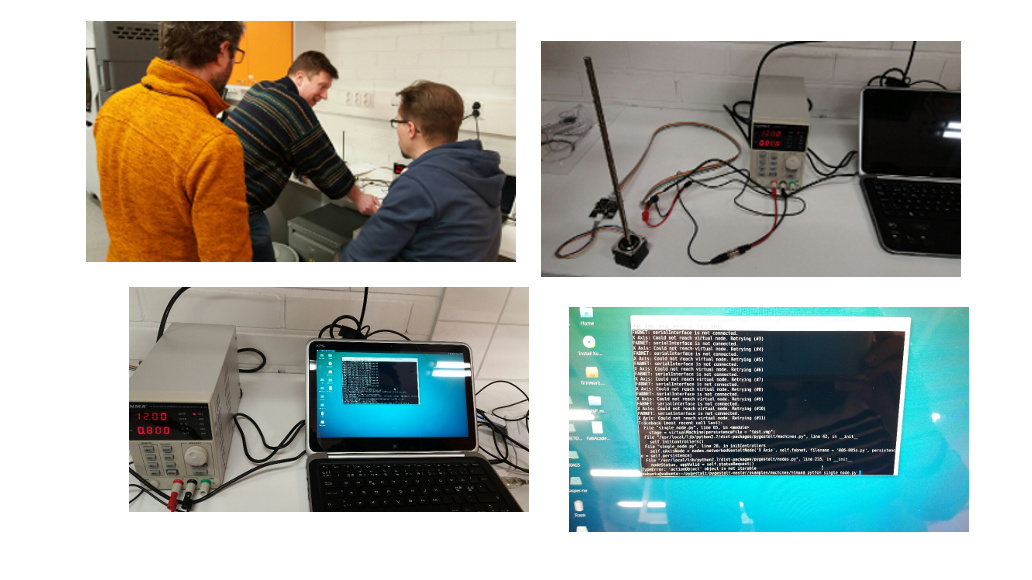
Next day, we tried again the python code to test the motors. This time we used Linux on virtual machine. It worked both the FTDI driver and the python code. We did not have to install the FTDI driver; it was recognized automatically. Also when tried on a Linux computers the system work perfectly now. The steps are the following:
- Connect correctly all the parts
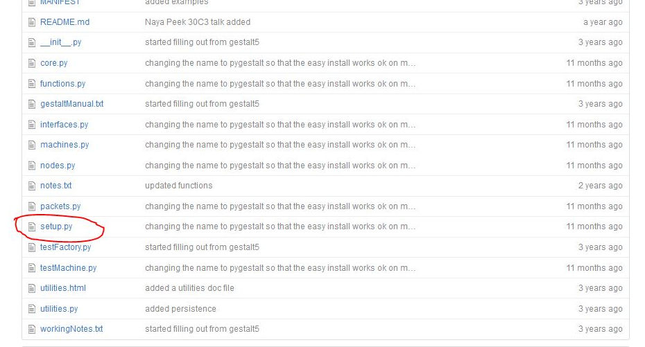
- Download the pygestalt code from Nadya git repository (https://github.com/nadya/pygestalt)
- Install the setup.py
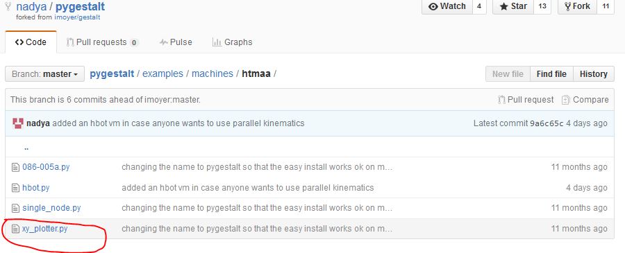
- Run the xy_plotter.py (found in examples/machines/htmaa)
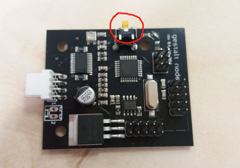
- If everything is ok, the two stages should now be activated. Before the motors start running, in the Linux terminal you are requested to identify the x axis and y axis. At this step, you have to press the yellow buttons on the gestalt boards corresponding to x axis and y axis, respectively. This notification is also shown on the boards by blue leds blinking.
sudo python setup.py install
For ease of use, in Linux terminal change to the folder where you have downloaded the pygestalt code.
sudo python xy_plotter.py
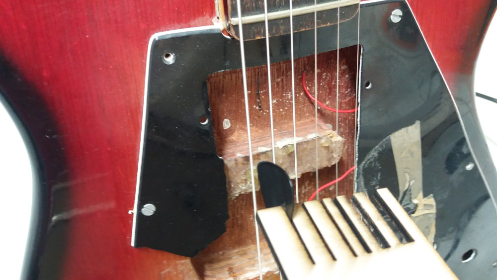
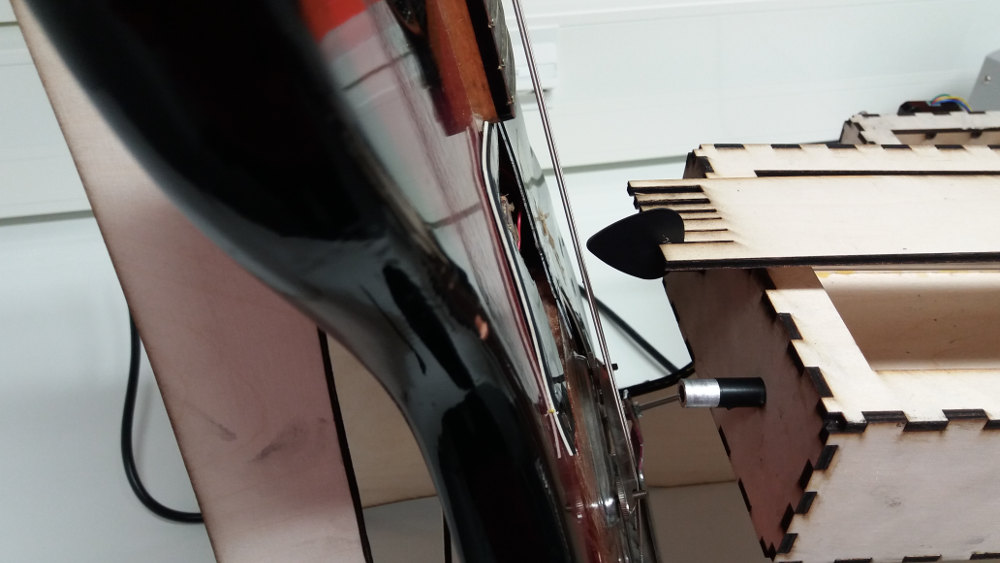
The next step was to make and assemble the end-effector: a piece that imitates the hand movement and can hold the plectrum. Juha has done this task. The end effector has slots of different sizes to fit different plectra and playing styles. See images below.
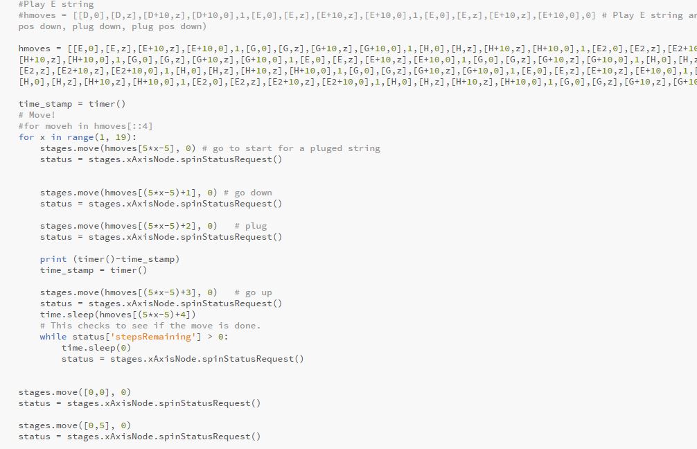
The next step was to code the machine movements and the guitar riff. Juha and Antti have done the major contributions to this task. Juha has done the coding of the machine movements and Antti has done the song composition. Dorina has assisted during the team work. The code can be downloaded here.
Some of the most relevant lines of code for guitar playing are the following:
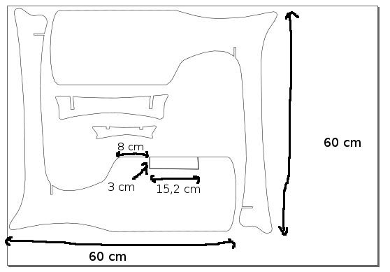
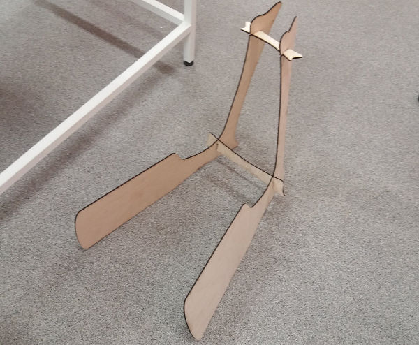
We also needed a support for the guitar and stages. Dorina has built a guitar stand using plywood and lasercutting, based on a model found online here. The design was not available online, so we had to create our own in Inkscape and adapted it for our purpose to fit the stages. The design files for the guitar stand are here.
The inkscape design is shown below. For each leg of the guitar stand, two parts were printed and glued. To accomodate the stages, we had to laser cut a groove in the extension part of the legs before gluing all the pieces them togeter.
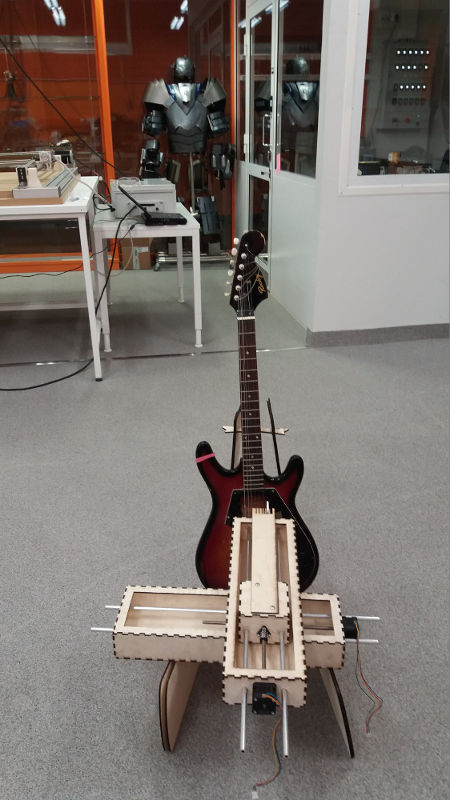
After gluing the parts of the stand, fixing the stages and the guitar on it, and programming the song we are ready to demonstrate how the machine works.
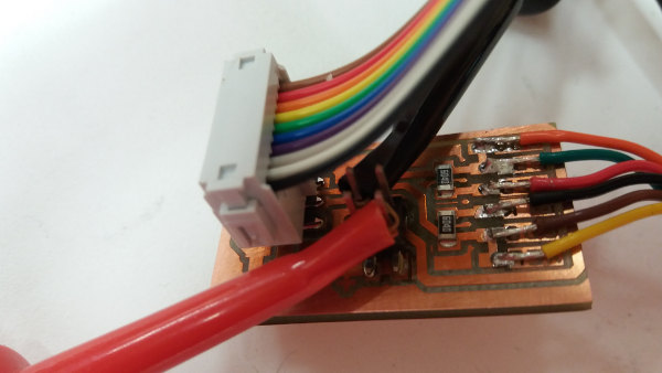
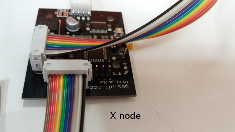
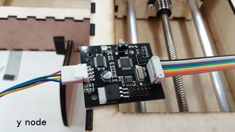
The pictures below show the cable connections.
The next step was to prepare the presentation slide and the demo video. This task was done by Dorina. For video making and compression, I have used Media Maker.
The presentation slide
The video (22 MB): https://drive.google.com/open?id=0B6jtgIKAJ0-AeVlSMXRjdFZhekU can be downloaded and viewed with HD.
Antti has compressed this video file (mp4) with the tool Handbrake video converter and resulted a file of 7 MB that can also be downloaded from here "Compressed mp4 video presentation (7MB)".
For more details in certain steps (stages construction, coding) see also documentation by Juha, Antti, and Dorina.
Problems and how they were solved
We had a very good team work and everything went very well. There were some problems with installing the gestalt nodes SW on Windows computers as described above. However, we managed to solve this problem by 1) installing Linux virtual machine on Windows, and 2) using Linux computers. No other major problems were encountered.
Future developement opportunities
During the live presentation in the class, Neil suggested with an example that the frequency of the stepper motor noise could be somehow also modeled so that it renders melodic tunes. This could be explored in the future. Also Neil suggested later during Antti's final project (kantelematic) that these fab instruments can be networked to form a robot musical band. Antti also plans to include wireless capabilities to his kantelematic (which is using servos instead of stepper motors) to allow remote communication with the microcontroller to play different songs.
Design, code, and presentation files
The following files are available for download: