This page illustrates in a narrative fashion my final project for the class and the project development. For the final project, I tried to incorporate as many processes as possible that I learned during Fab Academy to demonstrate my competence and aid in the creation of my project for my lab.
I will address the following:
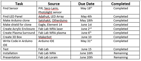
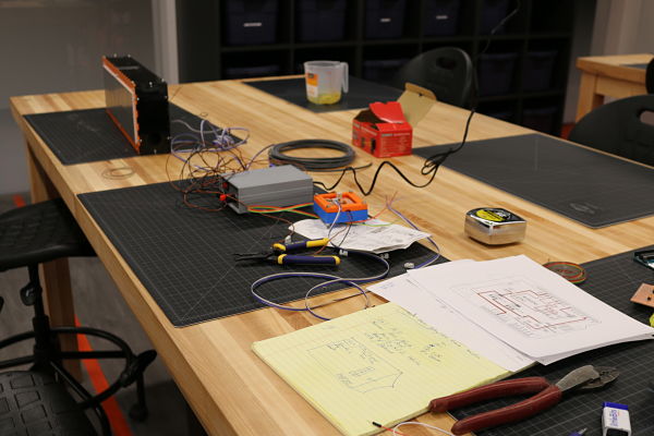
I set up a schedule as recommended by Neil and Scott, our local lab instructor, for self imposed due dates. I needed to stay on course because I work full-time, am setting up our school FabLab and have family. I need to hit all the proposed dates to make sure I complete my project on time, plus stay up with the weekly assignments in class. This schedule is extremely helpful as a reminder of how to be diligent and stay on course to finish the project on time. In fact I have hit a few earlier than the target date based upon my time available to work on the project. I know I have to present to Neil and the class on June 20th. I want to have a finished project to demonstrate. I worked each weekend on the project and used many late nights to achieve my project while staying up to date on the course. I also had the added pressure of showing off the People Counter in our lab and I knew it would be prominently displayed. I was working at every free minute to achieve the project. My teaching schedule also eased up with graduation so as you can see in the table, I worked more after June 1st. This was stressful as I had only a few days left and much could go wrong. I have learned much working with electronics that it can go wrong, so it is a gamble with only a few days between my test and presentation. I remember Neil in one of the first classes saying, "you won't get it all done!" I think that I have lived this each week in the class. I needed the following schedule to keep me on task and get everything completed by the final day. I will complete the following tasks the last weekend by installing it on Friday and taking the pictures and movie of it in action. This gives me a weekend, in case anything does not work, but I will have a conceptual model. I did get it tested and it works. I still have to install it, but that is easy as I have a construction background and find installation of wires easy. The presentation needs finished up as well. I have struggled a bit on making the shield as I had some issues with the power jack and regulators. This took longer than expected to resolve. I also spent alot of time getting the wiring headers working correctly.
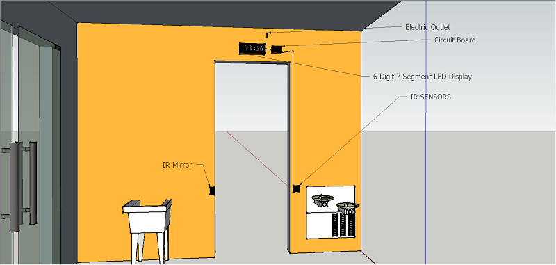
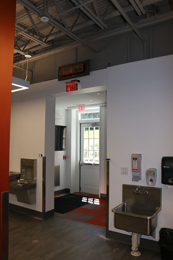
I want to create a people counter at our FabLab. I get many questions from administration and interested outside parties about the attendance and usage of our lab. This is a natural question with the investment in capital for the FabLab. I decided a visual people counter would clarify any questions that anyone had about usage for our lab. We have a main entrance that all visitors would enter through to use the lab that I illustrated during Week 2 for Computer-Aided Design
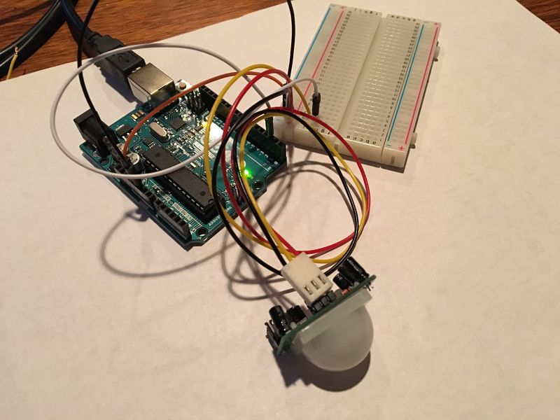
I started the process of creating the people counter by trying a few different sensors. I looked at lasers, PIR sensors and a 5MM IR break beam sensor but nothing could span the 61 inch opening of the main door consistently and accurately. This process is documented in Week 17: Digital Fabrication Applications and Implications
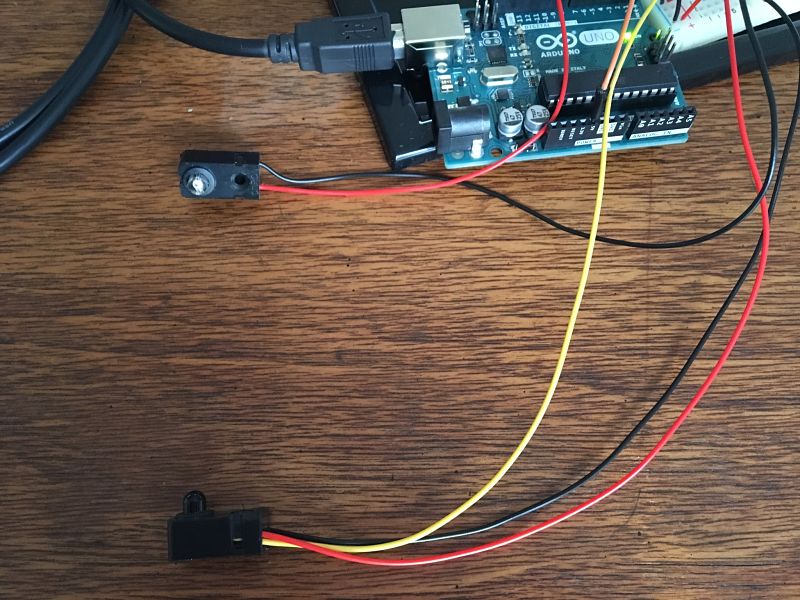
I ultimately decided to use the Seco-Larm reflective sensor as my input device. It had an advertised range of 35ft and ran on 12 volts. The sensor also only had one cord that would be run down the side of the doorway. Many break beam sensors have two cords that would have to be run down each side and I did not want the clutter. I was going for a minimalistic approach and this input device works exactly as I would need.
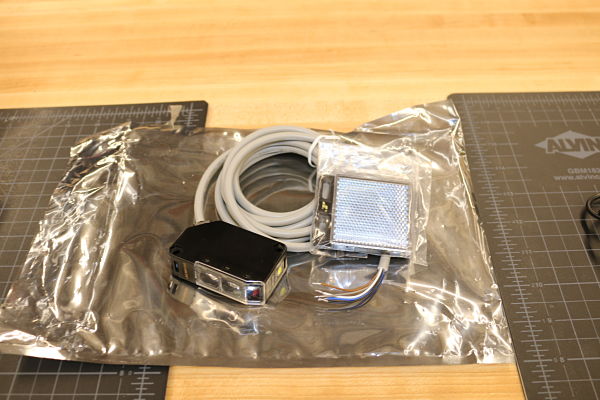
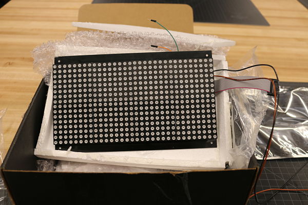
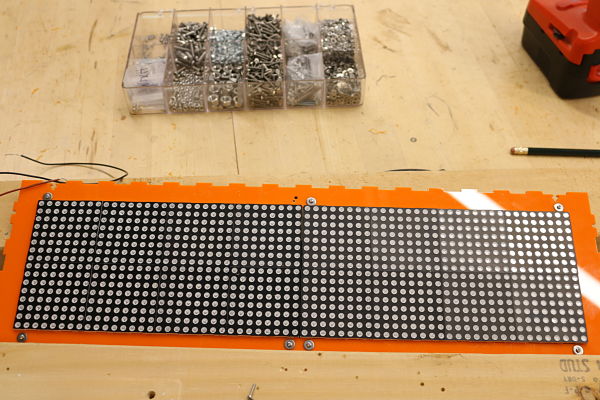
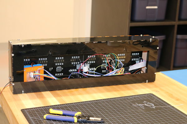
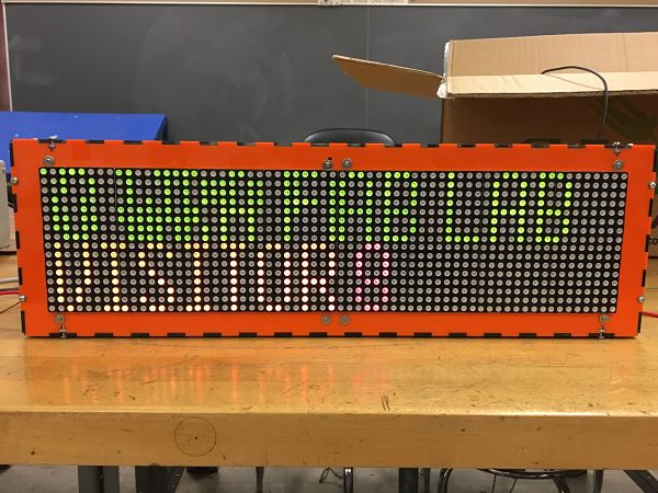
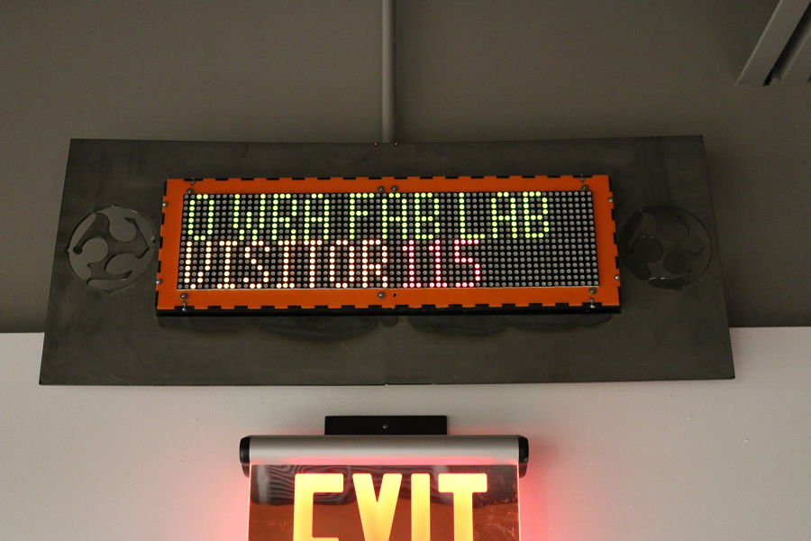
I then decided to use two 32x16 red green dual color LED Dot matrix screens as my output devices. These are 5V and provide the necessary screen size to be able to read the LED screen from a good distance. It was also more cost effective to purchase the LED panels than build the LED array. They also have good Arduino libraries to support the display. This made the integration easier for the output device. These screens also allow to scroll a message with the output and provide good variety for the end user. I purchased two and connected two panels to provide the sizing I needed for my sign.
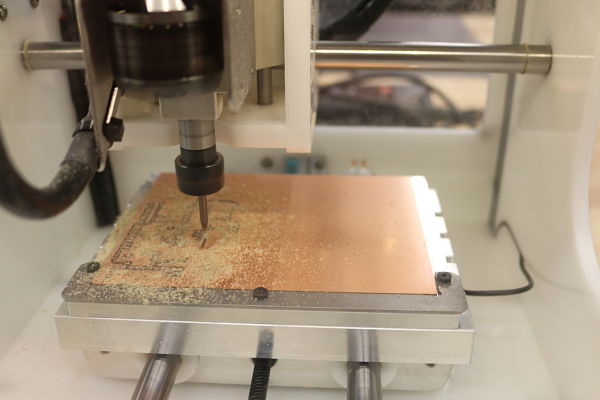
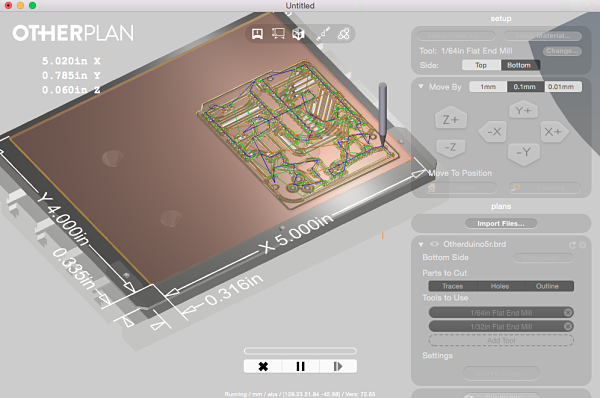
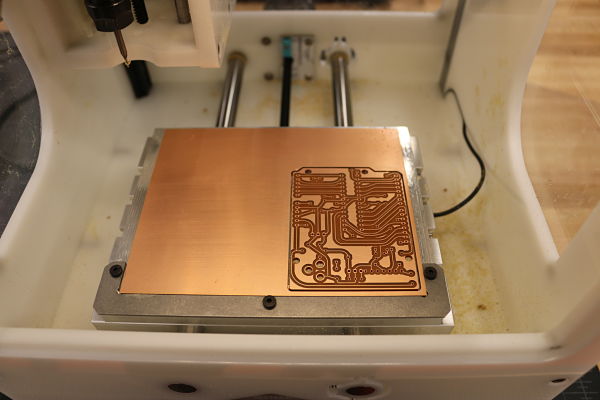
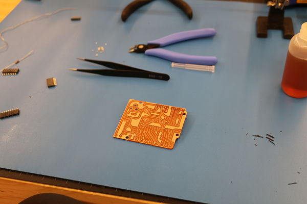
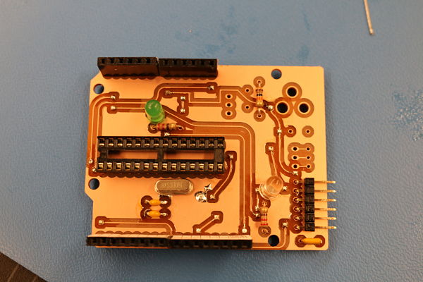
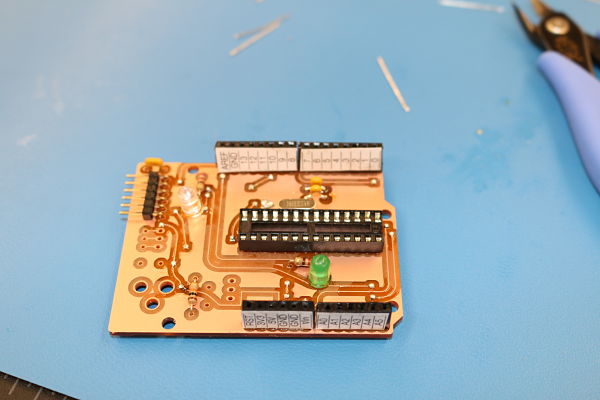
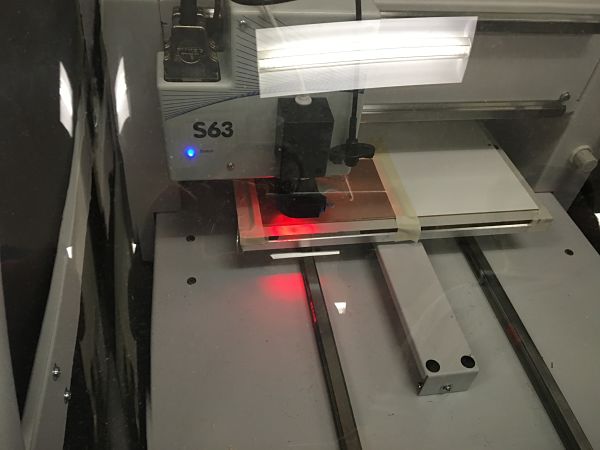
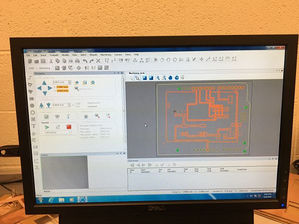
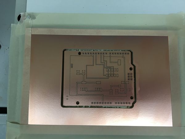
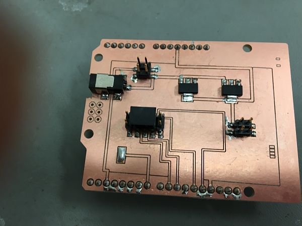
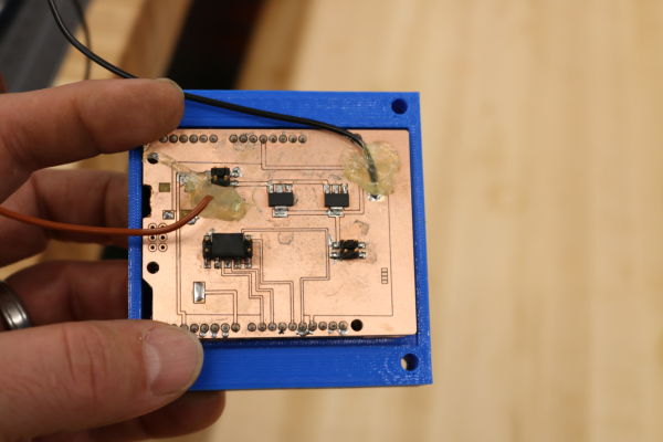
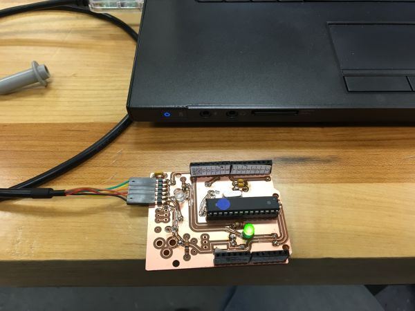
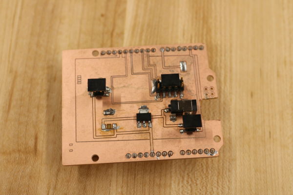
I then decided to create an Arduino based board. I had purchased an Othermill for our lab and decided to mill the Otherduino board and create the Otherduino. I milled out the board on the Othermill. I then populated the board with the components and the ATmega 328 microcontroller. The board is a double sided FR1 board with through hole soldering and vias. It was a challenge to get the board created and soldered. I was used to surface mount soldering. I actually prefer surface mount after my experience in the Fab Academy. I choose the Otherduino as I was going to manufacture a shield to attach the components. All the other created fabbable Arduino boards like the Satshakit were not as easy to fabricate a shield for. I used OtherPlan as the CAM software for the job.
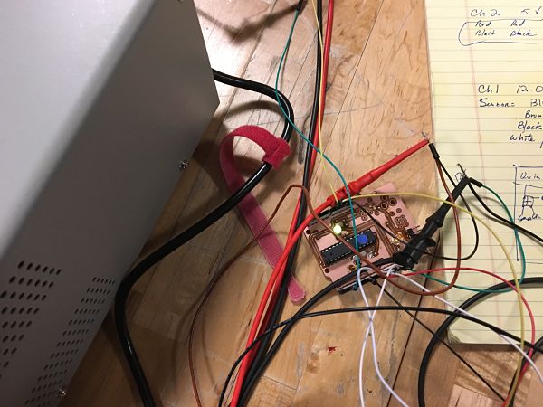
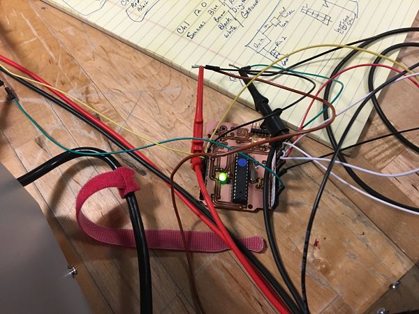
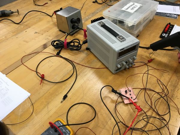
I then decided to hook up the Otherduino and hook up the inputs and outputs to determine if I could get the Otherduino to do what I needed before I created the shield. As I expected, it was a mess of wires and I needed both a 5V supply for the outputs and 12V for the inputs. I then started the code for the Otherduino to count people as they entered they would be counted, but not when they leave. I then finished the programming to only count a person once when they entered. I hooked it up to a dual power supply for the different voltage requirements and started the process of working through what worked. It was a mess of wires that needed cleaned up with a shield that I would make.
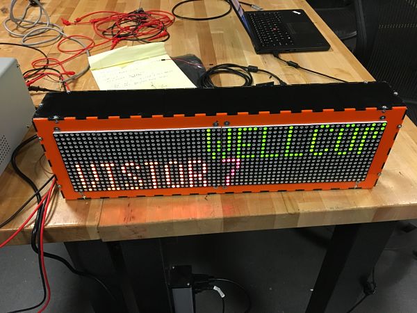
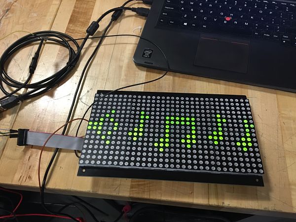
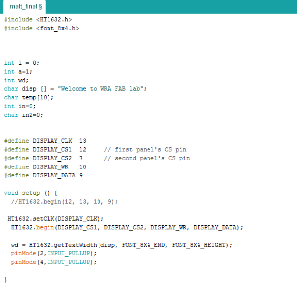
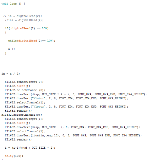
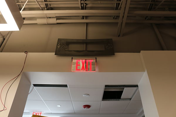
I needed to write the code for the Otherduino and sensors to display on the LED screen. I installed the HT1632 Libraries for the LED screens. This allowed for me to display to the screen. I then needed to be able to count people entering the room only once. I played around and found that if a person stopped in front of the sensor, it would just count up continuously. I fixed that with the digitalRead command Low. If they stopped in front of the sensor, it would not count them until they moved out of the sensor. I did not want students stopped in front of the sensor and it counting. I also have it counting them only once if they come into the room. It will only count every other time the sensor is triggered. This is indicated in the in= a/2 code. I #included the libraries HT1632.h and font_8x4.h for the display. I added the values and defined the inputs. I then set the disp or Welcome To WRA Fab Lab and the second line Visitor and the number of pixels to display. I started it on line 2 and 8 pixels high. I knew that if a person left by the back emergency exit it may not count them, but it should do a fairly accurate job of counting everyone who enters the room. I finalized the code and everything worked as expected.
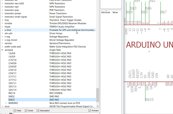
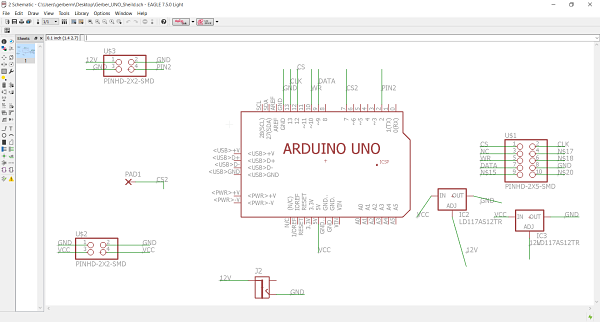
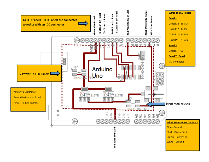
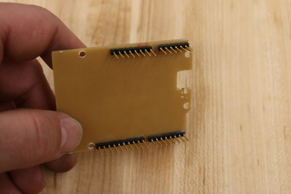
I needed to make a shield for the Otherduino. I decided to download the Arduino library for Eagle and the Uno. I uploaded the library to Eagle for the schematic outline as I planned my shield. I was going to need to regulate the power, one two x two header to power the sensor, one 2 x 5 header for the outputs to the LED, one 2 x 2 for the power to the LED, two 5V 1A regulators for the 12v and 5V inputs and outputs, and power. It was a simple design to clean up the wiring mess and eliminate two different power requirements to the project. I created the first shield and had some issues, which I will describe later and then created a second shield which was not perfect but works.

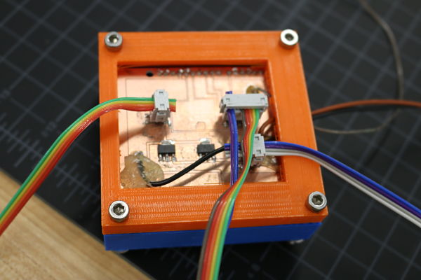
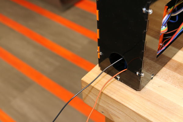
I hooked up the electronics based on the schematic I made. I created my own diagram to follow to hook everything up on shield. The diagram is the shield and it plugs in or is snapped down onto the board. I wanted to create the shield to make it easier to hook up the wires. I did find that I probably should have used screw terminals but the headers also worked. It was difficult to get the low voltage wire in the correct header pins. I stuck to the diagram I made by hand initially and then cleaned it up to carefully show how it all hooked up.
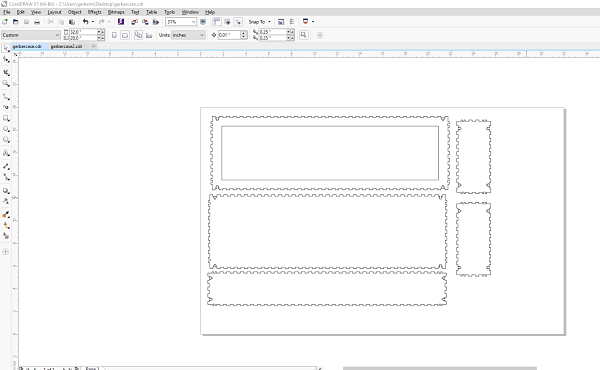
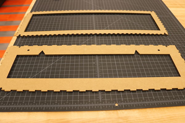
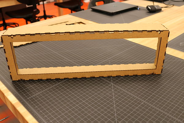
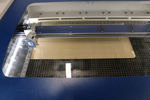
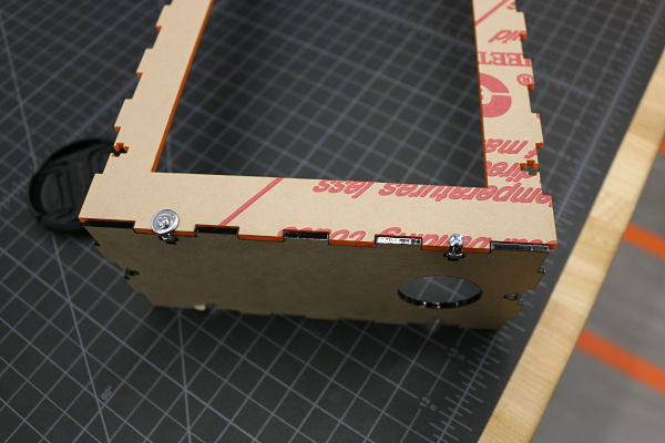
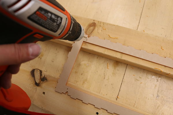
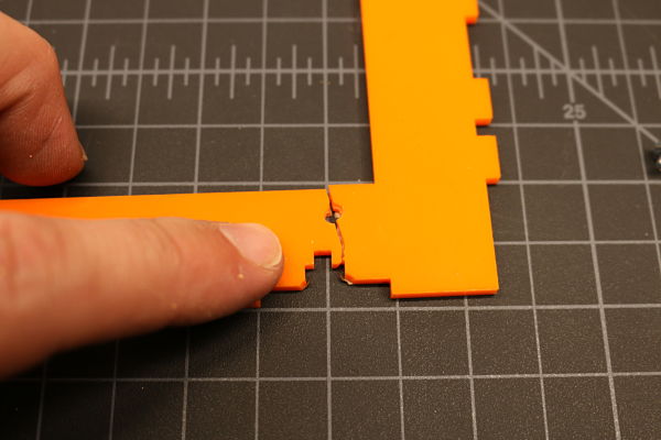
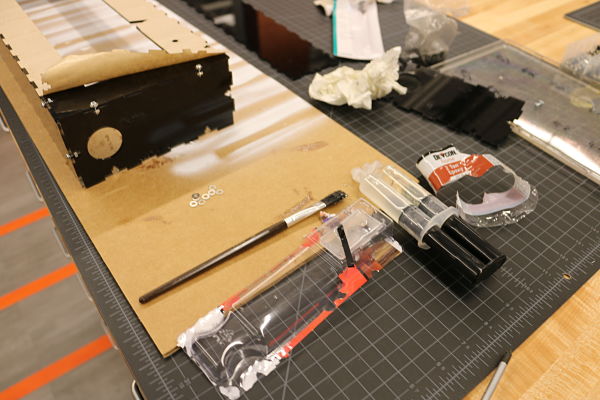
I needed to make an enclosure for the LED screens. I decided to make it out of acrylic and use the Epilog laser cutter to create the box that would wrap around and hold the two LED screens. I first decided to create the box using MakerCase. This was a very quick way to create a box using T-slots to join the box. I intended on using screws to hold the box together with some expoxy. I put the general dimensions into the MakerCase cloud based software and exported my box. I then imported it into CorelDraw 7 and added the front cut, back cut and hanging slots. I decided to cut the box out on cardboard as a cheap prototype before I committed to cutting it out on acrylic. This proved to be a great idea as I increased the tab width to provide it a better look and fit. I then put the LED screens inside the cardboard model and it all fit they way I wanted it to. I then proceeded to cut out the final model. As I was cutting out the final model. I had to drill the holes to attach the LED screen to the acrylic. I cracked the first attempt and had to recut the face. This was easy to do and the second face worked. I then used acrylic glue to fasten the pieces together. I then screwed the LED screens into the enclosure and ran the wires out the side.
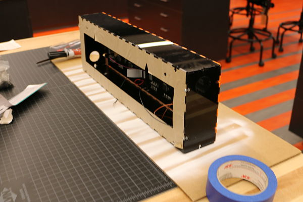
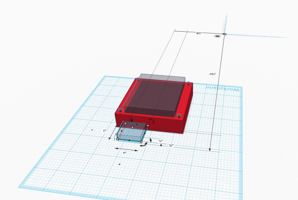
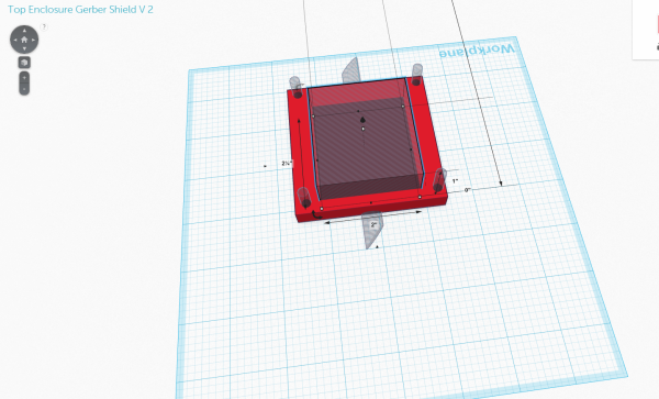
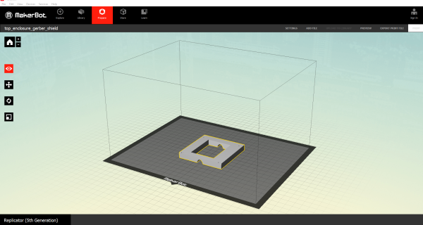
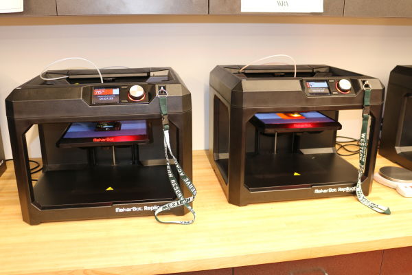
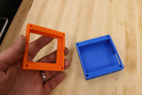
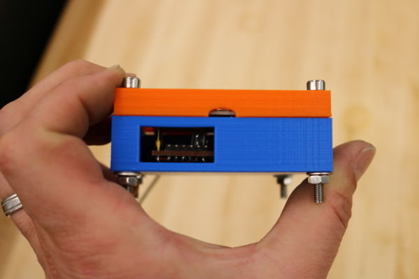
I then needed to make an enclosure for my Otherduino and shield. I decided to use another process and create a 3D printed model to enclose my shield and Otherduino. I decided to use Tinkercad to create the .stl file needed. I just needed a quick box and access for my FTDI header and the top shield connectors. I created an upper and lower that was attached by four machine screws. It needed to be small enough to fit into my acrylic enclosure to hide the shield and enclosure. I exported the .stl files and printed the upper and lower enclosure on the 3D printer in PLA. I did create several versions to get the correct fit, but will discuss that later.
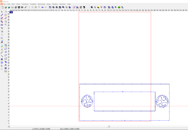
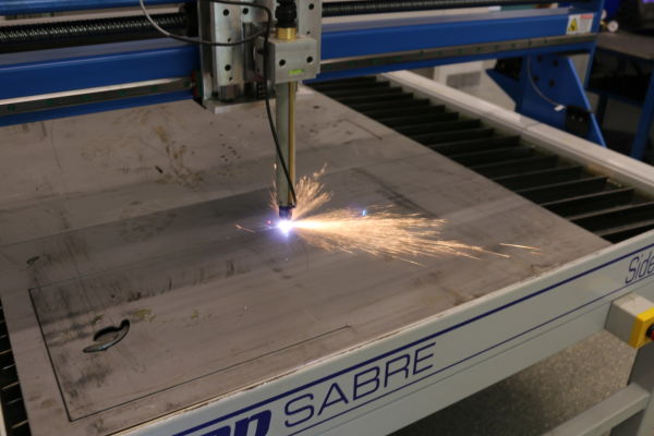
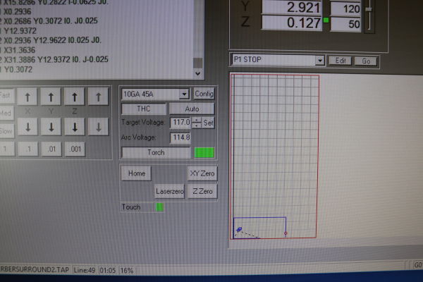
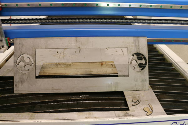
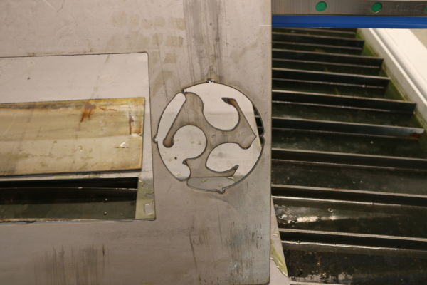
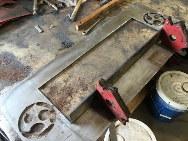
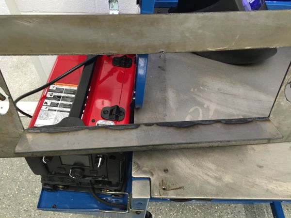
I also wanted to use our CNC plasma cutter to make a metal surround and then weld a shelf on the back to hold up the acrylic LED box. This would demonstate my understanding of two other processes: CNC machining and materials joining (welding). I opened up Enroute and build my surround. I imported two Fab Lab logos and then vectorized the logos in Enroute. I then created a 10 guage metal surround and used the ShopSabre CAM program to machine it. I set up the job settings for the plasma including the entry/exit angles and voltage. I entered at 90 degrees and left at 45 degrees. I was running 117 volts. It was a relatively simple process. I then used the plasma to cut the insert in half creating a 3 inch strip that I welded on to the back of the surround to hold the acrylic LED screen in the surround. It turned out well except for the burn marks when I was welding it together.
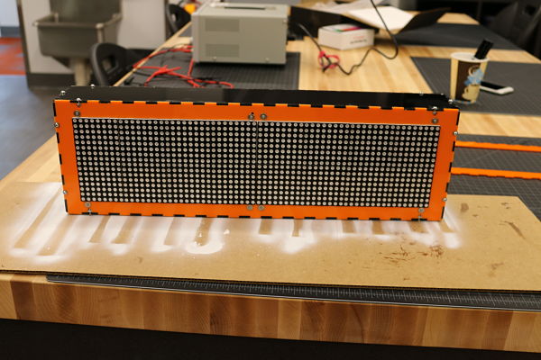
I needed to test the sign and took it to the lab and had a student walk back and forth to see if it would work as designed. As you can see it does count appropriately. This was a great sign as I was getting closer to putting everything together.
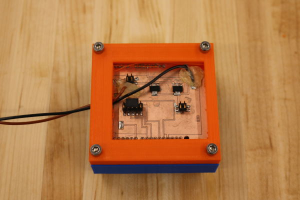
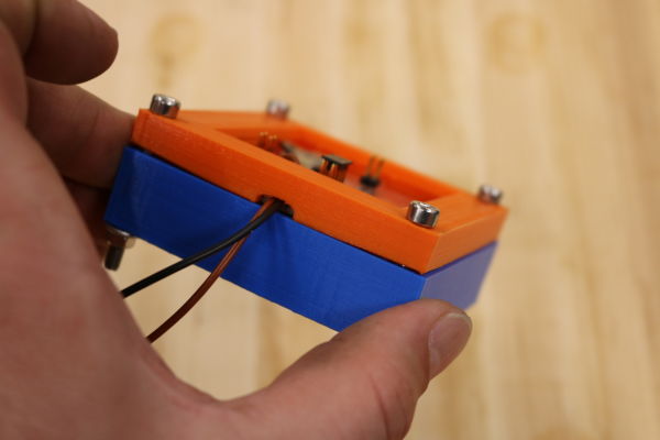
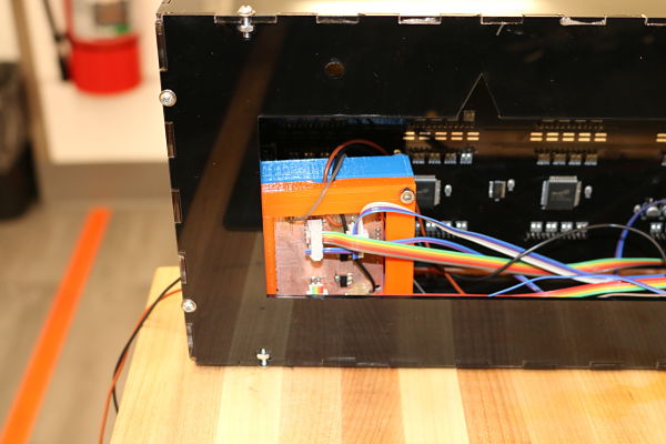
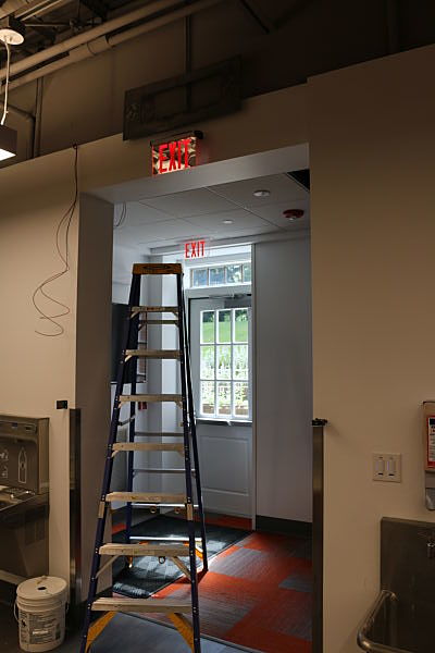
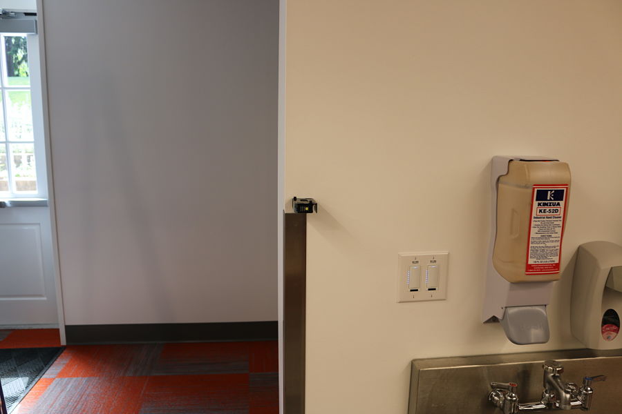
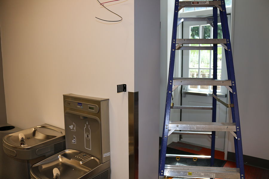
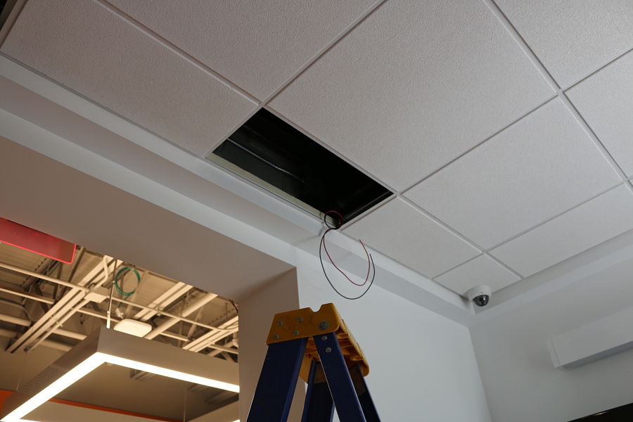
I decided to put together the sign. I attached the shield to the top of the Otherduino. I then carefully placed it inside the 3D printed enclosure and screwed the bolts together to hold the enclosure together. I made several serial cables to run from the sheild to the sensor, led and power supply. I was careful to make sure, using the schematic, every cable ran to the appropriate place. I also needed to make sure it was well grounded. I set it up and made sure it was working and then placed the 3D enclosure inside the back of the acrylic enclosure. I ran everything as neatly as possible checking all my connections to make sure it all worked. I then drilled the metal enclosure to the top of the ledge above the door. I then drilled a hole in the wall and attached the sensor 54 inches above the ground. This should hit most visitors chest when they enter. I fished a line up the wall and pulled the wire out on top of the wall. I then set the acrylic enclosure on the metal enclosure and ran the wires. I hooked up the sensor to the wires from the shield. I installed the power supply in the false ceiling and plugged it in to the 110v outlet. I drilled a hole between the walls and fished the power wires through the wall and hooked them up to the shield. I then set the acrylic box inside the metal enclosure and put a small shim on the top of the box to ensure it did not lean forward. It was a 1/8 shim of acrylic. I then turned on the power supply and it all worked like it had on the floor before I installed it off the ladder. I was satisfied because this was the finished product and it looked and worked well.
The major issues I had during the process of the design were:
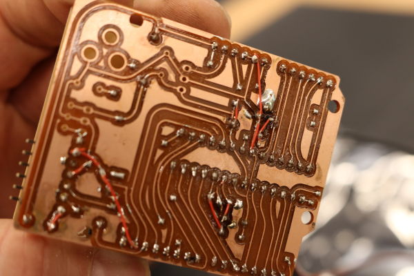
The Otherduino board did not work after I cut the board. I soldered and added the vias to the board and I could not get the simple Blink sketch to work. I took it into the lab and used the microscope to see if any traces had come up or any other issues that were present. I did a continuity test on each path to check and found I did have traces that were an issue. I decided to solder a jumper wire on to the back of the board in two spots. This helped fix the issue with the Otherduino. It is amazing that you can relatively easily create your own Arduino based board. I wanted to create the board as I may have my students next year create their own boards. I did get it up and running, but as I learned with electronics, it can be awhile to determine what was wrong.
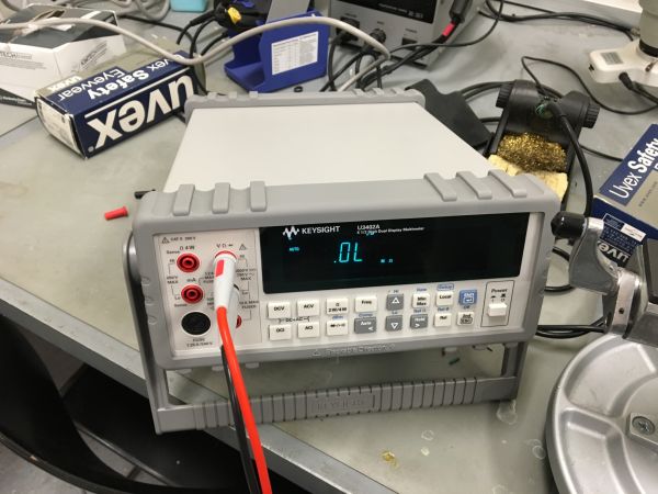
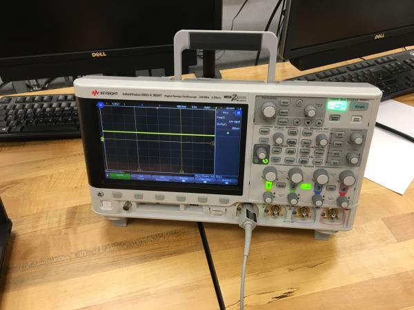
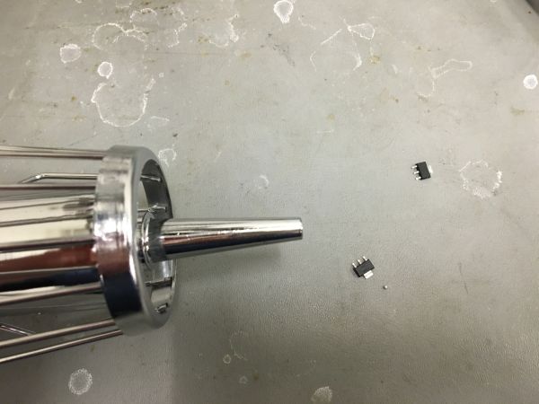
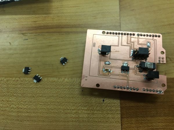
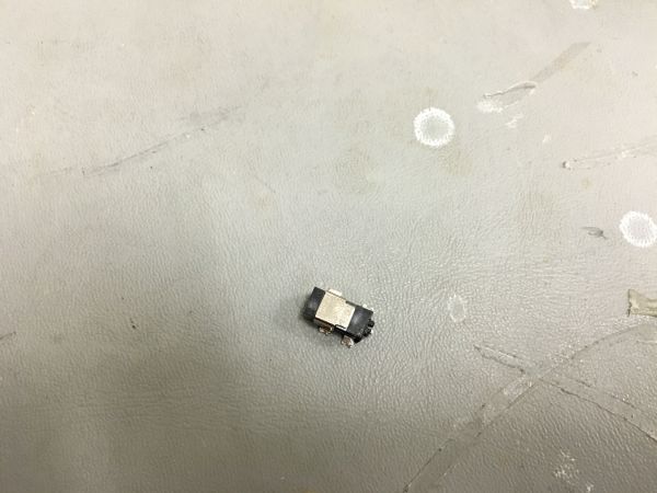
The shield presented a few issues with the voltage regulators. I created the first shield and noticed that the voltage was supposed to be around 5V. I put two 5V 1A regulators on the shield to deal with the issues of the 12V sensor as I only wanted one power supply to power the display. I noticed that the regulators did not work. I then checked each part on the oscilloscope to determine the issues. I ended up replacing the regulators. I even checked the data sheet to make sure I had everything wired correctly. I then with two new regulators could not get it to work. I then also had to remove the power supply on the board as it would not seat correctly with the input. I took a Dremel and carved a small opening for it to be on. I also used the heat gun to remove the regulators and replaced them. It still did not regulate the power. I decided to cut another shield and soldered two new regulators on the board. I used a third different type of 5V 1A regulators and these worked in keeping the voltage around 5V with the 12V power supply. I then had an issue with the power connectors on the board. I finally had to remove them and directly solder the power to the shield. I then hot glued these to the board to keep the wires from being removed. In the end I went through two shields and three different regulators before I could get it to work. It was an exercise in persistence.
I learned a tremendous amount through this process. I learned a great layout is critical for what you need to do. I had a plan for this since the third week of Fab Academy. I knew this was something I needed to try and build and in my first few class sessions I did not think I would be able to pull this off. I learned a tremendous amount in this process about 3D design, electronics, programming, milling a PCB, Eagle, welding, plasma cutting, laser cutting, voltage and much more. This project also allowed me to better understand time management in fabrication. It takes longer and with multiple failures to get it right in most occasions. This is one of the benefits of this project is that many times it needed to be improved and multiple prototypes are needed. I learned that electronics can be really frustrating because it sometimes does not work the way it is designed. This process was fulfilling as I was able to create something for my lab that is beneficial to our school. I learned about electronics, Eagle, PCB milling, C programming, welding and cnc milling in the process with much greater depth and understanding.
I plan on consistently working to improve the people counter. I would like for it to cache its memory in the event of a power failure. This way I would not have to start over at 0 and it could remember how many people had entered the building. I also would like to have it transmit the data to me via a cloud based connection. This would be extremely helpful to the build. These could be added in the code and by creating a new shield that incorporated memory. I am not satisfied with the final build and can improve on it in many ways. I would also maybe add LED lights and acrylic behind the Fab logos on the metal surround. It would be a better look to have the Fab colors illuminated by LED lights.