Modelling MyOrthotic
Design based on 360 fusion
Design based on 360 fusion
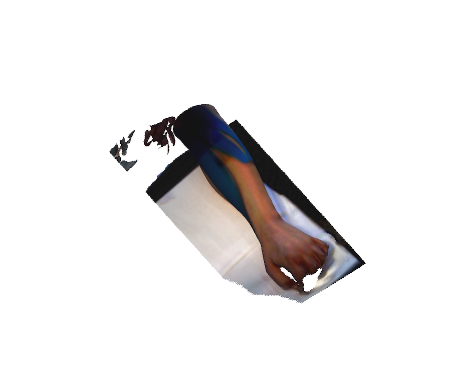
Scan I use the Sense scanner because, this scanner can do in a quick and simple form the construction of the mesh. Due to the condition of the patient he can not hold or extend the finger for a long period of time and this scanner provides a good result in a short time. First of all, I did the test with the forearm in the top part of the arm using, thinking in the design of the palm splint, I changed a little bit the idea making the splint in the back side of the hand, and for this reason I did a second 3D Scanner of the hand. Meshmixer: After first step was to scan the arm of Mr. Miller
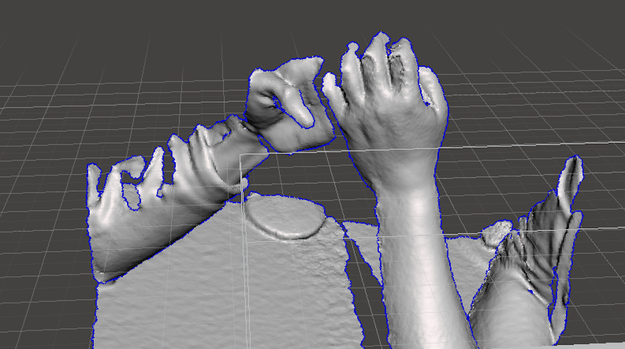
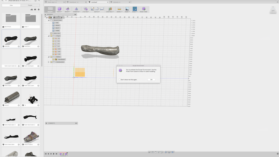
I proceed to edit the scanner in meshmixer Deleting and improving the mesh. Some of the common useful functions are: Select> transform: you can find the function offset the mesh, in this case to leave a space for the textile between the skin and the splint. Edit> cut plane: for better orienting and cleaning the model quickly. Edit> make solid: for making closed bodies, in my case I had to close the mesh. In order to get better results in the edition of the model I converted this in a free form in 360 Fusion. Analyse> Inspector : This is a great help to analyze the form and close the hold mesh in case of some errors in the original scan. IMPORTANT: In fusion you don't have the possibility to make offset of the objects, only scale or thicken, which are different functions in case of adding a material, in my case the textile for the orthotic. You have to consider this issue before working in Fusion and editing it in a mesh editing software. 360 Fusion: Import the 3D
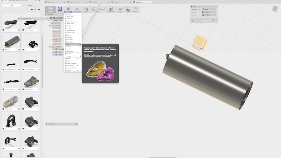
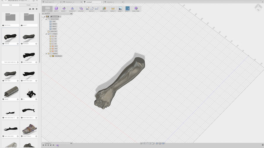
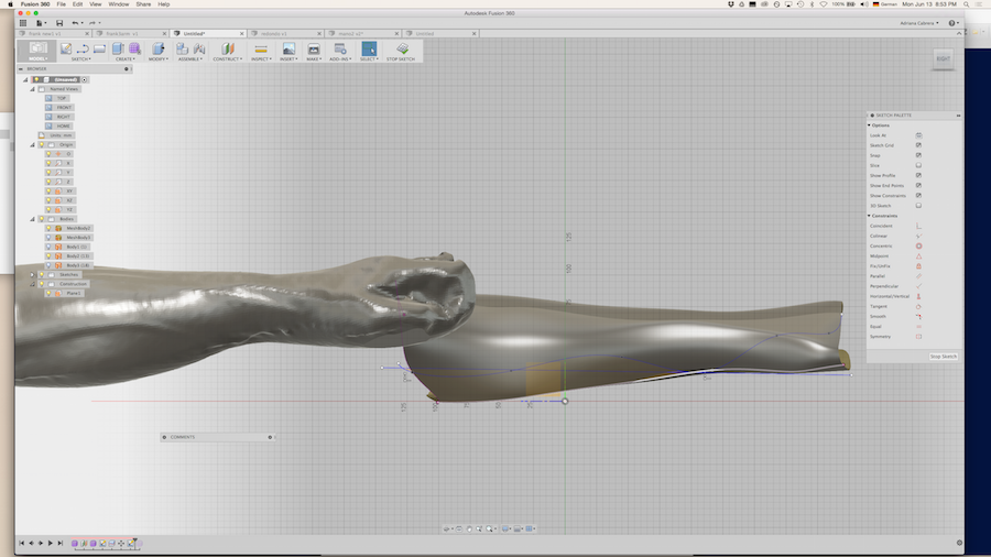
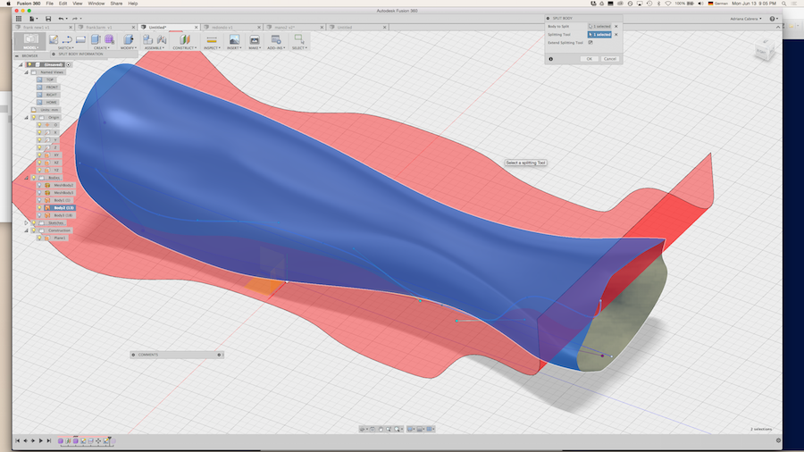
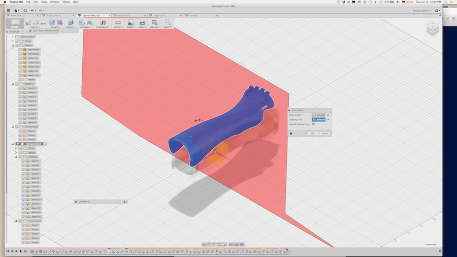
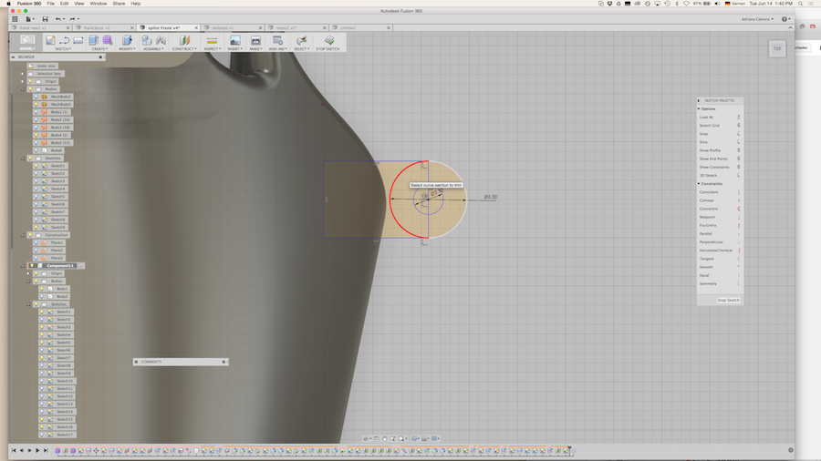
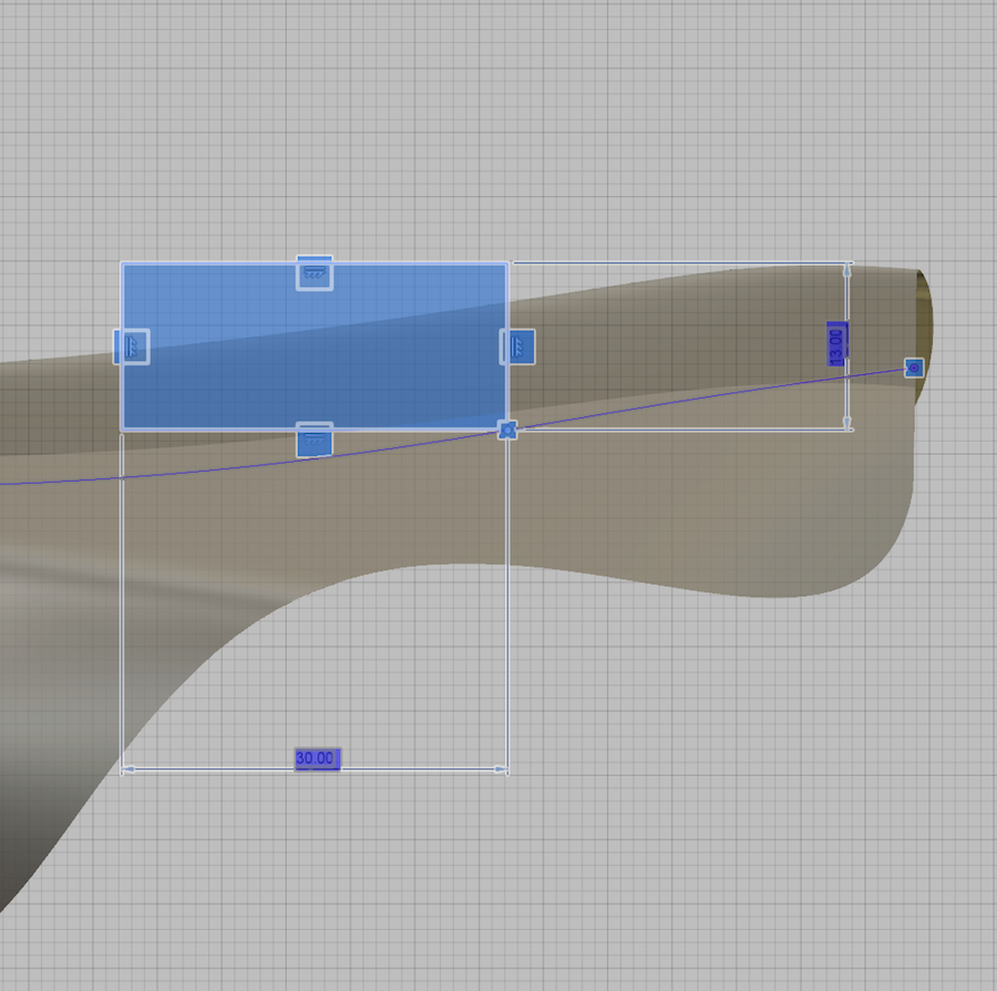
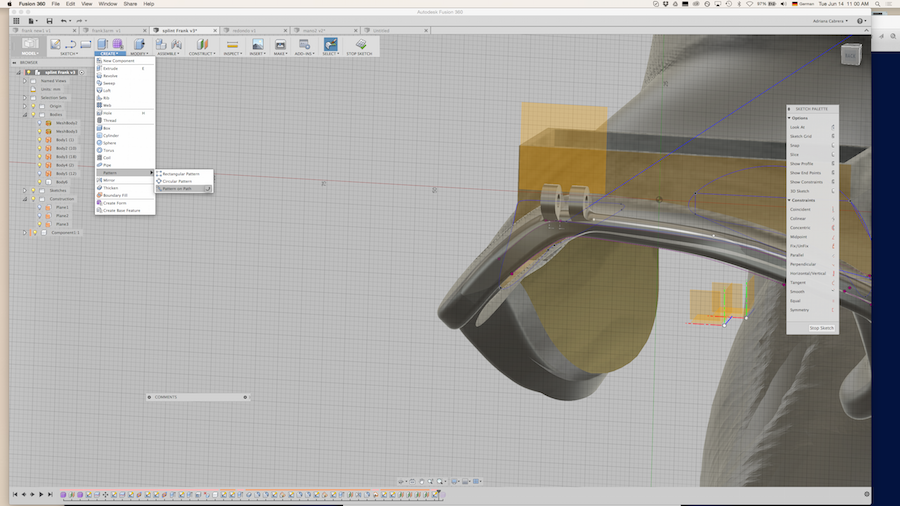
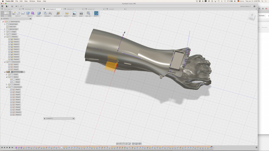
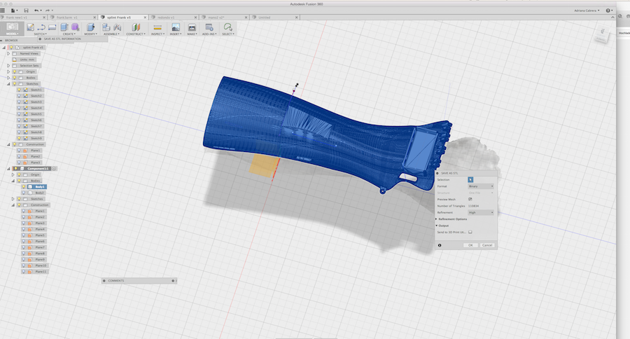
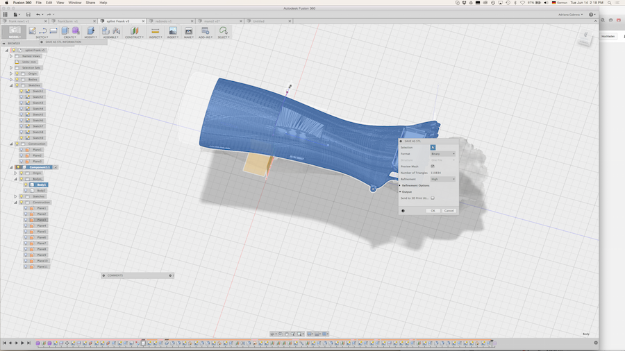
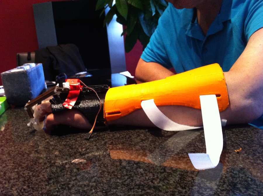
MODEL using the free form panel > insert > Insert mesh: it permits to import the model in the original scale and also select the units of the model. In Fusion you can find the function Free Form for editing the 3D Scanner and create a Free Form with the Scanner I use the tool: PULL. This tool creates a mesh of nodes in X and Y direction which is attached in the original 3D Scan. You can edit this form and combine it with other solids in order to do your model parametric. The free form function is not so much parametric, but it permits to edit the scanner in a better form. After finishing the form, you can return to the panel of the solids selecting the solid tool. It is total parametric, and you can recording the design History , in case that you want to change the parameters afterwards. After this construction, I did the editing of this for cutting the solid with a splint plane. In order to add more solids I recommend to place planes in order to have a better orientation. I did a plan for positioning the electronics, and also to make the container of the motors. I did the joints of the fingers, using the “pattern path tool” making the for and connection with nylon screws with a 3 mm diameter. Clearance : 0.2 mm For printing in ultimaker. The thumb joint is thought in the way, that it will have the movement in a perpendicular position, therefore the plane is in an offset in Z axis. When your splint is finished you can select the body and export it. In case that you have different bodies, you have to select the root of your data on the browser, deselect the part that you don’t need and export the STL data as a one body.
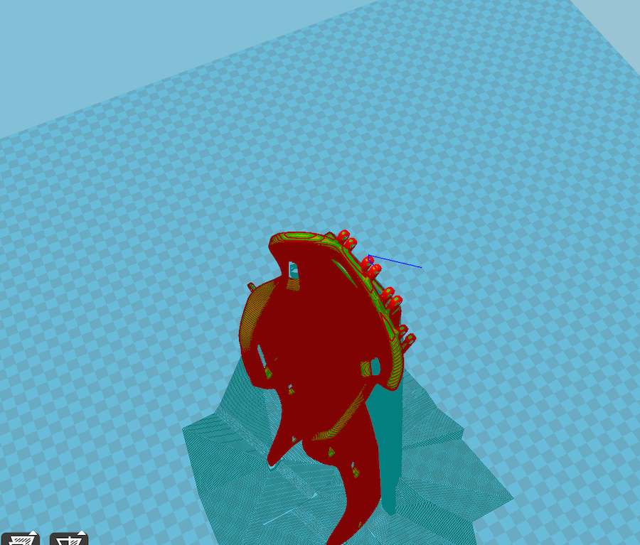
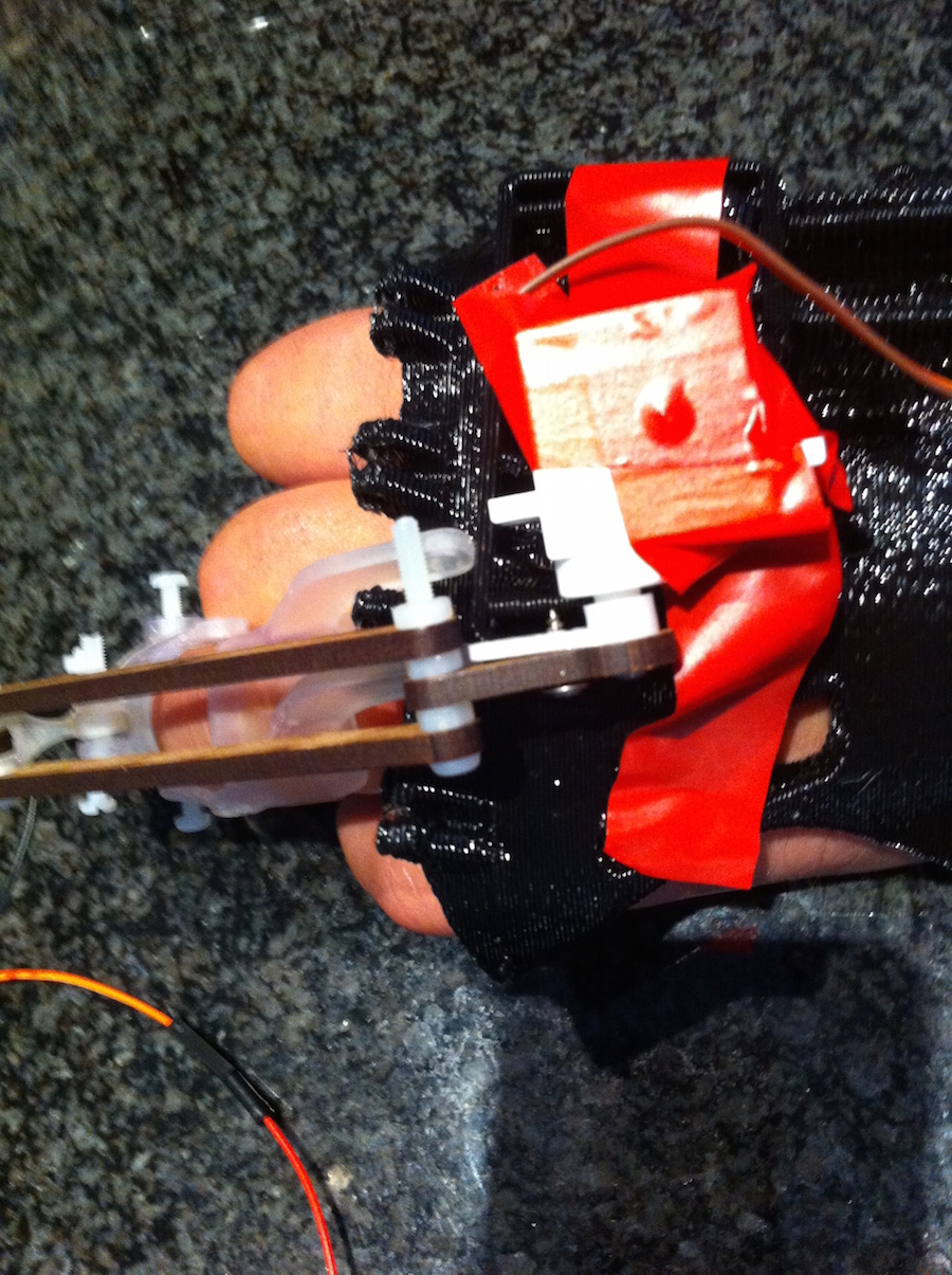
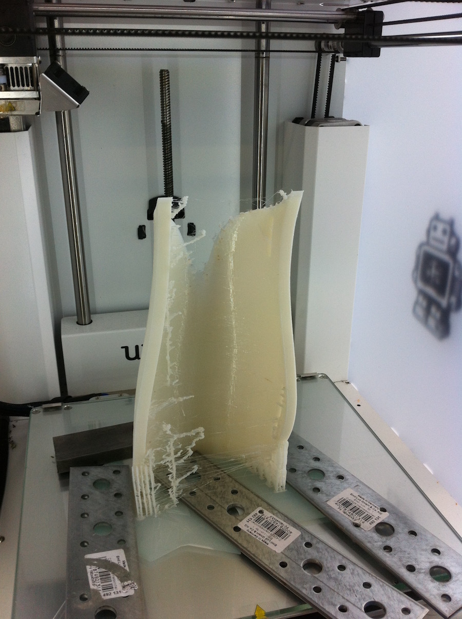
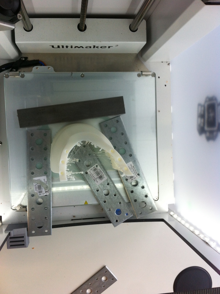
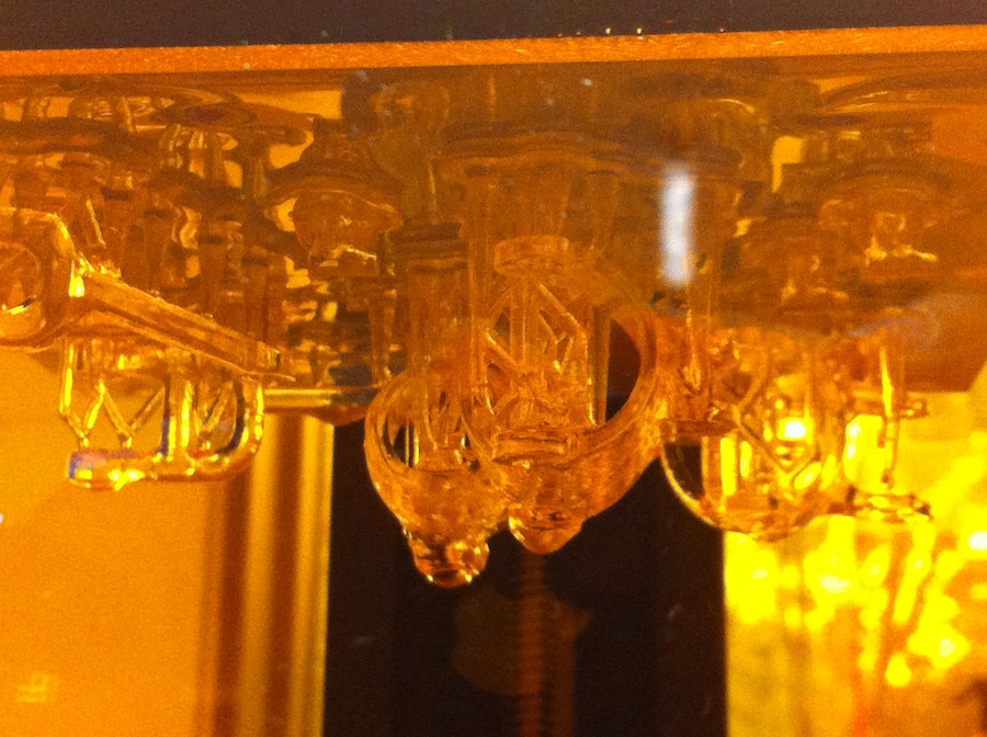
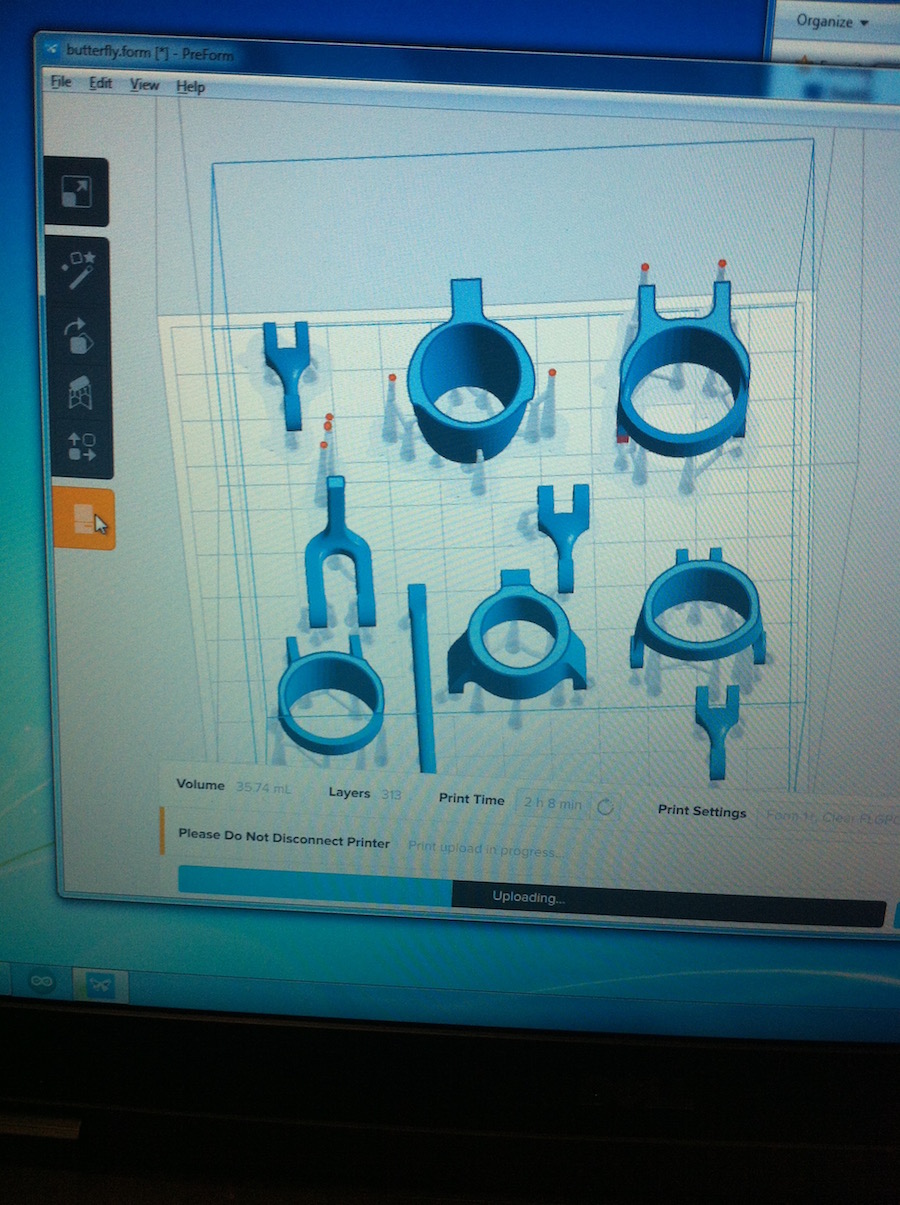
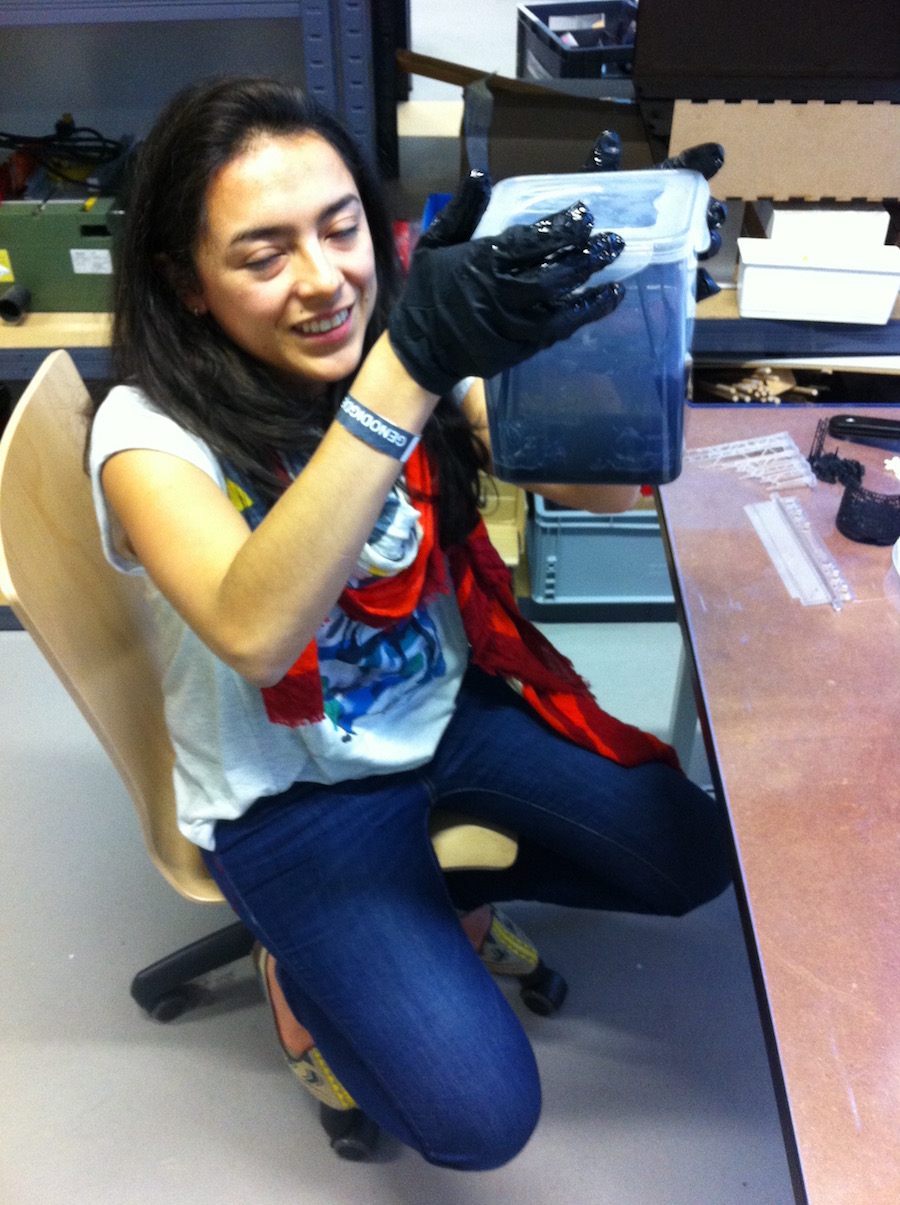
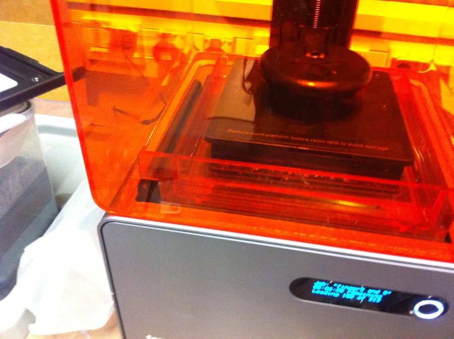
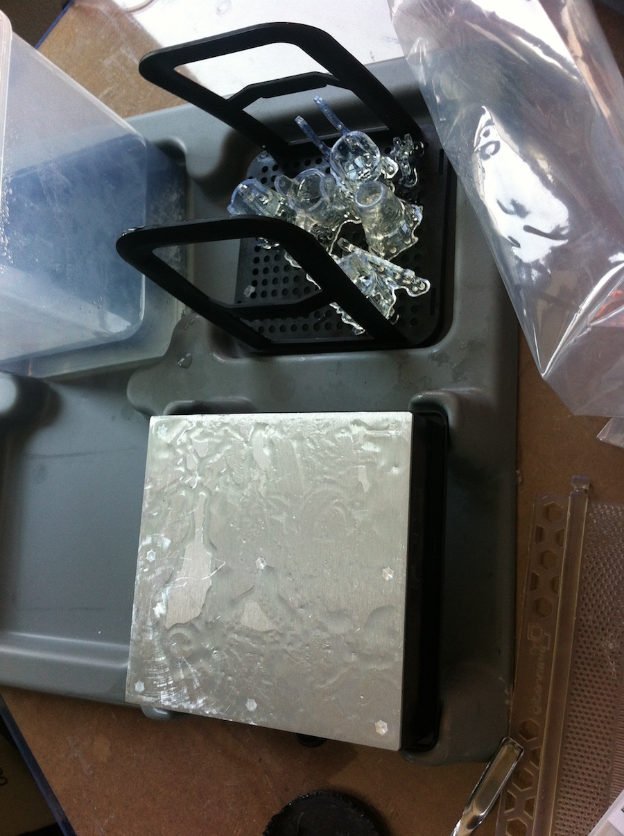
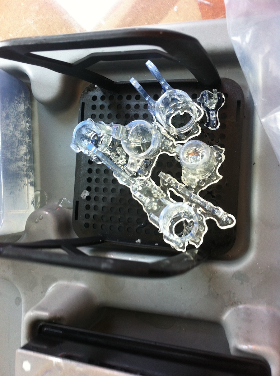
The brim doesn't stick in the bed platform: if you print with this material you have to make a big brim, and if it doesn't stick in the platform you can add some metal pieces in order to push the brim into the build plate and also to keep the heat in in the brim. You can also paste the material, but it can also be a little bit difficult to take off the platform after the print process. Fingers: The design of the fingers takes inspiration from the 3D printed rehabilitation Orthosis form ZMorph and Eliza Wrobe, thriving to understand the movement of the fingers and also the movements. The design of each finger is made in 360 Fusion with modifications to improve the use and comfortability of the phalanges design orthotic, basically in the joints assembly and the structure, which is responsible for distributing the force in the fingers. The printed parts are printed with Formlabs and with clear resin, providing a flat and fine surface that allows a smooth and comfortable contact with the skin. The design of the fingers is based on different Loft sequences. The design is parametric in order to change the values in the parametric window Modify > change parameters. In this way, you can modify the design of the fingers for orthotics in other similar cases. I based the implementation of the phalanges design in the index finger, it being the most important finger in the hand.
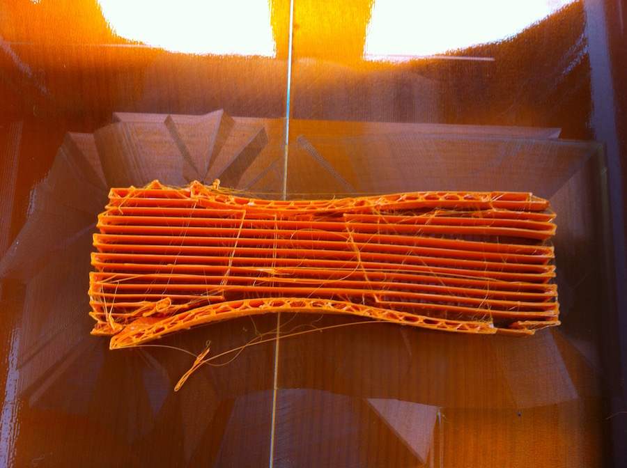
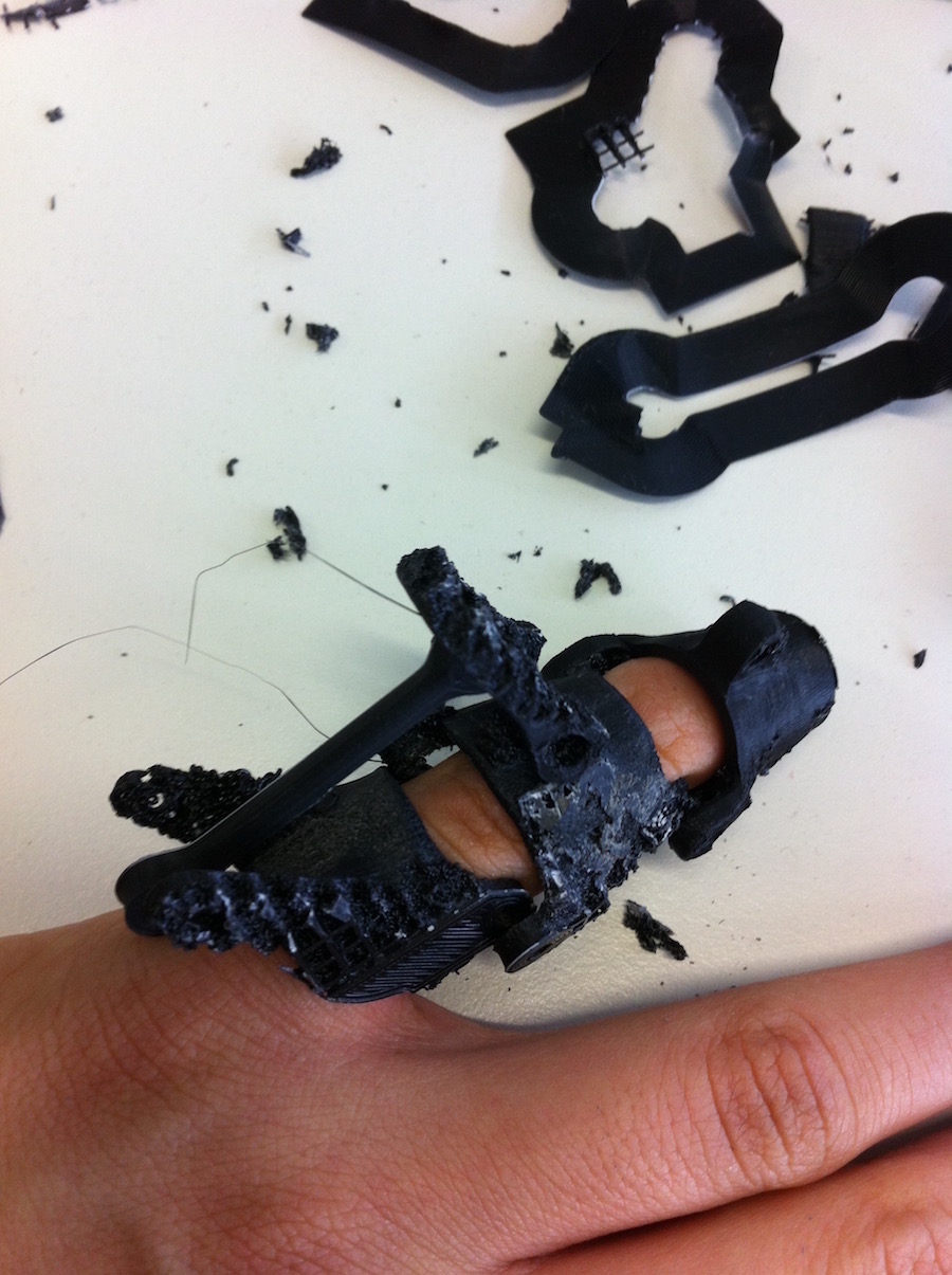
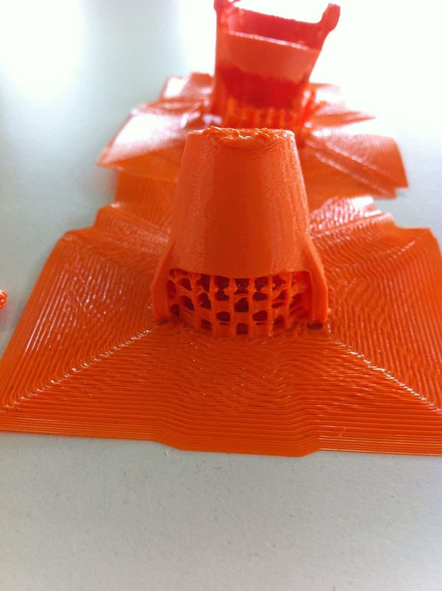
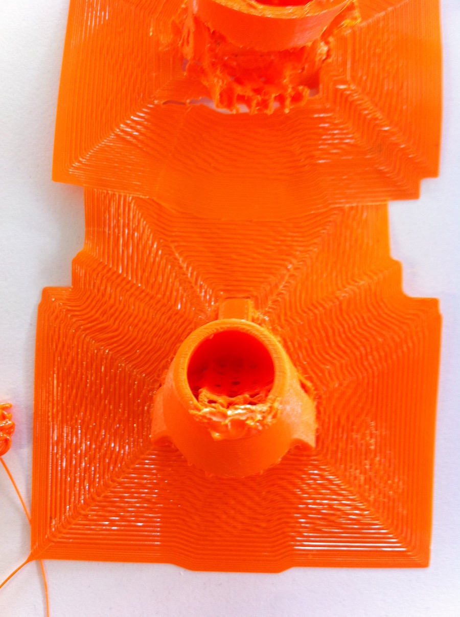
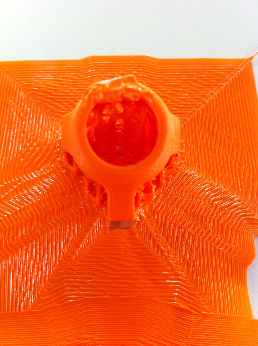
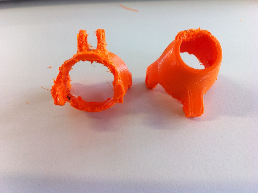
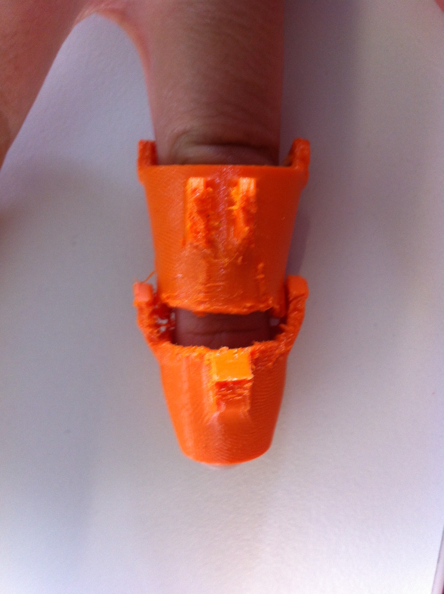
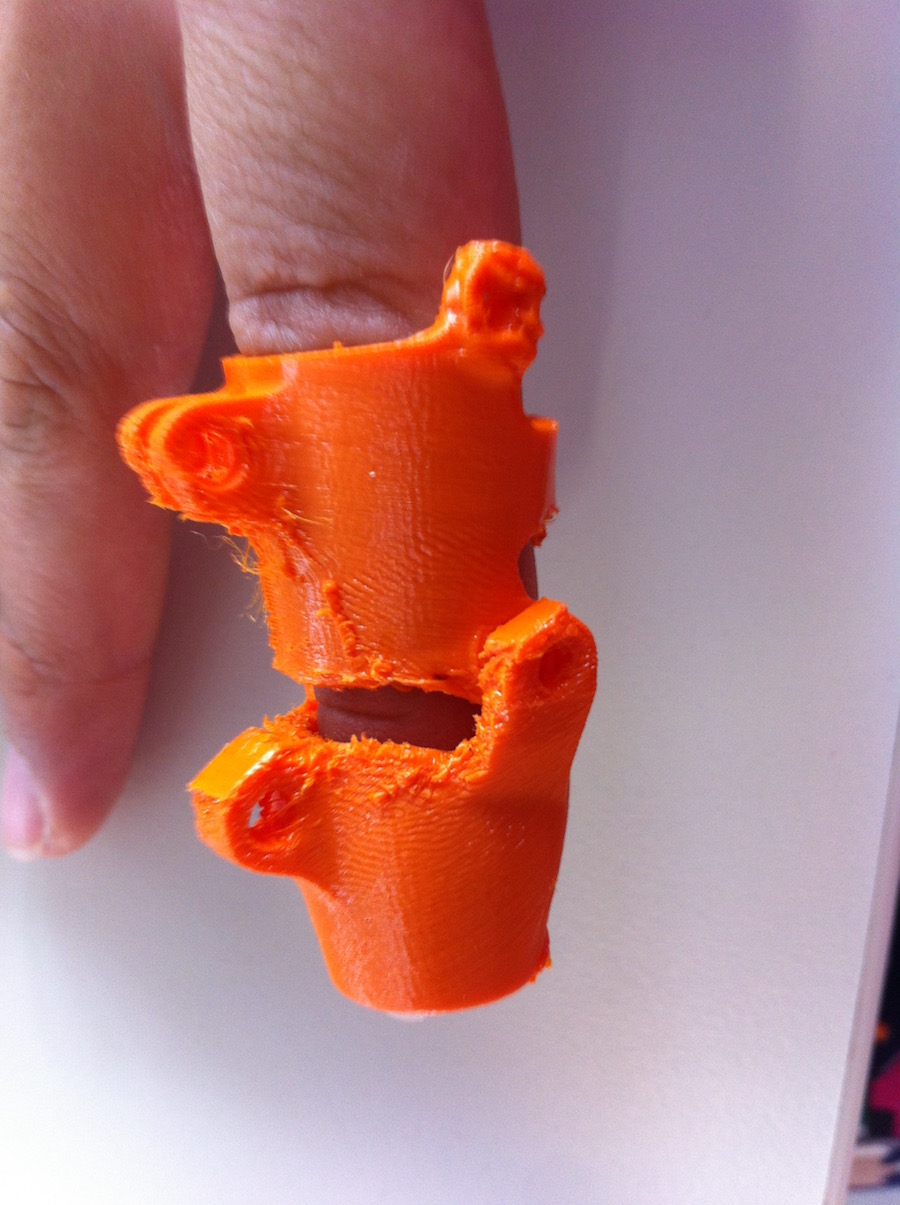
TRIALS: I tried to print the finger in one piece doing a kind of a spring making a flexible and minimizing the area of printing. 360 Fusion data: Unfortunately, reducing the area of printed material in the joint doesn’t really and making this foldable 3D Printing finger the space between the hole area too small therefore I prefered to work again with the separate phalanges and making a better joint mechanism.
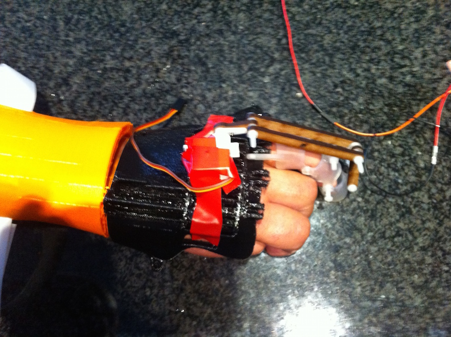
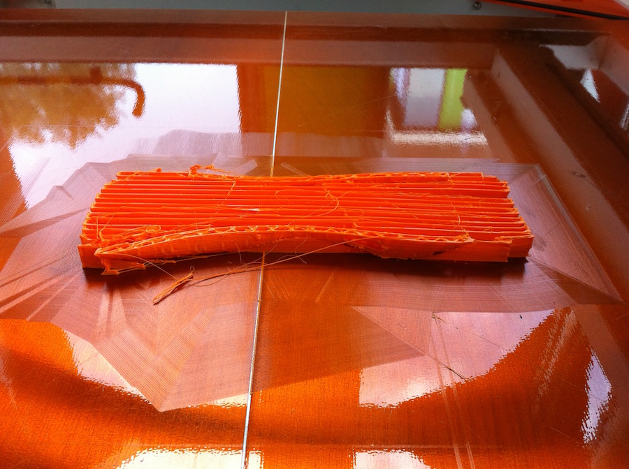
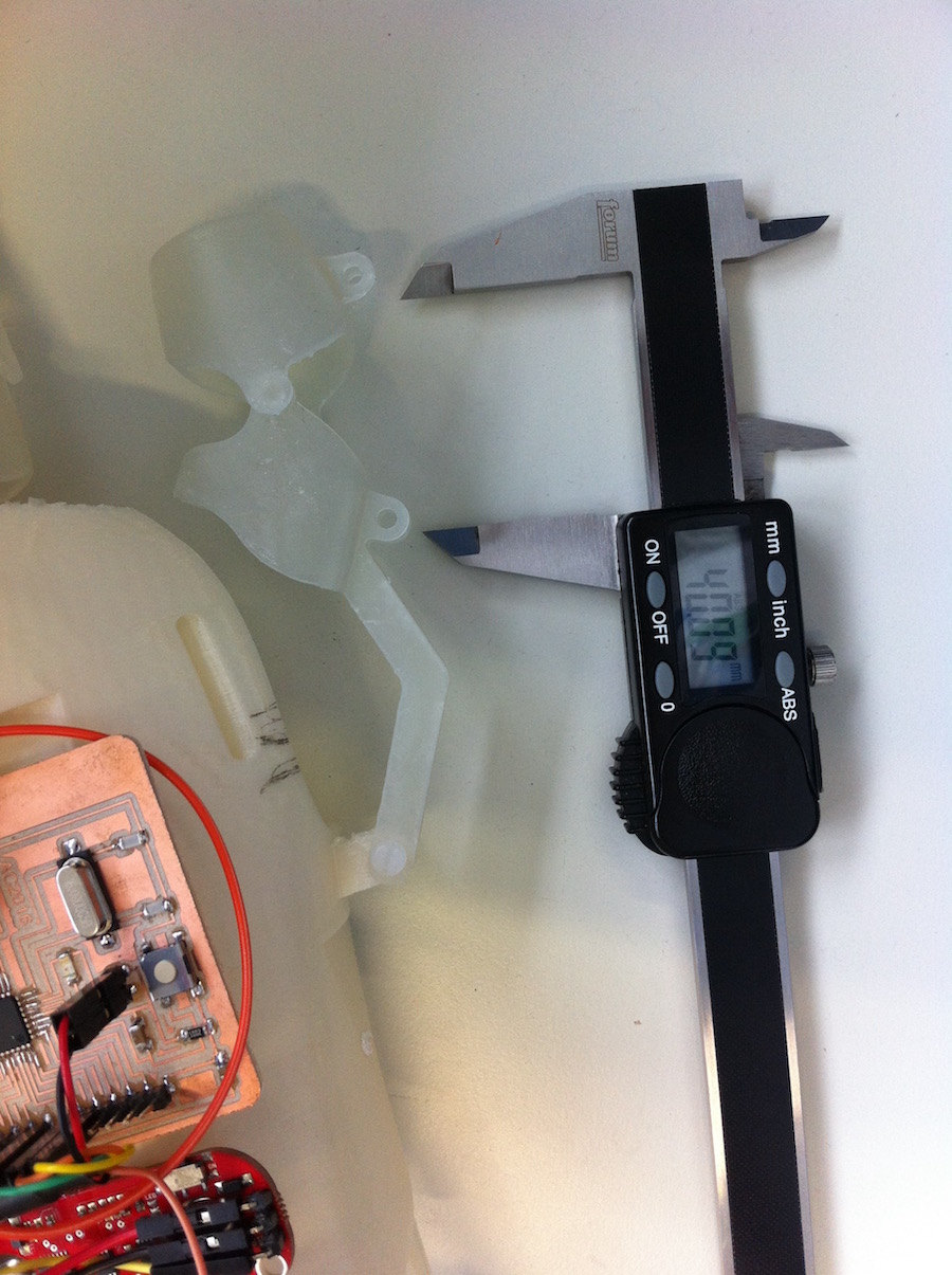
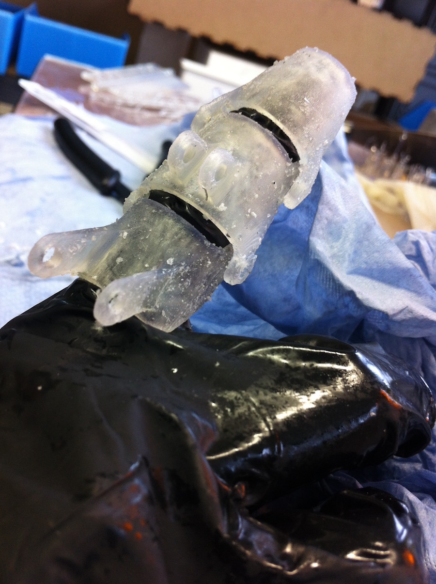
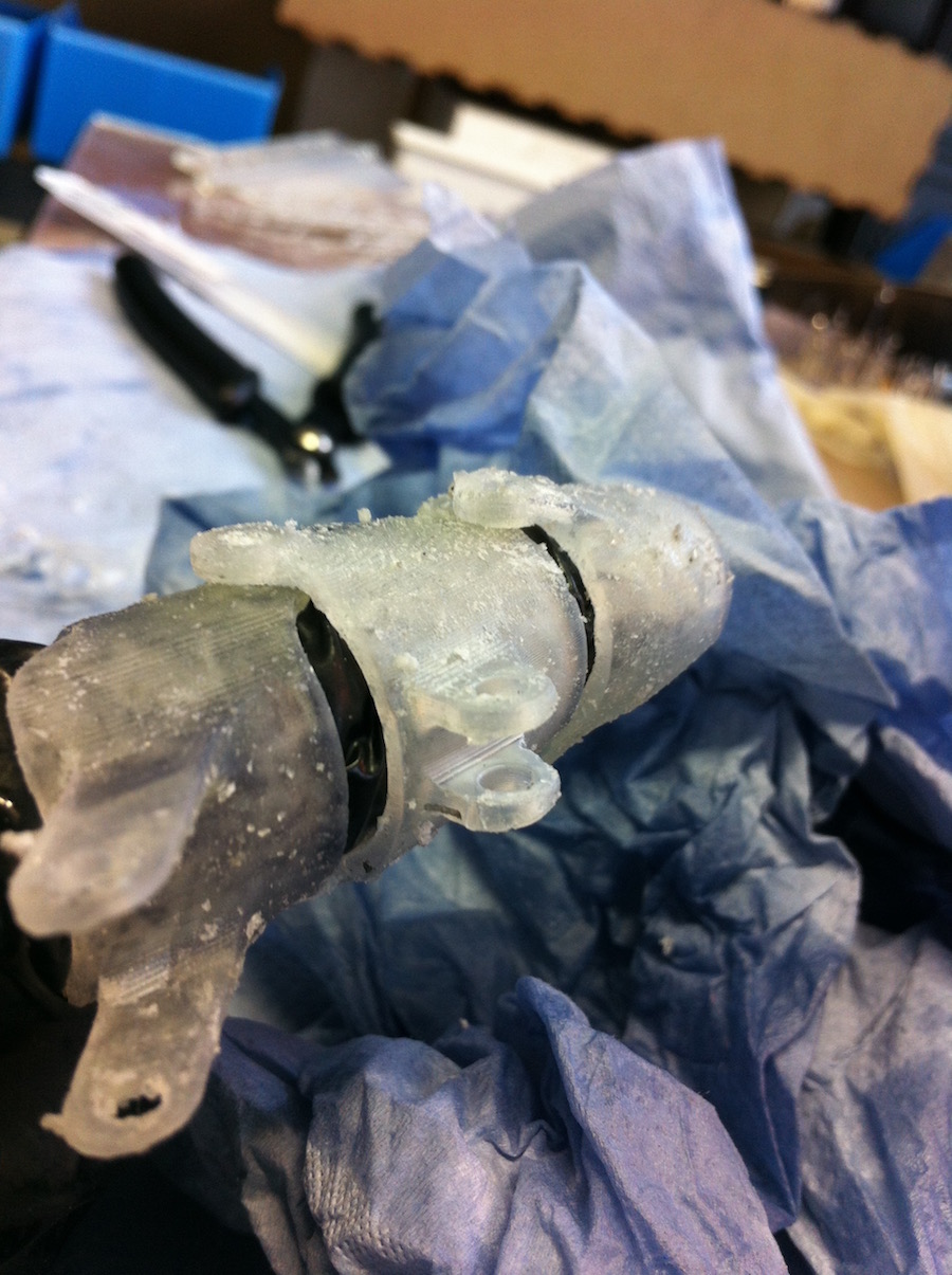
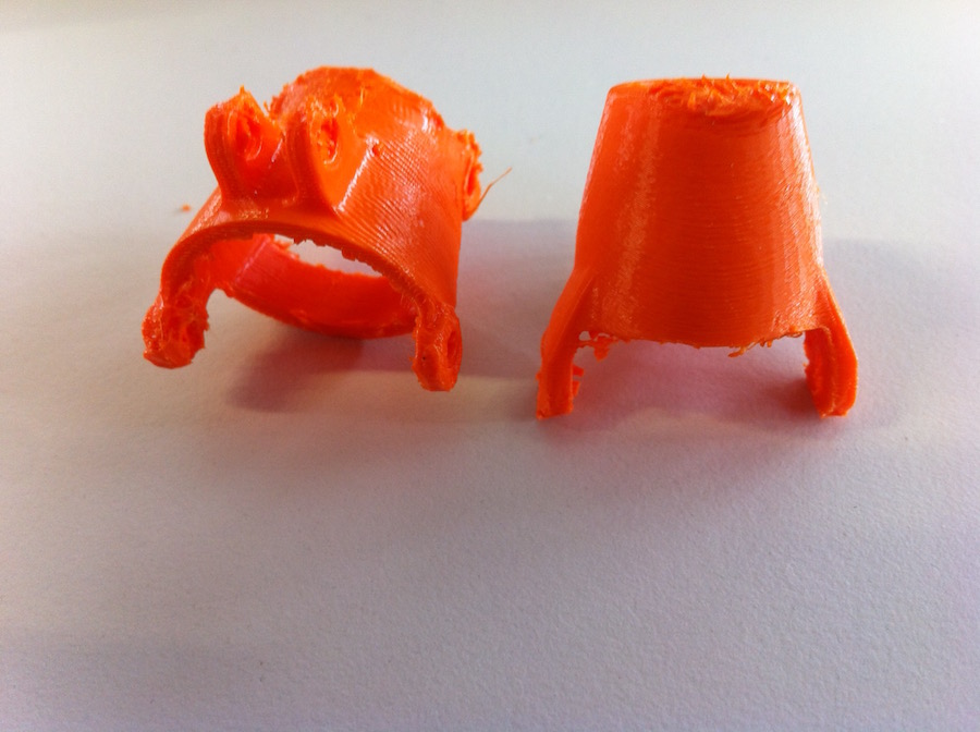
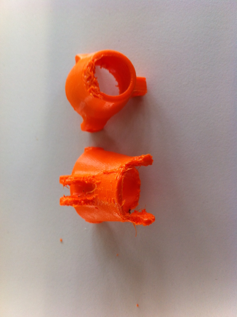
The impression, with the flexible material Innoflex 45 % orange was successful. Nevertheless the interior part came out a little bit rough, which means that I have to manipulate it after the printing process or use another printer with more precision put with flexible material. I tried to do the scanner and take measurements of the fingers. For construction, it works really well. The joint mechanism permits to print the pieces and join the phalanges, having the whole movement of 90 degrees, as you can see in the model. Troubleshooting and future work: I did several experiments making measurements of each finger. I tried to scan each finger too, but I still wasn’t able to find the right adjustments for Franks fingers, it means that I probably have to implement another method of using molding and casting to achieve the perfect size of his hand.
.
Design a 3D mold, machine it, and cast parts from it
model and patter of the 3D Scann
.
Design a 3D mold, machine it, and cast parts from it
Design a 3D mold, machine it, and cast parts from it
.
Design a 3D mold, machine it, and cast parts from it
.
.
.
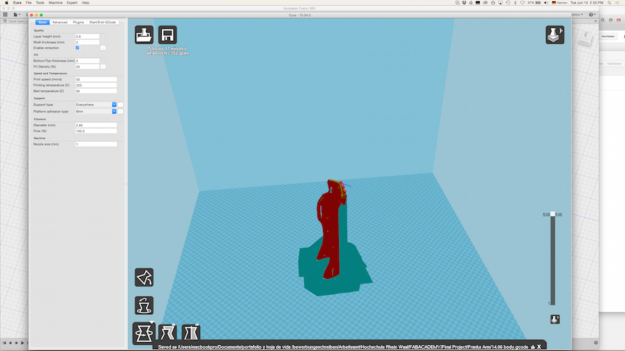
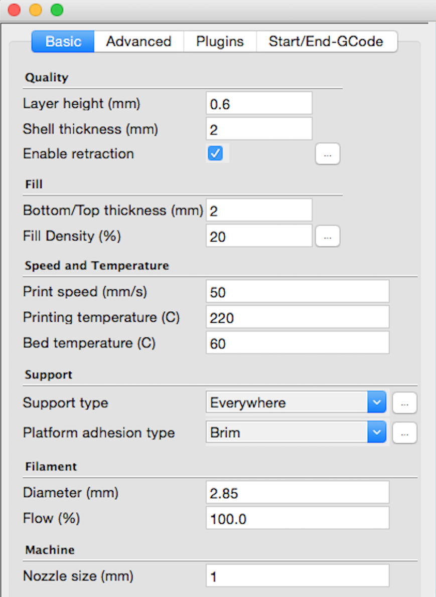
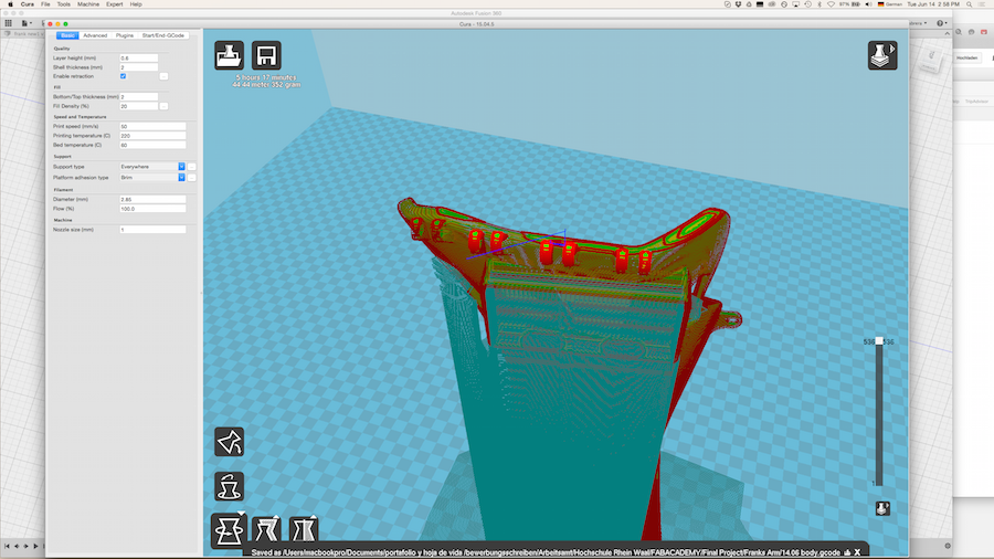
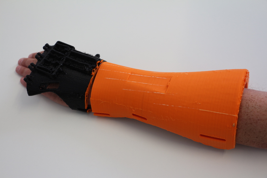
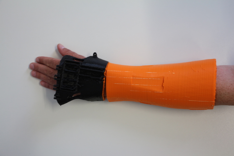
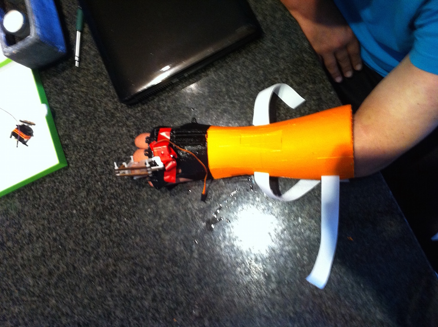
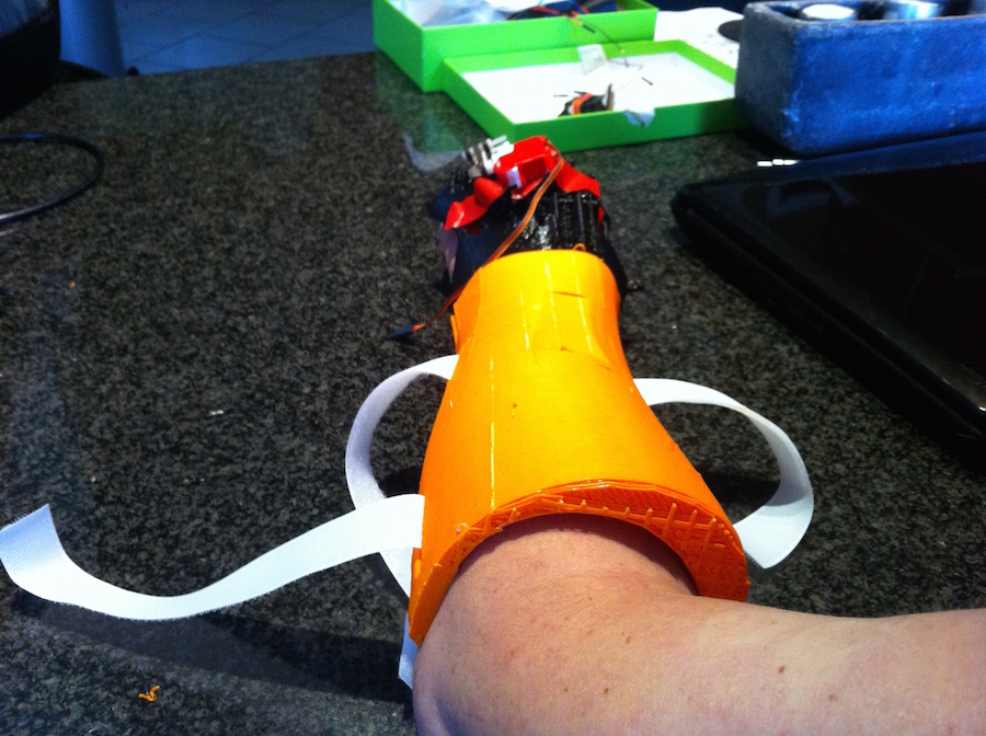
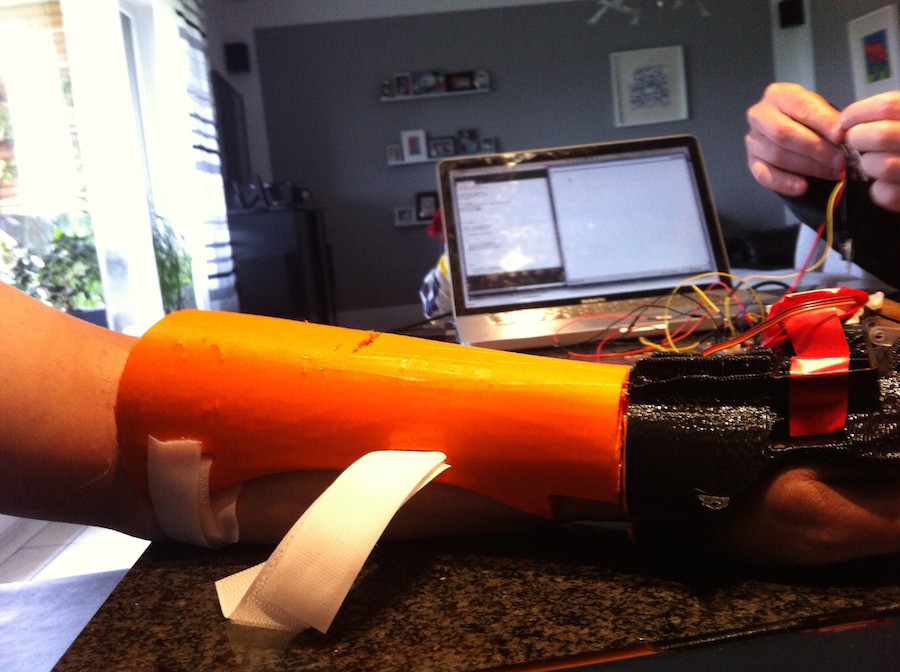
TRIALS: 1 No problems! Ultimaker : PLA Innofilm pearl white speed : 70 % Nozzle Temp: 220ºC Bed Temperature: 60 ºC Brim : 100 As you can see in the pictures you have to incinate a little bit the for in order to use the whole area of the printer. 3D Printed Splint of the external part of the forearm.
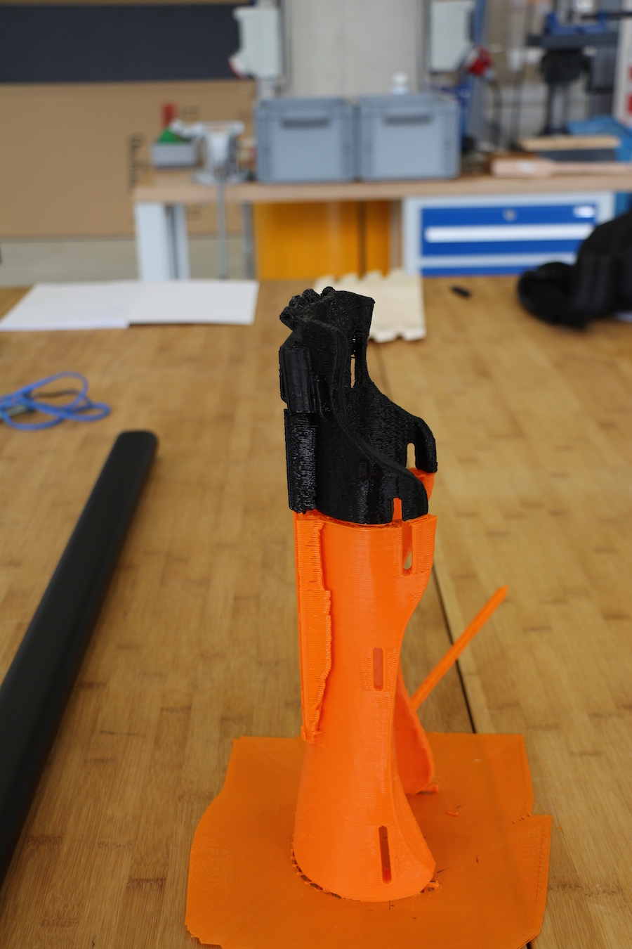
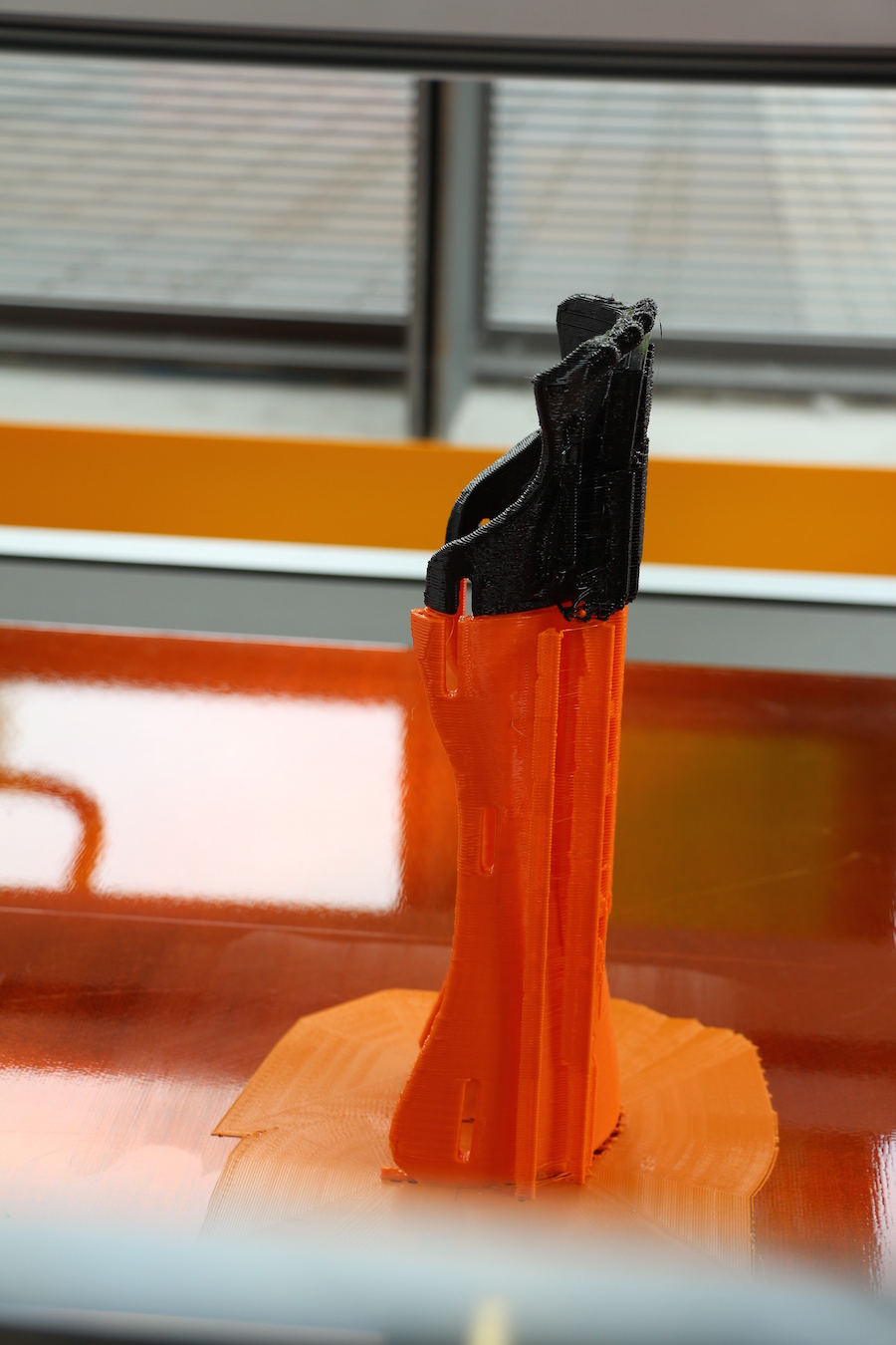
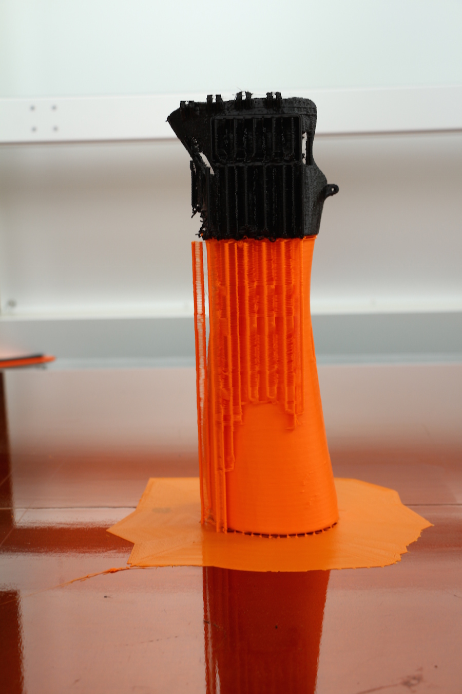
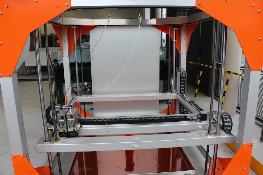
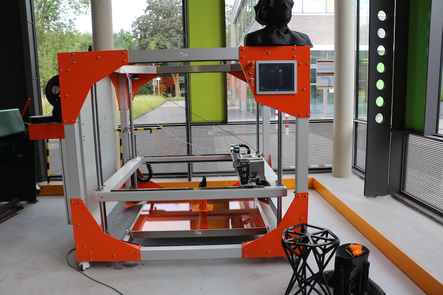
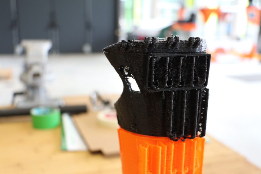
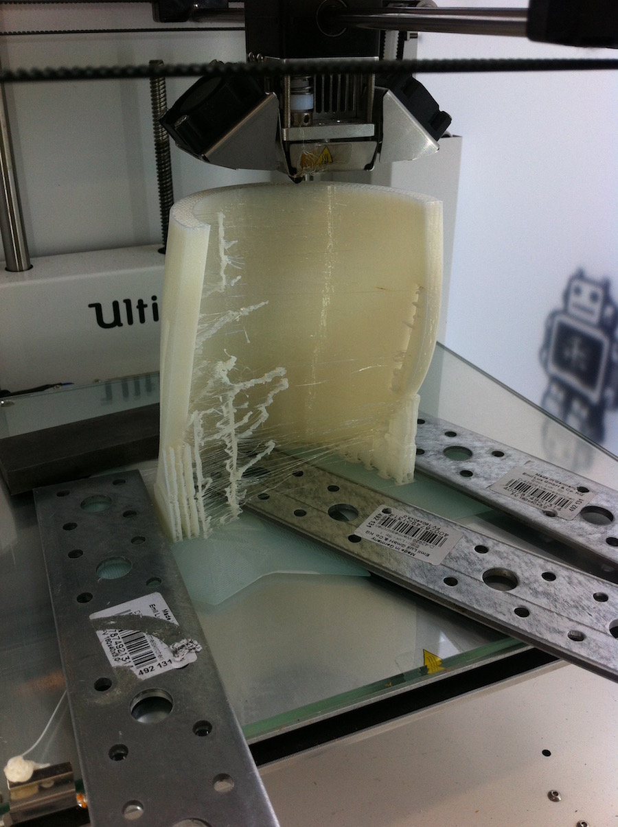
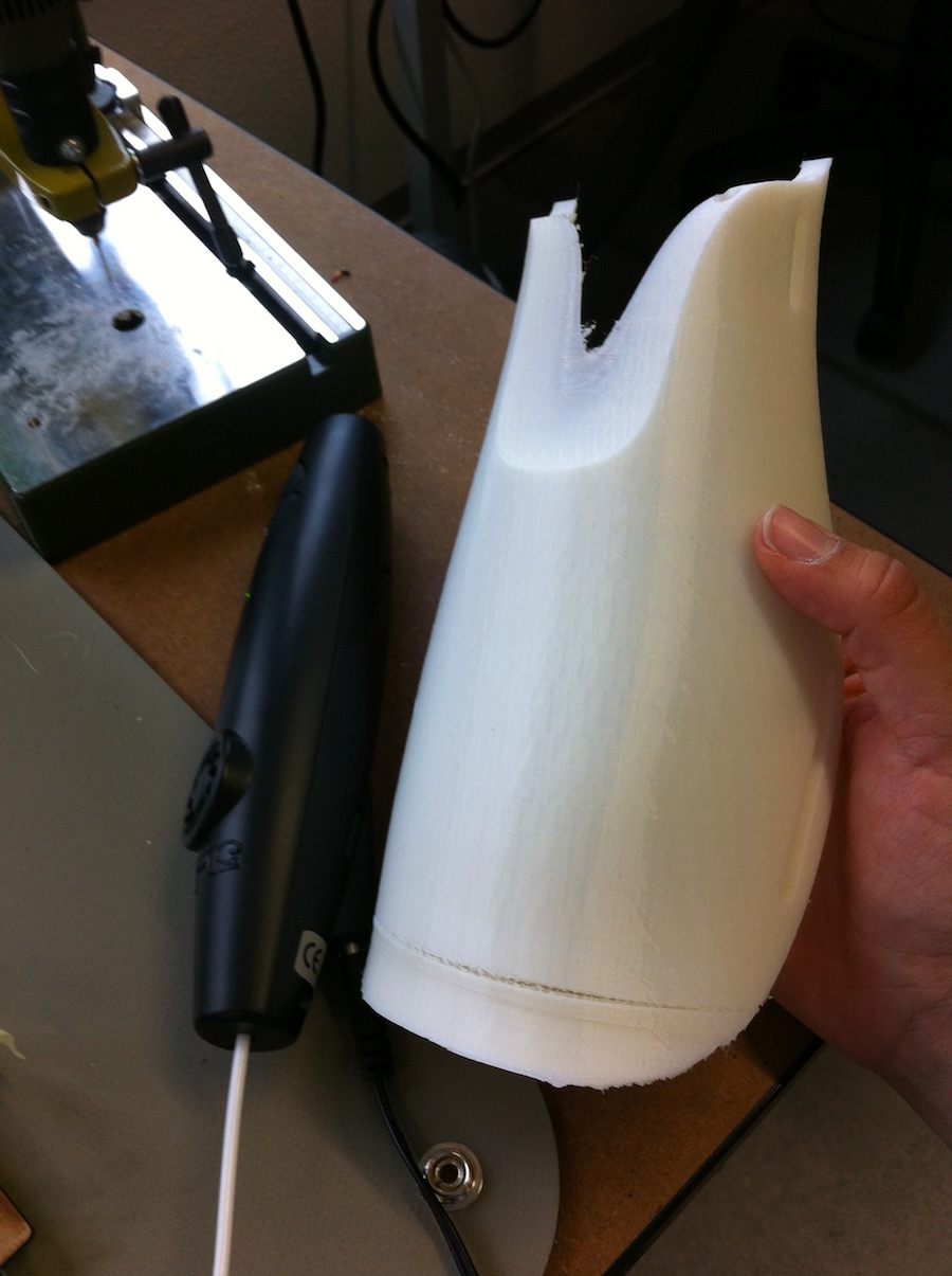
TRIALS: I tried to print the splint in one piece. The splint for Frank measures 30 mm, therefore I used the Big Rep 3D printer which has the volume to print a 1000 cubic mm Volume to 3D Printing. Nevertheless, the results are not really well done. In flexible materials the printer has a difference of the printing nozzle, Printing in vertical for. In a horizontal direction the printer stops suddenly, and the finishing with the holes for the Velcro band were in a rough form it mean that I could use for a wearable application. Usability and design consideration: I modeled the splint in two parts; one with a flexible material and the other with a rigid material. In the modelling you have to consider the attachment of both parts. I cut the splint in an organic shape in order to modify and make a harmonic and stable union of both parts. 3D Printed splint of the rigid part, backside of the hand. 3D Printing Setting sin cura :
.
.
.
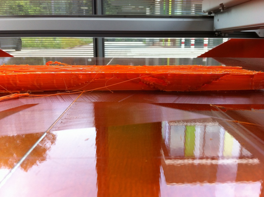
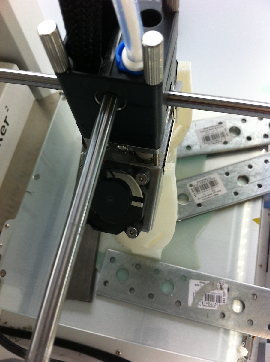
TRIALS: 10 Ultimaker: Innoflex 45% natural white Speed: 20 % Nozzle Temp: 220ºC Bed Temperature: 90ºC Brim: 100 IMPORTANT: Deactivate the retraction in Cura settings! The material is extremely difficult to print. The first time I tried to print with FABRIAL which is a hypoallergenic material. Nevertheless it didn't work and I also didn’t find very much information about the troubleshooting with the material. Problems: The filament creates a Jam in the extruder mechanism: because the Ultimaker extruder is in the back part of the printer, the carrying of the material until the nozzle, you can put oil and before printing make sure that the printer has a clean nozzle otherwise, you have to clean the nozzle various times with the Atomic Method, in order to optimize the flow of the material.
.

.
.
.
.
.
.
.
.
.
.
.
.
.
.
.
.
.
.
.
.
.
.
.
.
.