Final Project - Mechanics
3D Parametric Design
The starting point have been the design of several frames with same external shape and with press-fit joints similar to that I designed furing the week of mechanical design.
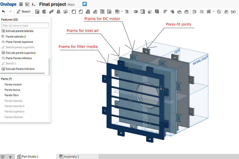
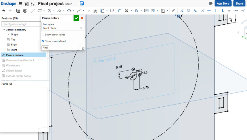
I looked at the data sheet of the DC motor that I had in order to match the motor frame of my model with the holes of the motor.
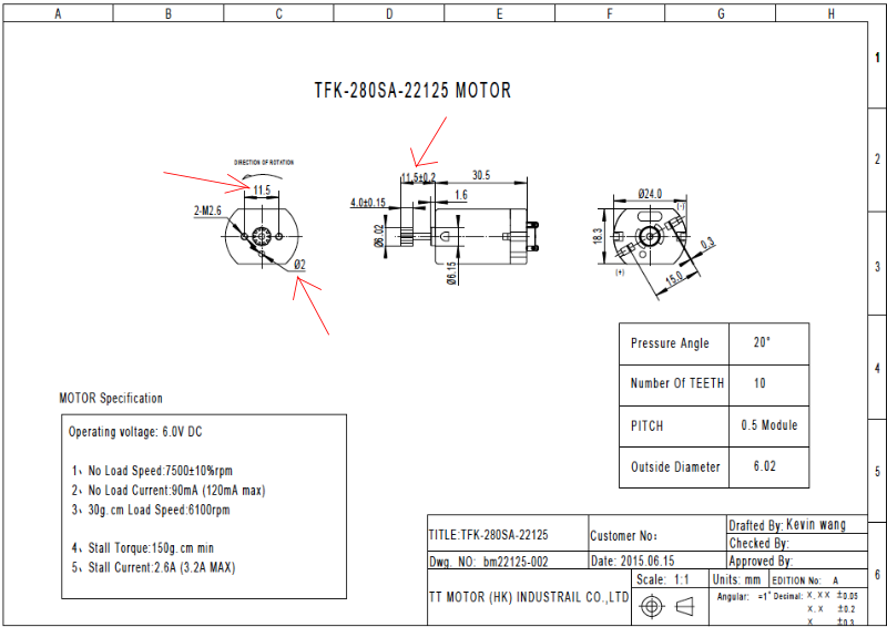
I drew the holes of the DC motor in the 3D model
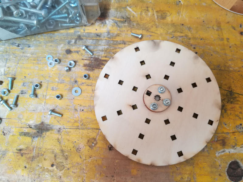
I drew the impeller with square holes to fix it to the hub of the motor and to fix the blades.
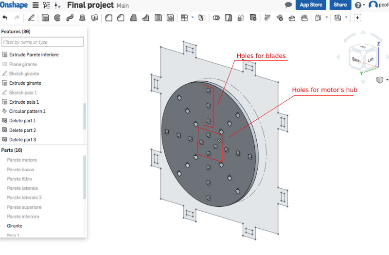
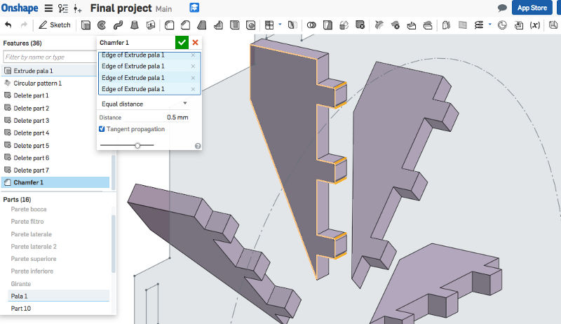
I drew the blades with a chamfer in the teeth to allow a better fixation.
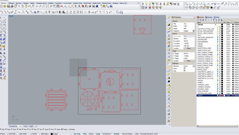
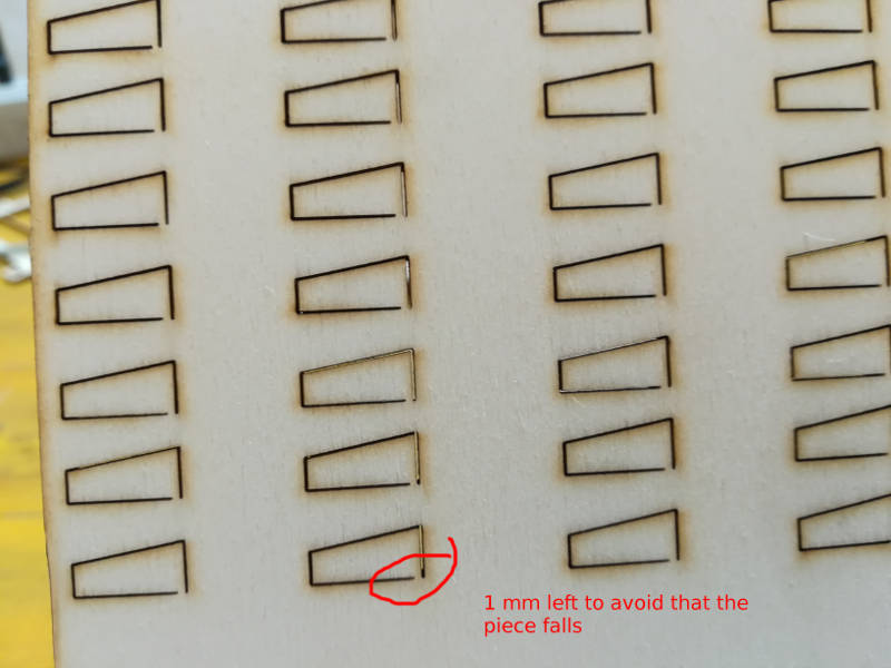
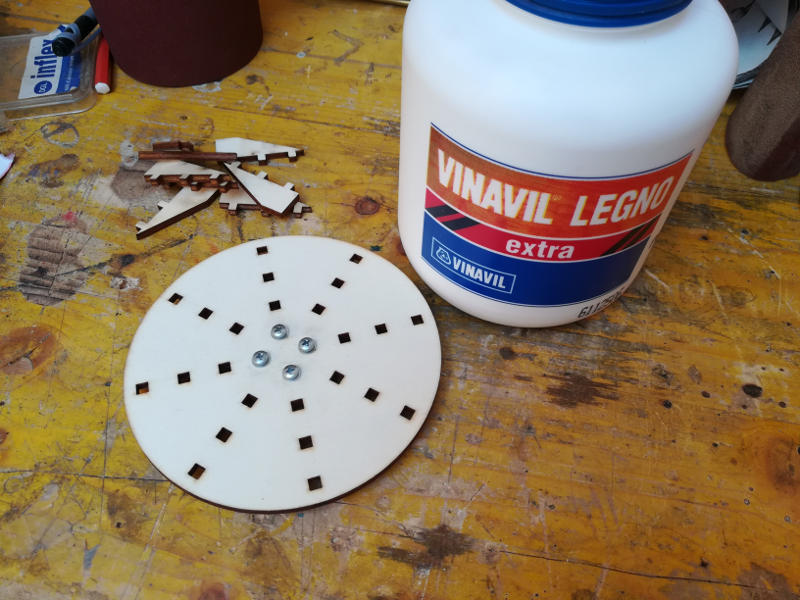
Laser cutting - Frames, walls and impeller
For this part I followed the settings I described in the Exercise 03.
Just to refresh my memory: every line needs specific layer and color.
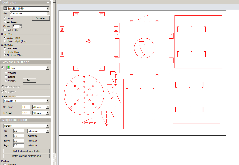
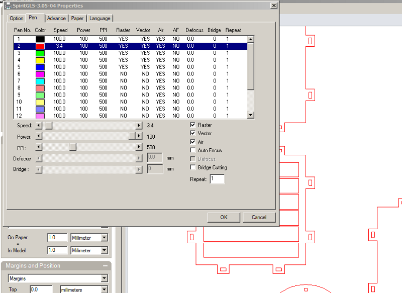
Clicking simply on print and then on Propreties I set for 4 mm of playwood the speed at 3,4 and power at 100%.
Finally I clicked on Set.. to place the view according to the position of the pieces on the file and according to the position of the wooden sheet in the laser machine.
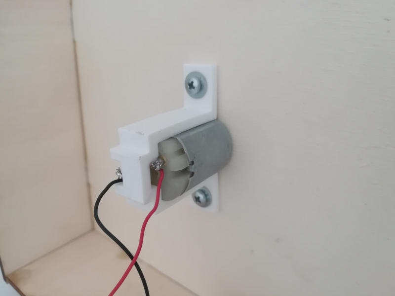
3D printing with DELTA - Support for DC motor
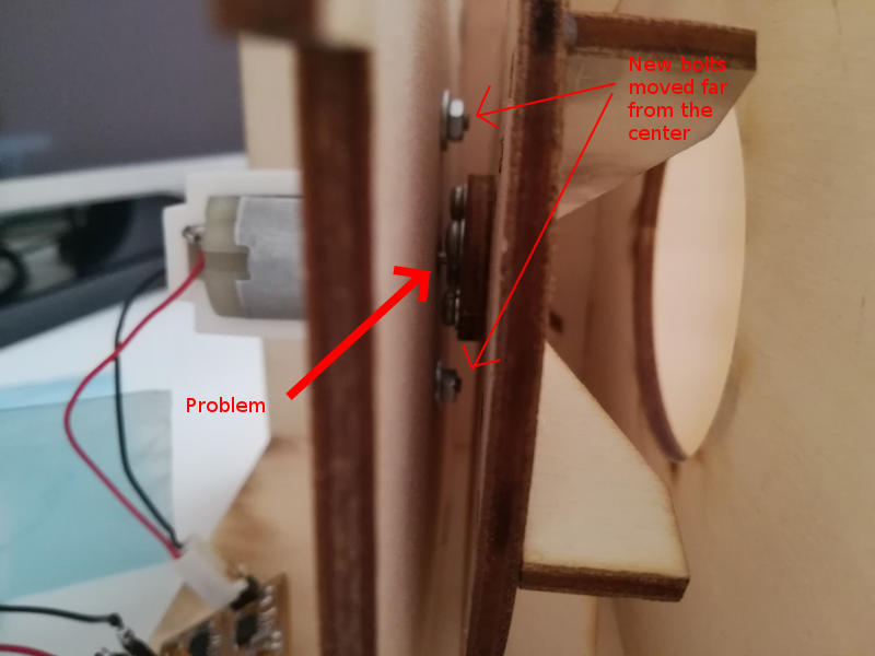
I needed a new support for the DC motor because I had a mechanical interfernece between the screws that were fixing together the impeller and the screws that should fix the motor to the frame. So I had to fix the motor with some screws placed farer from the center point. To do this job I thought to design a support with OnShape and to make it with an additive processing like 3D printing.

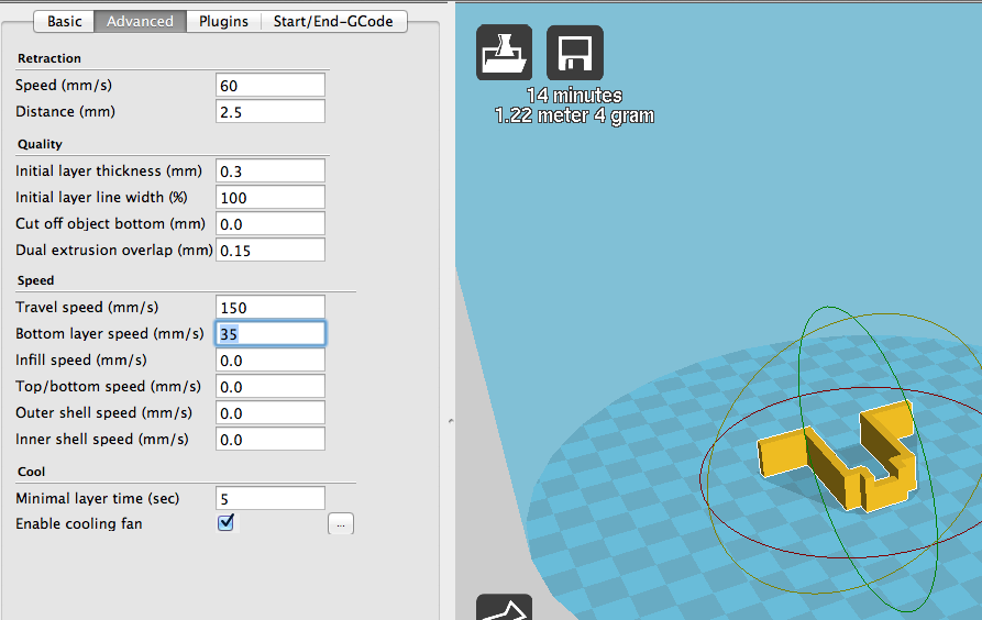
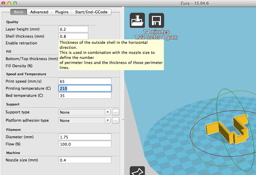
This time I used a new 3D printing machine: the Delta 2040.
Here below I saved in the pictures the settings that worked fine for my object.

I drilled two holes, I put two M3 bolts and this was the result.
Assembly
Impeller


External box
